CAT Bucyrus 6030 Hydraulic Shovel Operation & Maintenance Manual EM030151-0 – PDF DOWNLOAD
$29.95
CAT Bucyrus 6030 Hydraulic Shovel Operation & Maintenance Manual EM030151-0 – PDF DOWNLOAD
J8F00101- Up
J7F00401- Up
Description
CAT Bucyrus 6030 Hydraulic Shovel Operation & Maintenance Manual EM030151-0 – PDF DOWNLOAD
FILE DETAILS:
CAT Bucyrus 6030 Hydraulic Shovel Operation & Maintenance Manual EM030151-0 – PDF DOWNLOAD
Language : English
Pages : 428
Downloadable : Yes
File Type : PDF
DESCRIPTION:
CAT Bucyrus 6030 Hydraulic Shovel Operation & Maintenance Manual EM030151-0 – PDF DOWNLOAD
J8F00101- Up
J7F00401- Up
INTRODUCTION:
PREFACE:
- These operating instructions are designed to fa- miliarize the operator with the machine
and its designated use. - The operating instructions contain important in- formation on how to operate the machine
safely, properly and with maximum efficiency. Observing these instructions helps to
prevent hazardous situations, to reduce repair costs and downtimes and to increase the
reliability and service life of the machine. - The operating instructions must be supplemented by the respective national rules and regulations
for accident prevention and environmental protection. - The operating instructions must always be avail- able in the driver’s cab of the machine.
- The operating instructions must be read and put into practice by any person in charge
of carrying out work with or on the machine, such as
■ operation, including setting-up, troubleshoot- ing in the course of work, care,
evacuation of production waste and disposal of fuels and consumables,
■ maintenance (inspection, servicing, repair) and / or
■ transport.
In addition to the operating instructions and the mandatory rules and regulations for
accident pre- vention and environmental protection in the user’s country and at the place where the
machine is to be used, the generally recognized technical rules for safe and proper working must
be observed .
- The operating instructions are directed to the con- struction-machine specialist. They cannot
provide basic know-how. This can be acquired, for exam- ple, in several days’ instruction by
a qualified GERMANY Germany mechanic or by attending an Terex-Germany training course for
operators or maintenance personnel.
- The Operation and Maintenance Manual are di- rected to the mining-machine specialist. They can- not provide basic know-how. This can be acquired, for example, in several days’ instruction by a qualified CGM-HMS GmbH mechanic or by attending an CGM-HMS GmbH training course for operators or maintenance personnel.
- The CGM-HMS GmbH after-sales service will be pleased to deal with any queries you may have after reading through the Operation and Maintenance Manual.
CGM-HMS GmbH = - Caterpillar Global Mining Hydraulic mining Shovels GmbH.
- Operation and Maintenance Manuals does not contain work instructions for carrying out major repairs. Such work is willingly done for you by your Caterpillar dealer.
IMAGES PREVIEW OF THE MANUAL:
TABLE OF CONTENTS:
CAT Bucyrus 6030 Hydraulic Shovel Operation & Maintenance Manual EM030151-0 – PDF DOWNLOAD
1 INTRODUCTION 1-1
ALL PRODUCTS FOREWORD 1-3
Literature Information 1-3
Safety 1-3
Operation 1-3
Maintenance 1-3
Certified Engine Maintenance 1-3
Machine Capacity 1-4
Product Identification Number 1-4
California Proposition 65 Warning 1-4
PREFACE 1-5
Further machine documentation 1-5
WARRANTY 1-6
FUNDAMENTAL SAFETY INSTRUCTIONS 1-7
Warnings and symbols 1-7
Declaration of Conformity 1-7
Visibility Information 1-8
Noise Emission Information 1-8
Vibration Information 1-8
Sound Level Information for Machines in Eurasian Economic Union Countries 1-8
Restricted Visibility 1-9
DESIGNATED USE, UNAUTHORIZED USE 1-10
Specified Useful Life or Expected Life 1-10
ORGANIZATIONAL MEASURES 1-11
Selection and qualification of personnel; basic responsibilities 1-12
Safety instructions governing specific operational phases 1-12
Special work in conjunction with utilization of the machine and maintenance and repairs as well as
troubleshooting during work; disposal of parts and consumables 1-13
Warning of special dangers 1-14
Gas, dust, steam and smoke 1-14
Hydraulic equipment 1-15
FIRE AND EXPLOSION HAZARD 1-16
NOTES 1-17
2 OPERATION 2-1
OPERATION – SAFETY INSTRUCTIONS 2-3
Visibility aids 2-4
Operation and Maintenance Manual, where to store it in the operator’s cab 2-4
FIRE AND EXPLOSION HAZARD 2-5
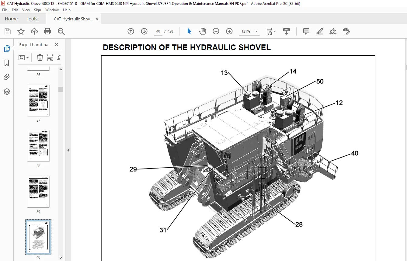
DESCRIPTION OF THE HYDRAULIC SHOVEL 2-6
Hydraulic shovel layout – upper structure 2-7
Hydraulic shovel layout – undercarriage and attachment 2-9
EM030151-0
Undercarriage 2-10
Upper structure 2-10
Drive unit 2-10
Hydraulic system 2-10
Control and Monitoring Platform (CAMP) 2-10
Board-Control-System (BCS) 2-11
Demand control / Zero-flow regulation 2-11
Automatic reset to idling 2-11
Electrical system 2-11
Safety films and warning messages 2-12
ANSI – compliant safety messages set 2-13
Safety messages (ANSI) – Description 2-19
Additional messages (ANSI) – Description 2-25
Product Identification Number (18) 2-30
CE-Plate, European Union (11) 2-30
Eurasian Economic Union 2-32
Fire Extinguisher Location (If equipped) 2-32
Mounting and Dismounting the machine – Safety instructions 2-33
Access ladder – Lighting 2-33
Access ladder – Function 2-34
Emergency exit in operator’s cab and escape ladder 2-35
Cab interior lighting – Switch on and off 2-36
Maintenance lights – Switch on and off 2-37
Emergency shut-off – Function 2-38
Putting the machine back into operation – Reset of emergency shut off function 2-39
Battery isolator switch – Shut off supply voltage 2-40
Starter isolator switch – Shut off starter voltage 2-40
Operator’s seat 2-41
Reducing operator’s exposure to vibrations 2-43
Trainer’s / instructor’s seat 2-43
Windscreen washer – Fill 2-43
MONITORING, WARNING AND CONTROL ELEMENTS 2-44
Engine 1 (LH), control and monitoring 2-51
Engine 2 (RH), control and monitoring 2-53
PUTTING THE MACHINE INTO OPERATION 2-66
Electrical Storm Injury Prevention 2-66
Reducing the operator’s exposure to noise 2-66
Refuelling 2-67
Diesel fuel – recommendations 2-67
Fuel Additives 2-68
Biodiesel 2-68
Coolant Information 2-68
Service Station (fast fill arm) – Function 2-69
Emergency off switch 2-70
Back-up heating (if equipped) – Fill fuel 2-75
Electrical system – Switch on and off 2-75
Engines – Emergency shut-off 2-75
Preheating system for engine and hydraulic oil (if equipped) 2-76
Level indicator in operator’s cab – Function 2-77
Hydrocarbon Mitigation (TIER4 engines only) 2-77
EM030151-0
STARTING AND STOPPING THE ENGINES 2-78
Engines – Start 2-78
Starting the left-hand engine 2-78
Starting the right-hand engine 2-78
Engines – Adjust speed 2-79
Engines – Start at low temperatures 2-79
Engines – Shutdown 2-80
Engines – Idle Shutdown 2-80
Engines – Hard Shutdown 2-80
Shutdown the left-hand engine 2-80
Shutdown the right-hand engine 2-80
AIR CONDITIONER (IF EQUIPPED) 2-81
Back-up heating operator’s cab (if equipped) 2-82
Back-up heating (if equipped) 2-83
OPERATIONAL PRACTICES 2-84
Working operation – Safety instructions 2-84
Before starting work 2-85
Machine Operating Temperature Range 2-85
Warming up the hydraulic system 2-85
Running-in instructions for hydraulic cylinders 2-86
Electronic hydraulic shovel control (pilot control) – activate 2-86
Working operation – basics 2-87
OPERATION TECHNIQUES 2-93
Machine operation with backhoe attachment, Best Practices 93
Backhoe Operation – Restricted Operation 2-103
Machine operation with face shovel attachment – Best Practices 2-114
Face Shovel Operation – Restricted Operation 2-128
TRAVELING 2-143
Traveling – Safety Instructions 2-143
Before starting traveling 2-144
Traveling – Basic Movements 2-146
Counter-rotation turns / Turning on the spot 2-149
Track Parking Brake – set/release 2-150
Traveling speed – adjust 2-150
Traveling uphill and downhill on ramps and steep slopes 2-151
Traveling over long distances 2-153
Traveling – Best Practices 2-155
Traveling – Restricted Operation 2-156
Maximum Machine Inclinations 2-159
TRANSPORTING THE MACHINE 2-160
Transport – Safety instructions 2-160
Engine-off lowering of the attachment 2-161
After daily operation 2-162
ASSEMBLING ATTACHMENT – SAFETY INSTRUCTIONS 2-163
Securing the machine 2-164
Corrosion protection for pins and bearings (bushings and hubs) 2-165
EM030151-0
MONITORING CAMERAS – FUNCTION 2-166
ENTERTAINMENT RADIO (IF EQUIPPED) – OPERATE 2-167
Entertainment Radio – Panel Controls 2-168
Entertainment Radio – General Operation 2-169
USB/MP3 Playback 2-170
Tuner Operation 2-170
NOTES 2-174
3 INSPECTION AND SERVICING 3-1
INSPECTION AND SERVICING – SAFETY INSTRUCTIONS 3-3
INSPECTION AND SERVICING WORK, FIRE AND EXPLOSION HAZARD 3-7
INSPECTION AND SERVICING PLANS – INSTRUCTIONS 3-9
Refer to chapter “Engine oil service interval table” for more information. 3-9
Also refer to Special Publication, SEBU6250, “Caterpillar Machine Fluids Recommendations”. This
publication is available from your Cat dealer. 3-9
C27 Engine Maintenance Interval Schedule – Notes 3-10
Plan V 3-11
Plan N 3-13
Plan T and W 3-15
Plan A – E 3-17
LUBRICATING CHART – GREASE 3-24
Lubricating chart – Grease (legend) 3-25
INSPECTION PLAN – OIL 3-26
Inspection plan – Oil (legend) 3-27
Engine oil service interval table 3-28
Engine oil service interval table (with Reserve™ Oil Tank) 3-29
LUBRICANT VISCOSITIES AND REFILL CAPACITIES 3-30
Lubricant Viscosities (Fluid Recommendations) 30
Engine Oil 31
Hydraulic Fluids 3-32
Other Fluid Applications 3-33
Diesel Fuel Recommendations 3-34
Fuel Additives 3-34
Biodiesel 3-34
S·O·S Information 3-35
Coolant Information 3-35
Refill quantities – Oil 3-37
Refill quantities – Grease 3-38
Refill quantities – Other 3-38
SERVICING WORK 3-39
Hose line for oil and cooling liquid changes 3-39
ENGINE 3-40
Engine – Safety instructions 3-40
Walk-Around Inspection 3-41
Belt – Inspect/Replace 3-42
Fuel Injector – Inspect/Adjust 3-43
EM030151-0
Engine Mounts – Inspect 3-43
Engine Oil Sample – Obtain 3-44
Engine Valve Lash – Check 3-45
Engine Valve Rotators – Inspect 3-45
Engine Hoses and Clamps – Inspect/Replace 3-46
Engine oil level – Check / Top up 3-49
Engine oil tank oil level (if equipped) – Check / Top up 3-50
Engine oil – Change 3-51
Engine oil tank (if equipped), Drain oil 3-53
Engine oil filter – Replace 3-55
Engine oil tank (if equipped) oil filters – Replace 3-55
Engine crankcase breathers – Clean 3-56
Cold-starting fluid (ether) pressure vessel – Replace 3-57
COOLING SYSTEM 3-58
Temperature 3-58
Radiators 3-59
Cooling-liquid level – Check 3-59
Cooling liquid – Change 3-62
Coolant Extender (ELC) – Add 3-65
Coolant Sample (Level 1) – Obtain 3-66
Coolant Sample (Level 2) – Obtain 3-67
Cooling System Supplemental Coolant Additive (SCA) – Test/ Add 3-68
AIR-INTAKE SYSTEM 3-70
Engine Air Filter Primary Elements – Replace 3-71
Engine Air Filter Secondary Element – Replace 3-72
Engine Air Precleaner – Clean 3-73
Air-intake lines – Inspect 3-73
FUEL SYSTEM 3-74
Fuel system – Safety instructions 3-74
Fuel filter – System 3-74
Primary fuel filter – Drain water 3-75
Primary fuel filter – Replace 3-75
Secondary / Tertiary fuel filter – Replace 3-76
Fuel tanks – Drain / Clean 3-76
Fuel System – Prime 3-78
ELECTRICAL SYSTEM 3-79
Electrical system – Safety instructions 3-79
Alternator – Instructions 3-79
Electrical circuit diagrams 3-79
Electrical system switch-cabinets 3-79
Lamps and bulbs – Replace 3-79
Battery – Clean 3-79
Charging batteries inside the machine – Safety instructions 3-80
Battery – Remove / Install 3-81
Switchgear cabinet filter – Clean 3-82
Lighting systems in LED technonogy – Instructions 3-84
Can-Bus Wiring Connections – Inspect 3-85
HYDRAULIC SYSTEM 3-86
Hydraulic system – Safety instructions 3-86
EM030151-0
Hydraulic system – Depressurize 3-86
Attachment circuits – Depressurize 3-87
Hydraulic system sections – Depressurize 3-88
Hydraulic oil level – Check 3-88
Hydraulic oil return-flow filter (hydraulic oil tank) – Replace 3-90
Bypass valves (hydraulic oil tank) – Check / Clean 3-92
Hydraulic oil return-flow filters (filter housing cooling system) – Replace 3-93
Hydraulic Oil Tank Breather filter – Replace 3-94
Filter (pilot circuit) – Check / Replace 3-95
High-pressure filter for working hydraulics – Check for contamination and damage 3-96
High-pressure filter for working hydraulics – Replace 3-97
High-pressure filters for swing circuit – Check for contamination and damage 3-98
High-pressure filters for swing circuit – Replace 3-99
Filter pump control – Clean 3-100
Hydraulic system oil sample – Obtain 3-101
Hydraulic oil – Change 3-101
Hydraulic system – Vent 3-105
Hydraulic oil cooler – Clean 3-106
Electronic hydraulic shovel control – Clean / Lubricate 3-107
Pressure accumulator – Emergency lowering 3-108
PUMP DRIVE GEARBOX 3-109
Pump drive gearbox oil level – Check / Top up 3-109
Pump drive gearbox oil sample – Obtain 3-110
Pre-chambers – Check oil level / Top up 3-110
Pump drive gearbox oil – Change 3-111
Pre-chambers oil – Change 3-112
Pre-chamber breather valve – Replace 3-112
Pump drive gearbox oil filters – Check / Replace 3-113
SWING GEARBOX 3-114
Swing gearbox oil sample – Obtain 3-114
Swing gearbox oil level – Check / Top up 3-114
Swing gearbox oil – Change 3-115
Swing gearbox – Vent 3-115
TRAVEL GEARBOX 3-116
Travel gearbox oil level – Check / Top up 3-116
Travel gearbox oil – Change 3-117
Pre-chamber / spur gear section oil – Change 3-117
Brake chamber oil – Change 3-118
Travel Gearbox Oil Sample – Obtain 3-118
Breather filter – Replace 3-118
CRAWLER TRACKS 3-119
Undercarriage – Clean 3-119
Load roller fastening – Check 3-120
Upper roller fastening – Check 3-120
Undercarriage leaks and free movement – Check 3-120
Track tensioning system 3-121
Track tension – Release 3-122
SWING RING 3-123
Swing ring – Instructions 3-123
EM030151-0
Swing ring grease filling – Check 3-124
Swing ring – Fill grease 3-124
Swing ring – Checking the bolts for tightness 3-124
CENTRAL LUBRICATING SYSTEM 3-125
Central Lubrication System – Design 3-125
Central Lubrication System – Function 3-126
Grease container – Fill 3-127
Grease container breather filter – Check / Replace 3-127
Greasing pressure – Check 3-128
Grease line – unblock 3-128
Grease filter (Fill the grease container) – Check / Replace 3-129
Grease filter (Grease lines) – Check / Replace 3-130
OTHER MAINTENANCE 3-131
Engine – Clean 3-131
Travel Alarm – Test 3-131
Film (Product Identification) – Clean 3-132
Radiators – Clean 3-133
Air conditioning filter – Clean 3-134
Reservoirs for used grease at the A-frame – Empty 3-134
Hydraulic ladder pressure accumulator – Check 3-135
Steel structure – Check for cracks 3-136
Clam cylinder chamber – Check for soiling 3-136
Window panes – Clean 3-137
Mirror – Check/Clean/Adjust 3-137
Cameras – Check/Clean/Adjust (If equipped) 3-138
Horn – Inspect / Replace 3-139
Seat belt – Inspect 3-140
Seat belt – Replace 3-140
Entertainment Radio (If equipped) – Installation / Troubleshooting 3-141
Electrical Connections 3-141
Installation Procedures 3-142
Specifications 3-142
Troubleshooting 3-143
PUTTING THE HYDRAULIC SHOVEL OUT OF OPERATION AND RECOMMISSIONING 3-144
Hydraulic shovel – Put out of operation 3-144
Battery – Storage 3-144
Hydraulic shovel – Recommissioning 3-144
NOTES 3-145
4 REPAIR WORK 4-1
REPAIR WORK – SAFETY INSTRUCTIONS 4-3
CONFINED SPACES – SAFETY INSTRUCTIONS 4-4
REPAIR WORK, FIRE AND EXPLOSION HAZARD 4-5
REPAIR WORK, ENGINE 4-6
Overhaul Considerations 4-6
Overhaul Recommendation 4-7
HALF LIFE 4-9
FULL LIFE 4-10
Cleaning of Components 4-11
HYDRAULIC SYSTEM 4-12
Repair instructions 4-12
Hydraulic hoses – Instructions 4-12
PRESSURE ACCUMULATORS – SAFETY INSTRUCTIONS 4-13
WELDING AND FLAME CUTTING WORKS – SAFETY INSTRUCTIONS 4-14
DISPOSAL AT THE END OF THE SERVICE LIFE 4-17
Decommissioning and Disposal 4-17
Appropriate disposal of batteries 4-18
NOTES 4-19
5 ANNEX 5-1
BOARD-CONTROL-SYSTEM 5-3
BCS III, what’s that? 5-3
SIL2 functionality 5-3
The keys on the front side 5-4
Other elements on the front side 5-4
BCSIII – The start screen 5-5
Information given on the start screen – Top section 5-6
Information given on the start screen – TIER4 Engine related (if equipped) 1 of 2 5-7
Information given on the start screen – TIER4 Engine related (if equipped) 2 of 2 5-8
Information given on the start screen – Central section 5-9
Information given on the start screen – Lower section 5-10
Emergency Stop – reset function 5-11
Swing circuit lock-out function 5-12
Information given on the “Service” screen 5-13
Engine data screen 5-14
Inclination values/sensors state screen 5-15
Hydraulic data screen 5-16
Lubrication data screen 5-17
Controls adjustment data screen 5-18
View documents screen 5-19
Signal table screen 5-20
Signal table screen – Location 5-21
Signal table screen – Diagram 5-22
Signal table screen – Diagram configuration 5-23
Code table screen 5-24
Slew brake test screen 5-25
BCS III – High Altitude Mode 5-26
USB interface – Data storage 5-26
BCS III – Interfaces 5-26
Saving data to a USB stick 5-27
Saving data to a USB stick, continued 5-28
Saving data to a USB stick, continued 5-29
BCSIII – Cleaning 5-30
BCSIII – Disposal 5-30
EM030151-0
TROUBLESHOOTING 5-31
Instructions on troubleshooting 5-31
Layout of the fault table 5-31
Possible causes 5-31
Measures 5-31
Section 5-31
FAULT TABLES 5-32
Combustion engine – Fault table 5-32
Working hydraulics – Fault table 5-33
Track drive – Fault table 5-34
Swing mechanism – Fault table 5-35
Central lubricating system – Fault table 5-36
ENGINE MONITORING – CONTROL LAMPS 5-37
HYDRAULIC CIRCUIT DIAGRAM 5-38
ABBREVIATIONS 5-39
ABBREVIATIONS 5-40
PRODUCT SPECIFICATION DATA 5-41
Dimensions 5-41
Working Ranges 5-42
Working Ranges (continued) 5-43
NOTES 5-45
6 INDEX 6-1
Contact us: [email protected]
PLEASE NOTE:
- This is not a physical manual but a digital manual – meaning no physical copy will be couriered to you. The manual can be yours in the next 2 mins as once you make the payment, you will be directed to the download page IMMEDIATELY.
- This is the same manual used by the dealers inorder to diagnose your vehicle of its faults.
- Require some other service manual or have any queries: please WRITE to us at [email protected]
S.V