Cat Bucyrus CENTERLINE® Low Voltage Motor Control Centers Instruction Manual BI619368 – PDF DOWNLOAD
$19.95
Cat Bucyrus CENTERLINE® Low Voltage Motor Control Centers Instruction Manual BI619368 – PDF DOWNLOAD
Description
Cat Bucyrus CENTERLINE® Low Voltage Motor Control Centers Instruction Manual BI619368 – PDF DOWNLOAD
FILE DETAILS:
Cat Bucyrus CENTERLINE® Low Voltage Motor Control Centers Instruction Manual BI619368 – PDF DOWNLOAD
Language : English
Pages : 89
Downloadable : Yes
File Type : PDF
IMAGES PREVIEW OF THE MANUAL:
DESCRIPTION:
Cat Bucyrus CENTERLINE® Low Voltage Motor Control Centers Instruction Manual BI619368 – PDF DOWNLOAD
General Information:
- General Description Allen-Bradley CENTERLINE® Motor Control Centers (MCCs) consist
of one or more vertical sections containing electromagnetic and/or solid state
control devices that are prewired and tested within modular (plug-in) or frame mounted (hard-wired)
units. - CENTERLINE Motor Control Centers are designed in standard widths of 20” (508 mm), 25” (635 mm), 30”
(762 mm), 35” (789 mm) and 40” (1016
mm). The standard front-mounted depths of an MCC are 15” (381 mm) and 20” (508 mm), in addition
back-to-back mounted depths of 30” (762 mm) and 40” (1016 mm) are also offered. The standard height
of an MCC is 90” (2286 mm). A 70.5” (1791 mm) high section is also available. All MCC sections are
supplied with top and bottom horizontal wireways. Most sections include vertical wireways. Each 90”
vertical section can accommodate up to 6.0 space factors or 78” (1981 mm) for units. - Units (buckets) are designed in increments of 0.5 space factors. Each 0.5 space factor is
approximately 6.5” (165.1 mm) high. Units are designed as either removable (plug-in) or
frame-mounted (non-plug-in). - Individual units house a wide variety of power and logic devices. Plug-in units are mounted on unit
support pans within the section. Stab assemblies located on the back of the unit plug onto the
vertical bus. A mechanical interlock prevents the unit door from being opened while the unit is
energized. An additional mechanical interlock prevents the unit from being plugged-in or unplugged
when the disconnect is closed. - Line power is distributed throughout the MCC via an isolated bus work structure. The main
horizontal bus is located in the center of each section. Standard, center-fed, 300 ampere rated
vertical bus supplies power to the individual units above and below the horizontal bus for an
effective 600 ampere capacity, allowing virtually unrestricted unit arrangement. An optional
600 ampere vertical bus provides 1200 ampere effective rating.
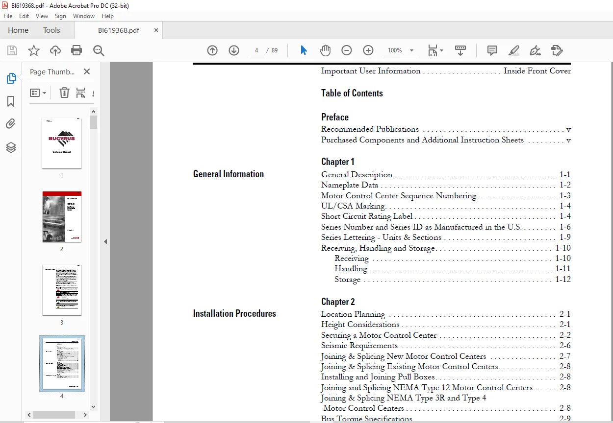
TABLE OF CONTENTS:
Cat Bucyrus CENTERLINE® Low Voltage Motor Control Centers Instruction Manual BI619368 – PDF DOWNLOAD
Preface
Recommended Publications v
Purchased Components and Additional Instruction Sheets v
Chapter 1
General Information General Description 1-1
Nameplate Data 1-2
Motor Control Center Sequence Numbering 1-3
UL/CSA Marking 1-4
Short Circuit Rating Label 1-4
Series Number and Series ID as Manufactured in the U S 1-6
Series Lettering – Units & Sections 1-9
Receiving, Handling and Storage 1-10
Receiving 1-10
Handling 1-11
Storage 1-12
Chapter 2
Installation Procedures Location Planning 2-1
Height Considerations 2-1
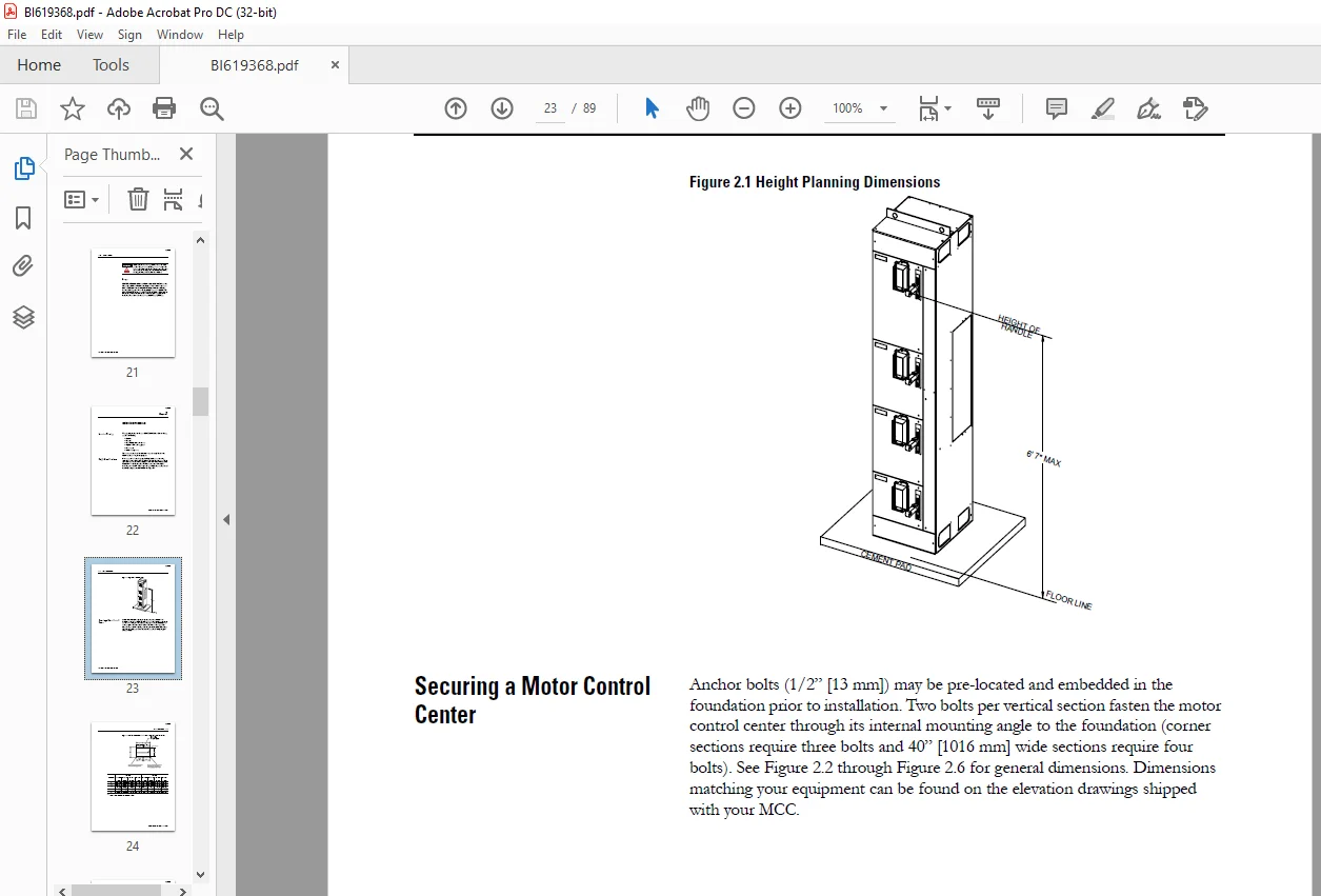
Securing a Motor Control Center 2-2
Seismic Requirements 2-6
Joining & Splicing New Motor Control Centers 2-7
Joining & Splicing Existing Motor Control Centers 2-8
Installing and Joining Pull Boxes 2-8
Joining and Splicing NEMA Type 12 Motor Control Centers 2-8
Joining & Splicing NEMA Type 3R and Type 4
Motor Control Centers 2-8
Bus Torque Specifications 2-9
Chapter 3
Final Checklist Before Energizing Introduction 3-1
Perform a Pre-Energizing Check Procedure 3-1
Pre-Energizing Check Procedure 3-2
BI619368
Publication 2100-IN012B-EN-P – April 2005
ii
Chapter 4
Installing Conduit and Cable Installing Conduit 4-1
Bottom Entry Conduit 4-1
Top Entry Conduit 4-1
Installing Cable 4-2
Lugs 4-2
Incoming Line Compartment 4-2
Main Disconnect 4-3
Cable Bracing 4-3
Incoming Line Brace 4-5
Chapter 5
Installing and Removing Plug-In
Units
Installing Plug-In Units 5-1
Removing Plug-In Unit with a Vertical Operating Handle
from a Section 5-1
Removing Plug-In Unit with a Horizontal Operating Handle
from a Section 5-4
Removing Support Pan 5-6
Chapter 6
Arc Flash Protection Marking as
Required by the National
Electrical Code
Flash Protection Marking Requirement 6-1
110 16 Flash Protection 6-1
Arc Flash Marking Clarification 6-2
Rockwell Automation Assistance 6-2
Chapter 7
Operator Handle and Unit
Interlock
Defeating the Unit Door Interlock 7-1
Opening the Door when the Operating Handle is in the
ON/I Position 7-1
Defeating the Unit Interlock Lever 7-3
Energizing a Unit with the Unit Door Open 7-3
Locking Provisions 7-4
Locking Vertical Operating Handles in the
OFF/O Position 7-4
Locking Horizontal Operating Handles in the
OFF/O Position 7-5
Locking units with Operating Handles in the
ON/I Position 7-5
Unit Interlocks 7-7
Chapter 8
Energizing Equipment Energizing Procedure 8-1
BI619368
Publication 2100-IN012B-EN-P – April 2005
iii
Chapter 9
Maintenance Maintenance Checklist 9-1
Disconnect Switch and Contact Lubrication 9-4
Instructions 9-4
Chapter 10
Maintenance After Fault Condition Maintenace After Fault Condition 10-1
Chapter 11
Renewal Parts Order Information 11-1
Chapter 12
Parts Illustrations Typical Section Construction 12-1
Typical Construction of a Unit with a Vertical
Operating Handle 12-2
Typical Construction of a Half Space Factor Unit with a Horizontal
Operating Handle and Door Mounted Pilot Devices 12-3
Typical Construction of a Unit with a Horizontal
Operating Handle 12-4
Rockwell Automation Support Inside Back Cover
Installation Assistance Inside Back Cover
New Product Satisfaction Return Inside Back Cover
BI619368
Contact us: [email protected]
PLEASE NOTE:
- This is the same manual used by the dealers to diagnose and troubleshoot your vehicle
- You will be directed to the download page as soon as the purchase is completed. The whole payment and downloading process will take anywhere between 2-5 minutes
- Need any other service / repair / parts manual, please feel free to contact [email protected] . We still have 50,000 manuals unlisted
S.V