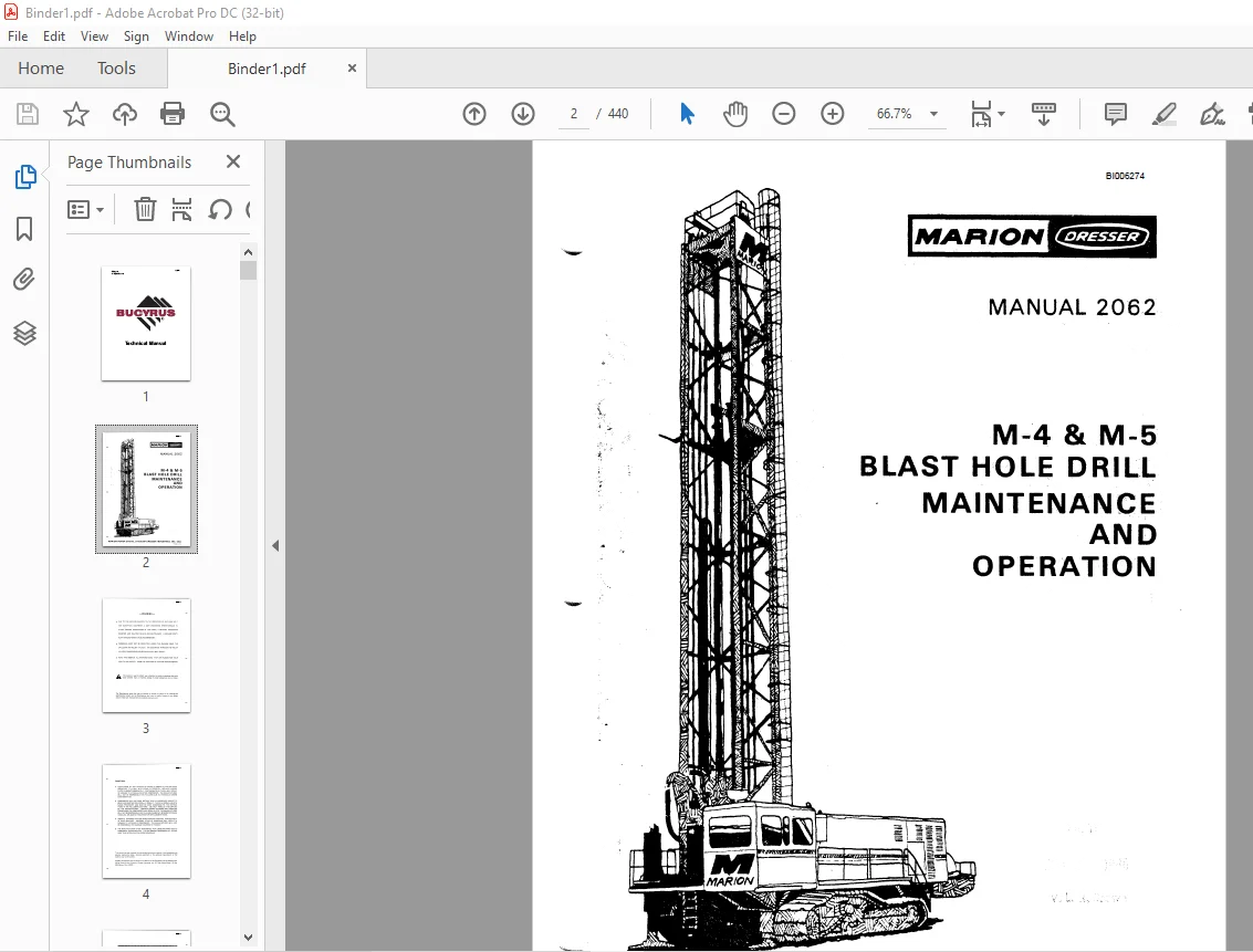
Cat Bucyrus Dresser M-4 & M-5 Blast Hole Drill Maintenance & Operation Manual BI006274 – PDF DOWNLOAD
$29.95
Cat Bucyrus Dresser M-4 & M-5 Blast Hole Drill Maintenance & Operation Manual BI006274 – PDF DOWNLOAD
Description
Cat Bucyrus Dresser M-4 & M-5 Blast Hole Drill Maintenance & Operation Manual BI006274 – PDF DOWNLOAD
FILE DETAILS:
Cat Bucyrus Dresser M-4 & M-5 Blast Hole Drill Maintenance & Operation Manual BI006274 – PDF DOWNLOAD
Language : English
Pages : 440
Downloadable : Yes
File Type : PDF
IMAGES PREVIEW OF THE MANUAL:
DESCRIPTION:
Cat Bucyrus Dresser M-4 & M-5 Blast Hole Drill Maintenance & Operation Manual BI006274 – PDF DOWNLOAD
INTRODUCTION:
The Marion Rotary Blast Hole Drill uses a tri-cone rock bit for the drilling of holes to accept
an explosive material. The denotation of the “charge” breaks the rock and loosens the over
burden. The rotary bit threads to a bit stabilizer or bit sub which threads on to a drill
pipe section that threads into a crossover sub in the rotary gear box and is driven by one
or two direct current electric motor(s) on the rotary gear box in the mast. The rotary
gear box provides torque and rotary speed to the drill bit. A roller chain
hoist-pulldown system, powered by two hydraulic motors, raises and lowers the rotary gear box
and provides a load (or force) to the drill bit.
- The machine is equipped with an independent propel system which uses a hydraulic motor on
each crawler. The operator is afforded control of each crawler separately to permit
excellent machine maneuverability. - The optional automatic (or semi-autolube) lubrication system provides lubrication to critical
parts of the machine when in propel mode. - The drill air compressor(s) uses a rotary vane impeller or two screw rotors to supply
air down thru the drill pipe and thru the drill bit. This bailing air cools the bearings in the
drill bit and removes the drilled material cuttings from the hole. - The auxiliary air compressor provides pressurized air to operate the air valves and
lubrica tion air pump. An additional discharge port is provided for attachment and use of air
tools or hose for cleaning components or machinery house. - The hoist-pulldown and propel hydraulic circuits are included in the main hydraulic system. This
system is powered by a 200 horsepower motor geared to two variable displacement axial
piston pumps. - The auxiliary hydraulic system powers the support functions of the machine.
- A house air filtering system provides clean air to the machinery house to cool the enclosed
components and provide a slight pressurization to keep dust and dirt from entering.
SAFETY SUGGESTIONS:
- The operator controls the machine and its usefulness. The crew alone thinks for it. Safety,
constantly in mind, prevents accidents. Develop good habits. Everyone has bad habits, but
try to erase them quickly. Cleanliness and safety go together. A clean machine is easier
to operate, inspect and maintain. - READ and OBSERVE ALL warning signs, they’re placed for your health and safety. KNOW the location
of fire extinguishers. - DO NOT ORI LL or PROPEL the machine without adequate air pressure.
- DO NOT LEAVE the controls without pushing the OFF BUTTON marked “ROTATION”, turning BOTH
brake switches to “SET” and hoist-pulldown lever to the center detent position. - DO NOT SERVICE or lube moving parts.
- PLEASE READ carefully this Manual, the Parts Book, and other manuals provided. PLEASE LUBE
regularly. - PLEASE CREATE A SYSTEMATIC maintenance procedure and follow it PLEASE WATCH clearance when
lowering mast - PLEASE OPERATE machine on as near level ground as possible PLEASE KEEP safe operating procedures
in mind at ALL times. - CAUTION IS THE BY-WORD. Develop a feel for the machine. Try to sense failure before it
arrives. Take that extra second to look again at something that seems out of place. - A paint chip or bubble may be an early warning. A slight hiss may indicate a growing air leak.
- It’s much easier to tighten a packing nut than shutdown for packing repair.
- PROPERLY GROUND the power source WATCH Al R system performance.
- CHECK pulldown chains for early signs of wear or failure that may cause permanent damage
TABLE OF CONTENTS:
Cat Bucyrus Dresser M-4 & M-5 Blast Hole Drill Maintenance & Operation Manual BI006274 – PDF DOWNLOAD
Introduction 1-1
Safety Suggestions 1-2
Suggestions for Inspection 1-4
Operator’s Cab 2-1
Drill Control Panels 2-3
Annunciator Panel:
Standard Functions 2-7
Optional Functions 2-9
Depth Indicator Display (Optional) 2-10
Automatic Drill Control (ADC) Panel 2-10
Propel Control Stand 2-13
Starting Panel 2-15
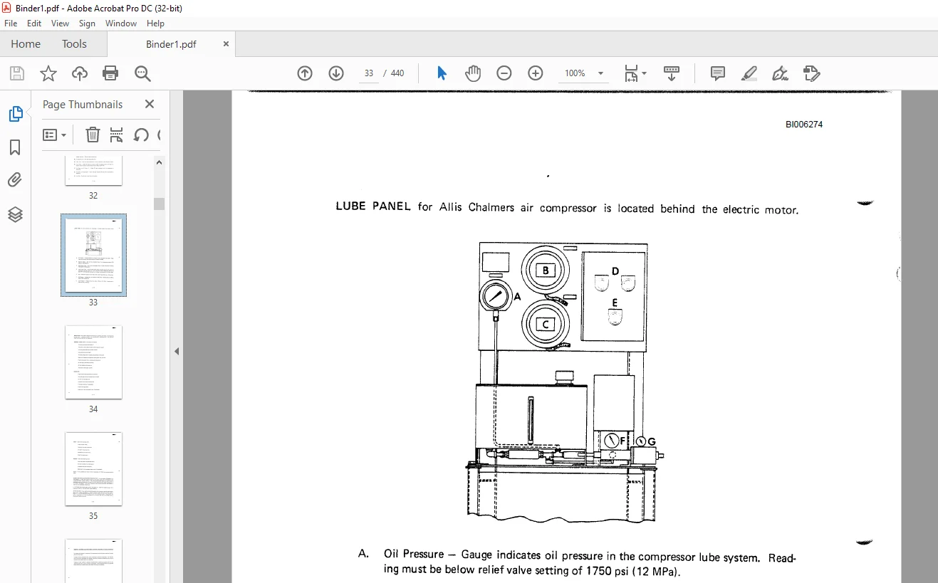
Lube Panel 2-16
Inspection
General Check List 2-17
Crawlers 2-17
Mast 2-18
House 2-18
Guidelines for Cold Weather Pre-Start-up 2-18
Typical Start-up 2-20
Propel Machine 2-22
Section 2 – Operation (cont) Page
Towing 2-22
Self-Propelling 2-22
Propel Stand Operation 2-22
Remote Propel Operation 2-23
Raising Mast 2-24
Lowering Mast 2-25
Machine Leveling 2-25
Required Method of Leveling 2-26
Laterally Leveling 2-26
Retracting Jack 2-26
Assembly of Drill String 2-26
Adding Additional Stem to String 2-28
Remove Drill Stem from String 2-29
Breakout Tong 2-30
Drilling Operation:
Manual Drill Control 2-30
Automatic Drill Control 2-30
To Stop Drilling Operation 2-31
Typical Shut Down 2-31
Crawler Assembly 3-1
Crawler Belt 3-3
Adjust Crawler Belt 3-3
Removing and Replacing Belts 3-4
Load Rollers and Top Rollers 3-4
Propel Gear Case 3-5
Propel Brake 3-7
Hoist/Pull Down Chain 3-9
Gear Box Guide Rollers 3-10
Hoist/Pull Down Machinery 3-11
Hoist/Pull Down Shaft 3-11
Hoist/Pull Down Brake(s) 3-12
Rotary Gear Box 3-13
Assemble Gear Case 3-15
Stem Rack 3-16
Steady Gu ide 3-19
Break Out Tong 3-19
Break Out Tool (Bit Pot) 3-20
Winch 3-20
Section 3 – Machinery (cont.) Page
House Ventilation System 3-20
Electrical Cable Reel 3-21
Cable Reel Drum 3-22
Collector Ring Assembly 3-22
Level Wind Drive Assembly 3-22
Mast Braces 3-26
Bag House 3-27
Maintenance 3-27
Monthly:
Cartridge Removal and Installation 3-28
Replace Individual Bags 3-28
Six Months 3-29
Troubleshooting 3-31
Main Hydraulic System:
Pressure Override 4-1
Crossover Manifold 4-2
Accumulator 4-2
Charge Pressure Switches 4-3
Mode Selection Circuit 4-3
Propel Mode 4-3
Normal Hoist/Pull Down Mode 4-3
Fast Speed Hoist/Pull Down Mode 4-4
Auxiliary Hydraulic System:
Steady Guide Circuits 4-5
Leveling Jacks 4-6
Dual Front Leveling Jacks Circuit (Optional) 4-6
Tong Circuit 4-7
Dust Skirt Circuit 4-7
Mast Raise and Lower Circuit 4-7
Optional Mast/Gear Box Hydraulic Interlock 4-8
Stem Rack Circuit 4-8
Upper Stem Rack Latch 4-9
Hydraulic Stem Care and Maintenance 4-9
New Hydraulic Fluid 4-9
Change Schedule for Hydraulic Fluid .. , , 4-11
Particle Contamination Limits Charts 4-12
Hydraul ic Filters 4-13
Hydraulic Control Valves 4-14
Adjustment of Valves , 4-14
Pressure Setting of Valves (Chart) 4-15
Section 4 – Hydraulic Systems (cont.) Page
Hydrostatic Drive Fluid:
General 4-16
Extreme Operation Conditions 4-16
Selection of Hydraul ic Fluid 4-16
Cost of Hydraulic Fluid , 4-17
Specifications 4-17
MPSD Specification – HDF Hydrostatic Drive Fluid 4-18
Hydrostatic Drive Fluid (HDF) Maintenance 4-20
Hydraulic Troubleshooting 4-22
Troubleshooting the Hydraulic Systems 4-24
Main System Operating Hot < •••••••••••••••• 4-27
Auxiliary System Operating Hot 4-28
Auxiliary System Will Not Build Pressure 4-29
Neutral Difficult or Impossible to Find 4-30
Main System Response Sluggish 4-31
System Functions in One Direction Only 4-32
System Will Not Operate in Either Direction 4-33
Troubleshooting Guide for Tyrone Pumps 4-34
Component Repair and Replacement 4-37
Variable Displacement Axial Piston Pump Assemblies 4-37
Main Pump Replacement 4-37
Main Pump Installation 4-38
Minor Repairs, Variable Displacement Pump 4-39
Replacement of Pump Shaft Seals 4-40
Section 4 – Hydraulic Systems (cont.) Page
Replacement of Charge Pump and Charge Check Valves … 4-42
General Parts Identification, Variable Displacement Pump 4-45
Radial Piston Hydraulic Motor 4-49
Removing Hydraulic Motor 4-49
Valve Assembly Removal and Disassembly 4-49
Crankshaft Removal and Piston Assembly Break Down 4-49
Remove Bearings from Motor 4-50
Cylinder Head Removal 4-50
Crank Case Relief Valve Disassembly 4-50
Component Inspection:
Valves, Pistons and Bores 4-50
Connecting Rod and Crankshaft 4-50
Bearing Inspeetion 4-51
Piston and Valve Seal Rings 4-51
O-Rings 4-51
Shaft Seal 4-51
Retaining Rings 4-51
Socket Cap Screws 4-52
Oldham Coupl ing 4-52
Motor Assembly ” 4-52
Assembling Valve to Motor 4-52
Piston and Connecting Rod Assembling 4-53
Connecting Rod and Crank Case Reassembly into Motor Case 4-54
Setting Crankshaft End Float 4-54
Cylinder Head Refit 4-55
Section 4 – Hydraulic Systems (cont.) Page
Staffa Case Leakage Test 4-55
Tyrone Pump Disassembly 4-56
Assembly Instructions 4-58
Bearing Replacement 4-63
Drill Air (R otary Blade Compressor) 5-1
Rotary Pressure Joint 5-2
Rotary Compressor 5-2
Drill Air Compressor Cooling System 5-3
Rotor and Shaft 5-5
Rotor Blades 5-5
Lubricator 5-5
Storage 5-5
Precautions Before Starting 5-6
Starting Procedures 5-6
Operating Precautions 5-9
Intermittent Service Units 5-9
Blade Protection 5-9
Maintenance (Drill Air Compressor Only):
Maintenance Schedule – 24 Hours 5-10
Maintenance Schedule – 300 Hours 5-10
Maintenance Schedule – 1,000 Hours 5-10
Maintenance Schedule – 4,000 Hours 5-11
Dismantling the Air Compressor 5-11
Reassembly 5-13
Section 5 – Drill Air System (cont.) Page
Air Compressor Clearances:
Total Rotor Float 5-15
Rotor End Clearance 5-15
Net Rotor Float 5-15
Bottom Clearance 5-15
Redoweling 5-1B
Troubleshooting – Air Compressor 5-21
Drill Air , 5-1
Descri ption of Components 5-1
Functional Description 5-1
Oil System, Functional Description 5-2
Discharge System, Functional Description 5-3
Control System, Functional Description 5-6
Start – 0 to 40 PSI (0 to 276 kPa) 5-6
Normal Operating Mode – 40 to 100 PSI (276 to 689 kPa) 5-6
Modulating Mode – 100 to 110 PSI (689 to 758 kPa) 5-7
Unload -In Excess of 110 PSI (758 kPa) Line Pressure 5-7
Air Inlet System, Functional Description 5-7
Instrument Panel Group, Functional Description 5-8
Sullair Series 25 Specifications 5-10
Sullair Series 32 – 24 KT Specifications 5-11
Lubrication Guide – Compressor 5-12
Application Guide , , 5-12
Do Not Mix Types of Oils 5-12
Operation 5-12
Purpose of Controls 5-13
Initial Startup Procedure 5-16
Section 5 – Drill Air System (cont.) Page
Subsequent Startup Procedure 5-16
Shutdown Procedure , 5-16
Maintenance:
General 5-16
Daily Operation 5-17
Maintenance After Initial 50 Hours of Operation 5-17
Maintenance After 1,000 Hours of Operation 5-17
Filter Maintenance 5-17
Separator Maintenance 5-17
Bearing Filter Element Replacement 5-18
Servicing the Main Filter 5-18
Disassembly 5-18
Reassembly 5-9
Air Filter Maintenance 5-19
Air Filter Element Replacement 5-19
Air Filter Element Cleaning ” ” . 5-19
Method 1 – Cleaning the Element by Washing 5-20
Method 2 – Cleaning the Element with Compressed Air 5-20
Element Inspection 5-21
Primary Separator Replacement 5-21
Control System Adjustment 5-21
Minimum Pressure Valve Replacement 5-24
Thermal Valve Maintenance 5-25
Drive Coupling Installation and Alignment 5-26
Step 1, Mount Hubs 5-26
Step 2, Angular Alignment 5-27
Step 3, Parallel Offset Alignment 5-27
Step 4, Flexible Element Installation 5-27
Table 1, Installation Data 5-28
Flow Control Valve Maintenance 5-28
Troubleshooting 5-29
Troubleshooting (Symptom – Probable Cause and Remedy) 5-30
Auxiliary Air System 6-1
Compressor 6-1
Lubricator 6-1
Anti-Freezer 6-2
Air Line Filter 6-2
Filter Pressure Regulator 6-3
Air Valves 6-4
Air Compressor Preventative Maintenance:
Daily 6-4
Weekly 6-4
MonthIy 6-5
LUBRICATION
Lubrication Fittings 7-1
Anti-Friction Bearings 7-1
Enclosed Gear Cases 7-1
Extreme Temperature Operation 7-1
Check List 7-2
Clean and Proper Lubricant 7-3
Lubrication Specifications – Greases 7-4
Lubrication Specifications – Oils 7-4
GL – Gear Lubricants (Oil Type) 7-5
Description of Oil and Grease Classification 7-6
Lubrication of Crawler Mount ., 7-9
Lubrication of Rotary Gear Box and Pull Down 7-9
Lubrication of Stem Rack , , , 7-10
Lubrication of Miscellaneous ” . ” 7-11
Automatic Lubrication System 7-13
Replacement of Auto-Lube Components 7-13
Liquid Capacities of Machine 7-14
Standard Lubrication Installation 7-15
Section 7 – Lubrication (cont.) Page
Adjusting and Mounting of Lincoln Injector 7-16
Minimum Hose Bend Radius 7-16
Assembly of Hose Fittings 7-17
Straight Bronze Sleeve Bushings 8-1
Flange Bushing 8-1
Bushing Life 8-1
Bushing Replacement 8-1
Running Clearance for Bronze Bushings 8-2
Installation of Oil and Grease Seals 8-4
Spl it Seals 8-4
Gear Case Seal 8-5
Installation of Vee Type Grease Seals 8-6
Surface Preparation 8-6
Adhesive Removal 8-6
Adhesive Application 8-6
Cured Splines Disassembly ” 8-7
Involute Spline Assemblies Permanent Fit with Adhesive 8-7
Installing Anti-Friction Bearings on Shaft 8-7
Installation of Shrink Fit Pinions 8-8
Pinion Removal 8-9
Shrink Fit Mounting Data 8-10
Cap Screw (Bolt) Class 8-11
Section 8 – Engineering Data (cont)
–
Page
Tightening Method 8-11
Turn-of-Nut Method 8-11
Torque Method 8-12
Recommended Wiring Method 8-13
Welding Information:
Recommendations for Casting Repairs 8-14
Proper Preparation for Welding 8-16
Material Identification and Symbols of Major Parts 8-18
Welding Specifications 8-19
a-Ring Guide:
Squeeze 8-22
Recovery 8-22
Metal to Metal 8-22
a-Ring Problems 8-23
Poor Installation 8-23
Preparation 8-25
Installation 8-26
Backup Rings 8-26
Basic Things to Remember 8-28
F Type Falk Coupling Installation 8-31
Falk Couplings – Type G and GV
G Type Installation 8-39
GV Type Installation 8-41
Keyless Couplings:
Assembly , 8-42
Removal 8-42
Pressure Equipment 8-43
Finishing and Recommended Fits 8-44
Checking Coupling Alignment 8-44
Solidly Coupled Sets Procedure 8-44
Recommended Torque Values 8-45
Coupl ing AI ignment (Representative Readings) 8-46
Conversion Tables 8-47
ELECTRICAL MAINTENANCE
INDEX
Page
Care of D.C. Motors and Generators 9-1
Brush Installation 9-1
Commutators , 9-2
Never Use Emery Cloth or Emery Paper 9-2
Proper Lubrication 9-3
Feeder Cable 9-4
Power Line Grounding Circuit 9-4
Electrical Troubleshooting:
Preparation 9-5
Investigation 9-5
Performance 9-8
Types of Failures 9-8
Short Circuits 9-9
Trouble Shooting Guide for the Annunciator 9-14
INSPECTION REPORTS
Trouble Free Maintenance or Preventive Maintenance Programs 10-1
Inspection 10-2
Cleaning 10-3
Feeling 10-3
Tightening 10-4
Adjusting 10-4
Lubrication 10-5
Daily, Weekly and Monthly Suggested Inspection Check Lists for Mechanical
and Electrical Maintenance 10-7 thru 10-20
Suggested Maintenance Report Form 10-21
Customer Support: [email protected]
PLEASE NOTE:
- This is the SAME manual used by the dealers to troubleshoot any faults in your vehicle. This can be yours in 2 minutes after the payment is made.
- Contact us at [email protected] should you have any queries before your purchase or that you need any other service / repair / parts operators manual.
S.V