Trusted Business
Verified & Licensed
Virus Free Files
100% Safe Downloads
Secure Payment
SSL Protected
Instant Delivery
Available Immediately
CAT Bucyrus Electric 395-BII Mining Shovel Mechanical Maintenance Manual BI005523 PDF DOWNLOAD
$27.95
CAT Bucyrus Electric 395-BII Mining Shovel Mechanical Maintenance Manual BI005523 PDF DOWNLOAD
Instant PDF Download
Available immediately
Save to Your Device
Download & keep forever
Antivirus Scanned
100% virus-free
Trusted Worldwide
175,000+ customers
Description
CAT Bucyrus Electric 395-BII Mining Shovel Mechanical Maintenance Manual BI005523 PDF DOWNLOAD
FILE DETAILS:
CAT Bucyrus Electric 395-BII Mining Shovel Mechanical Maintenance Manual BI005523 PDF DOWNLOAD
Language : English
Pages : 236
Downloadable : Yes
File Type : PDF
IMAGES PREVIEW OF THE MANUAL:
TABLE OF CONTENTS:
CAT Bucyrus Electric 395-BII Mining Shovel Mechanical Maintenance Manual BI005523 PDF DOWNLOAD
CHAPTER 1 – MECHANICAL MAINTENANCE
Section 1 – MECHANICAL PROCEDURE
General 1
Maintenance Schedules and Reports 1
Safety 2
General 2
In-Operation Maintenance 2
Precautions Before and During Maintenance Work 2
Section 2 – LOWER WORKS
Maintenance Schedules and Reports 1
Safety 2
General 2
In-Operation Maintenance 2
Precautions Before and During Maintenance Work 2
Section 2 – LOWER WORKS
Crawler Belts 5
Take-up Tumbler 8
Upper Rollers 9
Lower Roller Bogies 10
Lower Rollers 10
Drive Tumbler 12
Tumbler Drive Shaft and Gear 13
Transverse Shaft 14
Propel Clutches 15
Clutch Discs 16
Propel Brakes 17
Propel Motor 19
Propel Tach Assembly 21
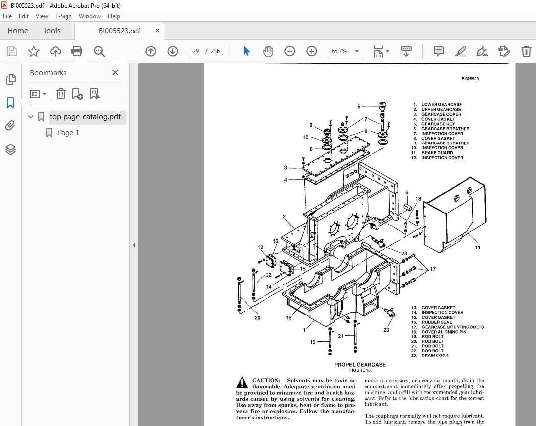
Propel Machinery 22
Crawler Frames and Truck Frame 28
Swing Rack 28
Roller Circle 28
Center Pintle 30
Collector Rings 32
Cable Reel (Optional) 34
Section 3 – ROTATING DECK
Take-up Tumbler 8
Upper Rollers 9
Lower Roller Bogies 10
Lower Rollers 10
Drive Tumbler 12
Tumbler Drive Shaft and Gear 13
Transverse Shaft 14
Propel Clutches 15
Clutch Discs 16
Propel Brakes 17
Propel Motor 19
Propel Tach Assembly 21
Propel Machinery 22
Crawler Frames and Truck Frame 28
Swing Rack 28
Roller Circle 28
Center Pintle 30
Collector Rings 32
Cable Reel (Optional) 34
Section 3 – ROTATING DECK
Revolving Frame 36
Deck Machinery 36
Hoist Machinery 36
Gear Train 36
Hoist Gear and Drum 38
Hoist Brake 39
Hoist Limit Switch (Optional) 41
Hoist Motor 42
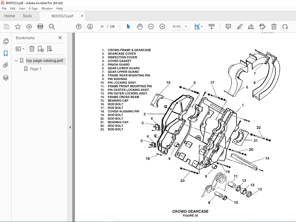
Crowd Machinery 43
Gear Train 43
Crowd Motor 46
Crowd Brake 47
Crowd Gear and Drum 49
Crowd and Retract Limit Switch (Optional) 49
Swing Machinery 50
Gear Train 50
Swing Motor 56
Swing Brake 37
Machinery House 58
House Fans 59
Dynavane Air Cleaner 60
Walkways 60
Operator’s Cabin 61
Seat 61
Windshield Wipers 61
Windshield Washer 63
Retractable Boarding Stair 64
Section 4 – FRONT END EQUIPMENT
Deck Machinery 36
Hoist Machinery 36
Gear Train 36
Hoist Gear and Drum 38
Hoist Brake 39
Hoist Limit Switch (Optional) 41
Hoist Motor 42
Crowd Machinery 43
Gear Train 43
Crowd Motor 46
Crowd Brake 47
Crowd Gear and Drum 49
Crowd and Retract Limit Switch (Optional) 49
Swing Machinery 50
Gear Train 50
Swing Motor 56
Swing Brake 37
Machinery House 58
House Fans 59
Dynavane Air Cleaner 60
Walkways 60
Operator’s Cabin 61
Seat 61
Windshield Wipers 61
Windshield Washer 63
Retractable Boarding Stair 64
Section 4 – FRONT END EQUIPMENT
Boom 65
Boom Point Sheaves 65
Boom Bumpers 66
Saddle Block 66
Dipper Handle 68
Dipper Handle Removal 68
Retract Take-up Mechanism Removal 68
Front Stop and Spreader Removal 68
Crowd Cushion (with Pre-assembled Cushion Stack) 70
Dipper 73
Dipper Padlock 73
Dipper Trip Assembly 75
A-Frame 76
Boom Structural Strands 77
Wire Running Ropes 77
Inspection 77
Hoist Rope Reeving 77
Retract Rope Reeving 80
Crowd Rope Reeving 81
Dipper Trip Reeving 82
CHAPTER 2 – AIR SYSTEM
Section 1 – GENERAL MAINTENANCE
Safety 83
General 83
Air Compressor (Quincy QSB:20) 85
Air Lines 86
Air Line Lubricator 86
Air Line Filter 86
Air Line Regulator 86
Tanner De-leer (Optional) 87
Air/Lube Swivel Assembly 87
Pressure Switches 87
Section 2 – COMPONENT MAINTENANCE
Air Compressor (Quincy QSB20) 89
Air Line Filter 86
Air Line Regulator 86
Tanner De-leer (Optional) 87
Air/Lube Swivel Assembly 87
Pressure Switches 87
Section 2 – COMPONENT MAINTENANCE
Air Compressor (Quincy QSB20) 89
Compressor Operation 92
Starting the Compressor 93
Stopping the Compressor 93
Demeanor for Maintenance or Service 93
Service 93
Assembly and Disassembly of Common Wearing Parts 95
Drive Belt Replacement 97
Air Lube Swivel Assembly Removal 99
Air 99
CHAPTER 3 – LUBRICATION
Section 1 – GENERAL LUBRICATION
Lower Works 102
Rotating Deck 102
Front End 103
Lubrication Bench Marks 103
Multi-Purpose Type Grease (MPG) 103
Air Compressor (Piston Type) Lubricant (CPL) 104
Multi-Purpose Oil (MPO) 106
Open Gear Lubricant (OGL) 106
Regular Type Gear Lubricant (RGL) 107
Roller Circle Rail and Lubricant (RCRL) 109
Running Wire Rope Lubricant (RWRL) 111
Structural Strand and Stationary Wire Rope Lubricant (SWRL) 113
Lubrication Charts 114
Section 2 – AUTOMATIC LUBRICATION SYSTEMS
Inspection 119
Lube System 119
Air Pump Service 120
Lines and Control Service 120
Injectors and Spray Nozzles 121
Startup of Automatic Lubrication Systems 122
CHAPTER 4 – TROUBLESHOOTING
Lube System 119
Air Pump Service 120
Lines and Control Service 120
Injectors and Spray Nozzles 121
Startup of Automatic Lubrication Systems 122
CHAPTER 4 – TROUBLESHOOTING
Section 1 – LOWER WORKS
Crawler 125
3rd Intermediate Propel Shaft 131
2nd Intermediate Propel Shaft 132
1st Intermediate Propel Shaft 132
Propel Rotor Shaft 133
Propel Clutch 135
Propel Brake 135
Propel Motor, Blower, and Gear Case 137
Swing Rack Teeth 137
House Runner Rails 138
House Rollers 138
Center Pintle 139
Section 2 – ROTATING DECK
Hoist Machinery 141
Hoist Motor Pinion Shaft 141
Hoist Intermediate Shaft Assembly 142
Hoist Drum Assembly 143
Crowd Machinery 145
Crowd Drum Gear and Pinion Lubrication 146
Crowd Disc Type Brake 148
A-Frame 148
Swing Machinery 149
Section 3 – FRONT END EQUIPMENT
Hoist Motor Pinion Shaft 141
Hoist Intermediate Shaft Assembly 142
Hoist Drum Assembly 143
Crowd Machinery 145
Crowd Drum Gear and Pinion Lubrication 146
Crowd Disc Type Brake 148
A-Frame 148
Swing Machinery 149
Section 3 – FRONT END EQUIPMENT
Boom 153
Dippers – Pin Connected 156
Dipper Door Snubbers 157
Dipper Handle 158
Air/Lube Swivel 159
Section 4 – AIR SYSTEM
Dippers – Pin Connected 156
Dipper Door Snubbers 157
Dipper Handle 158
Air/Lube Swivel 159
Section 4 – AIR SYSTEM
Quincy QSB20 Screw Compressor 163
APPENDICES
APPENDICES
Appendix A1 – GEAR INSPECTION 169
Appendix A2 – BOLT TORQUING
Torque Wrench Method 171
Turn-Off-The-Nut Method 172
Appendix A3 – MAINTENANCE WELDING
Principal Structures 173
General 173
Maintenance Welding 173
Structural Materials 174
Welding Electrodes 174
Preheat Requirements 177
Removal of Cracks 178
Weld Groove Preparation 178
Butter Welding 178
Welding Technique 178
Weld Inspection 179
Repair of Broken Parts 180
Dipper Handles 180
Maintenance Welding 180
Flame Straightening Bent Tube 180
VIDEO PRVIEW:
https://vimeo.com/857068044?share=copy
DESCRIPTION:
CAT Bucyrus Electric 395-BII Mining Shovel Mechanical Maintenance Manual BI005523 PDF DOWNLOAD
FOREWORD
The purpose of this manual is to provide information concerning the general maintenance of the 395-B electric mining shovel. The Model 395-B consists of three major units, the lower works, the rotating deck and the front end equipment. The lower works provides a foundation for the revolving frame and contains the necessary equipment to propel the shovel.
- The rotating deck includes the revolving frame, ballast box, and machinery house The machinery house encloses all ofthe hoist, swing and crowd machinery, and the electrical systems required to control machine functions.
- It also contains an air filtration system to minimize heat and dirt build-up in the machinery house. An elevated cab mounted on the house provides the machinery operator’s station.
- The cab contains all machine operating controls. The front end equipment is comprised of the A-frame, dipper, dipper handle, boom, running ropes, and boom structural strands.
- This manual consists of five chapters, each divided into sections. A table of contents precedes each chapter.
- Throughout this manual the words CAUTION, WARNING and NOTE appear in bold face type. CAUTION is preceded by the safety alert symbol A and indicates that injury to personnel could occur if the proper procedures are not followed during operation or maintenance.
- Always read the CAUTION note carefully and use extreme care while performing that particular function.
- WARNINGindicates a possible hazard to the machine or its components ifthe proper procedures are not followed.
- Whenever the word WARNING appears, special attention should be given to prevent possible equipment damage. NOTE is used to stress a point or to give additional information concerning the procedure being discussed.
- These CAUTION’s and WARNING’s are not all-inclusive. It is impossible for Bucyrus-Erie Company to know, evaluate, and advise maintenance and service personnel in every conceivable way a service operation might be performed and of the resulting possible hazardous consequences of each method.
- It is therefore extremely important that anyone who uses a service procedure or tool which is not recommended by Bucyrus-Erie Company to first satisfy himself that the service procedure or tool he chooses will not jeopardize his own safety, the safety of others, or cause machine or component damage.
PLEASE NOTE:
- This is the same manual used by the dealers to diagnose and troubleshoot your vehicle
- You will be directed to the download page as soon as the purchase is completed. The whole payment and downloading process will take anywhere between 2-5 minutes
- Need any other service / repair / parts manual, please feel free to contact [email protected] . We still have 50,000 manuals unlisted
G.P