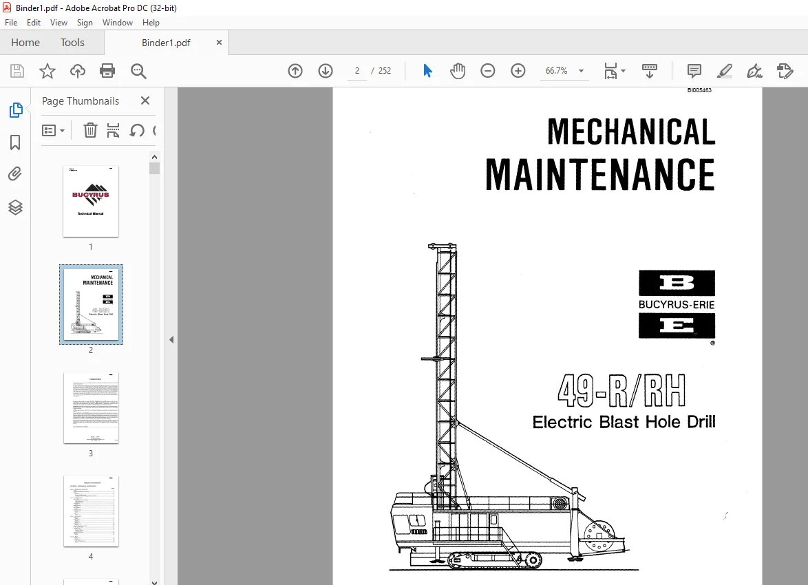
CAT BUCYRUS-ERIE 49-R RH Electric Blast Hole Drill MECHANICAL MAINTENANCE MANUAL BI005463 – PDF DOWNLOAD
$28.95
CAT BUCYRUS-ERIE 49-R RH Electric Blast Hole Drill MECHANICAL MAINTENANCE MANUAL BI005463 – PDF DOWNLOAD
Description
CAT BUCYRUS-ERIE 49-R RH Electric Blast Hole Drill MECHANICAL MAINTENANCE MANUAL BI005463 – PDF DOWNLOAD
FILE DETAILS:
CAT BUCYRUS-ERIE 49-R RH Electric Blast Hole Drill MECHANICAL MAINTENANCE MANUAL BI005463 – PDF DOWNLOAD
Language : English
Pages :252
Downloadable : Yes
File Type : PDF
DESCRIPTION:
CAT BUCYRUS-ERIE 49-R RH Electric Blast Hole Drill MECHANICAL MAINTENANCE MANUAL BI005463 – PDF DOWNLOAD
- FOREWORD
- The purpose of this manual is to provide information concerning the general maintenance of the 49-R rotary blast hole drill. The 49-R consists of three major units, the lower works, the mainframe and the mast. The lower works provides a foundation for the mainframe and contains the equipment necessary to propel the drill.
- The mainframe includes the hydraulic, main air and auxiliary air systems, and the machinery house. The machinery house encloses the majority of the mechanical equipment necessary for the main and auxiliary air systems, the hydraulic systems and electrical control systems.
- The machinery house is pressurized with filtered air to minimize dirt and heat build-up. The operator’s cab, mounted to the mainframe, provides the operator’s station, and enclosed the majority ofthe controls necessary to operate the drill. The mast contains the drill pipe and drilling tools, the pipe racks and the rotary and pulldown machinery. This manual consists ofsix chapters, each divided into sections. A table ofcontents is located in the front of the manual.
IMAGES PREVIEW OF THE MANUAL:


TABLE OF CONTENTS:
CAT BUCYRUS-ERIE Electric Blast Hole Drill MECHANICAL MAINTENANCE MANUAL BI005463 – PDF DOWNLOAD
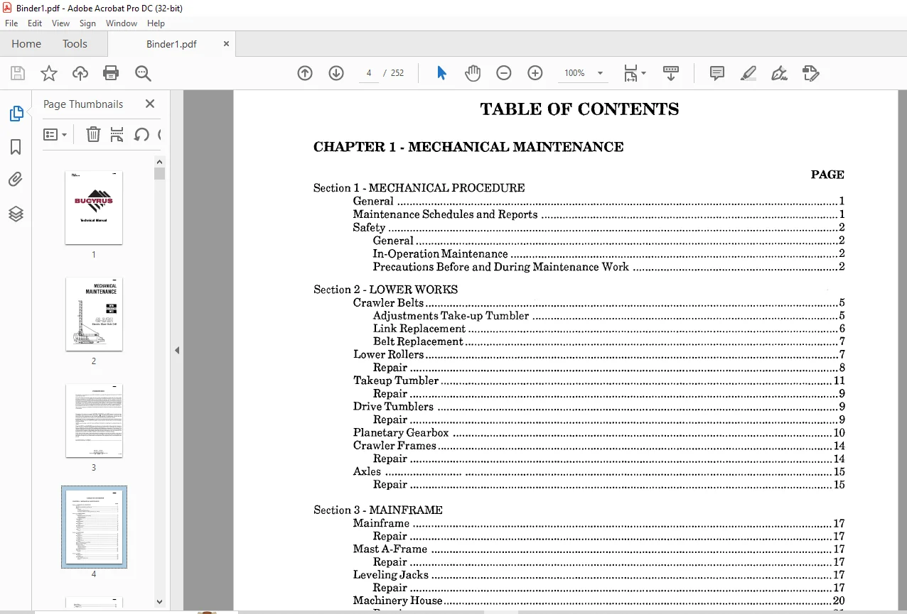
Section 1 – MECHANICAL PROCEDURE
General 1
Maintenance Schedules and Reports 1
Safety 2
General 2
In-Operation Maintenance 2
Precautions Before and During Maintenance Work 2
Section 2 – LOWER WORKS
Crawler Belts , 5
Adjustments Take-up Tumbler 5
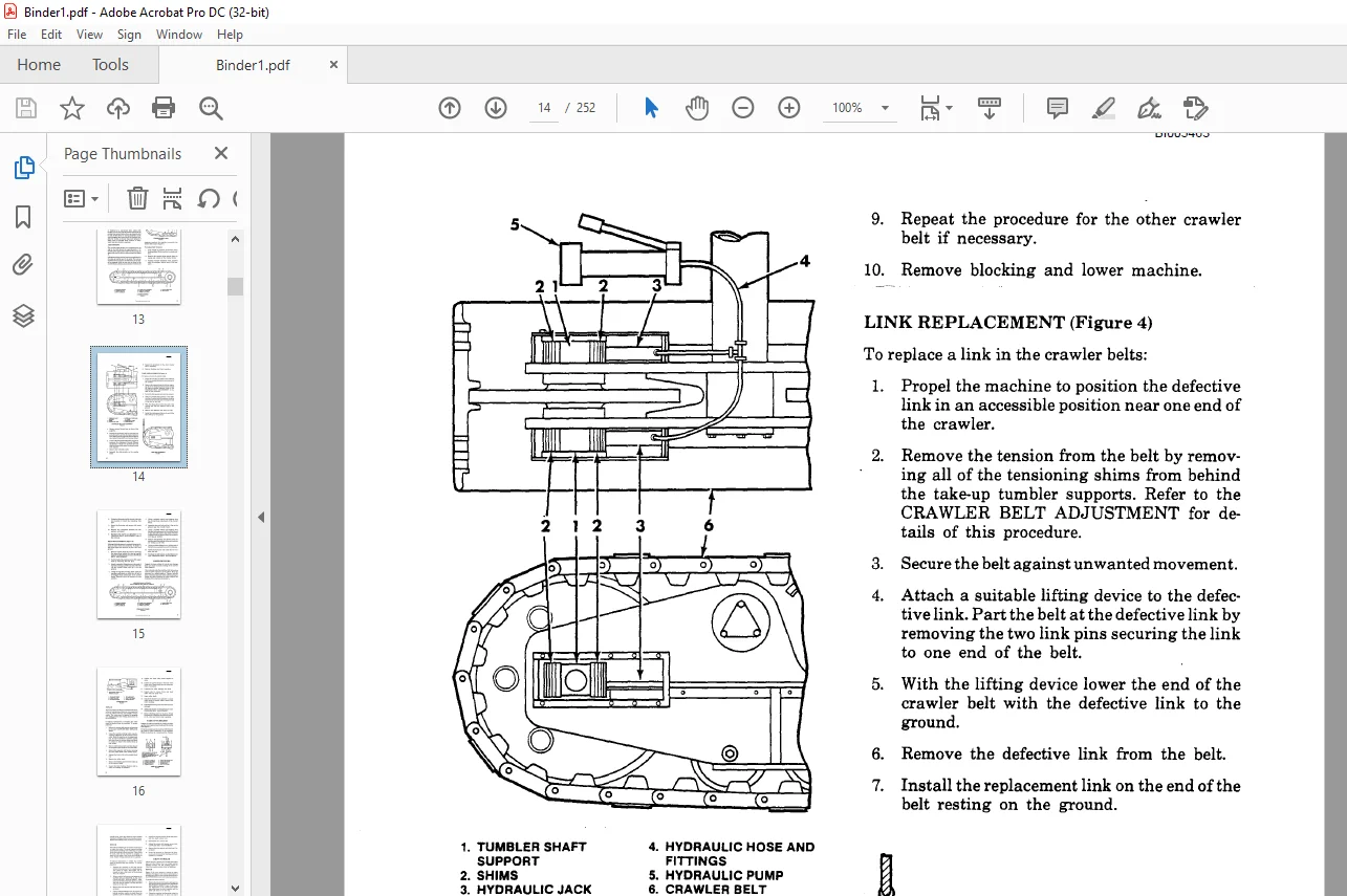
Link Replacement 6
Belt Replacement 7
Lower Rollers 7
Repair 8
Takeup Tumbler 11
Repair 9
Drive Tumblers 9
Repair 9
Planetary Gearbox 10
Crawler Frames 14
Repair 14
Axles 15
Repair 15
Section 3 – MAINFRAME
Mainframe 17
Repair 17
Mast A-Frame 17
Repair 17
Leveling Jacks 17
Repair 17
Machinery House 20
Repair 21
House Ventilation Fan and Filter 21
Walkways and Ladders 21
Operator’s Cab 22
Operator’s Seat ;22
Operator’s Controls
Ventilation Unit 22
Hydraulic Pump Drive 22
Cable Reel 24
Repair 25
Section 4 – MAST
Mast Structure 29
Repair 29
Rotary Gearcase 30
Drive Shaft Adjustment 30
Repair 30
BI005463
Rotary Motor ., 34
Rotary Coupling 34
Repair 34
Rotary Shock Sub 35
Repair 36
Rotary/Pulldown Guide Frame 36
Guide Roller Adjustment 36
Repair 38
Pulldown Gearcase 40
Repair 40
Hoist Brake 44
Inspection 44
Adjustment 44
Repair 44
Pipe Racks 46
Repair 46
Tool Wrenches 46
Repair 48
Casing Tong Support 49
Pipe Positioner 49
Auxiliary Winch 51
Mast Braces 52
Repair 52
Adjustment 52
CHAPTER 2 – HYDRAULIC SYSTEM
Section 1 – SYSTEM OPERATION
Cylinder Circuit Hydraulic System 55
Propel Circuit Hydraulic System 56
Section 2 – GENERAL MAINTENANCE
Hydraulic System Cleanliness 63
Oil Requirements 63
Oil and Filter Changes 63
Weekly Maintenance Checks 63
Oil Reservoir Repairs 64
Prestart Inspection 64
Hydraulic System Tests 64
Propel Pump Charge Pressure (Rexroth Pumps only) 64
Propel Pump Charge Pressure (Sundstrand Pumps only) 64
Control Pressure Check 65
Propel Enable Valve and High Speed Select Check 65
Jack Cylinder Check In Manual Mode 65
Propel Brake Release Pressure Check 66
Left Track Main Relief Pressure Check (Rexroth Pumps only) 66
Left Track Main Relief Pressure Check (Sundstrand Pumps only) 67
Left Track Pressure Override Check (Rexroth Pumps only) 67
Left Crawler Track Sprocket RPM Check (Sundstrand Pumps only) 67
Right Track Main ReliefPressure Check (Rexroth Pumps only) 68
Right Track Main ReliefPressure Check (Sundstrand Pumps only) 68
Right Track Pressure Override Check (Rexroth Pumps only) 68
Right Crawler Track Sprocket RPM (Sundstrand Pumps only) 69
Propel Brake Emergency Release Check 69
Mast Latch Cylinders 69
BI005463
Dust Curtain Cylinders 69
A-Frame Latch Cylinders 69
Mast Brace Latch Cylinders 69
Mast Hoist 70
Auxiliary Winch 70
Pipe Rack Position 70
Pipe Rack Lock and Gate Cylinder Port ReliefSetting 70A
Cable Reel 70A
Leveling Jacks In Auto Level Mode 70A
Test Point Location Chart 70B
Section 3 -COMPONENTMAINTENANCE
Cylinder Circuit Hydraulic Pump Overhaul 71
General 71
Single Pump Disassembly 71
Singe Pump Inspection 72
Single Pump Assembly 73
Dual Pump Disassembly 74
Dual Pump Inspection 75
Dual Pump Assembly 75
Cable Reel Hydraulic Pump 77
General 77
Disassembly 78
Inspection 79
Assembly 79
Cable Reel Hydraulic Motor 79
Disassembly 79
Cleaning and Inspection 81
Reassembly 81
Hydraulic Oil Cooler ‘” 82
Weekly Maintenance Check 82
1000 Hour Maintenance Check 82
Yearly Maintenance Check 82
CHAPTER 3 . AIR SYSTEMS
Section 1 – SYSTEMS OPERATIONS
General 83
Main Air System 83
Auxiliary Air System 83
Safety 83
Section 2 – GENERAL MAINTENANCE
Main Air System 87
General 87
Intake Air Filter – Box Type 87
Intake Air Filter – Tubular Type 87
Compressor Radiator 88
Auxiliary Air System 88
Auxiliary Air Compressor 88
Miscellaneous Components 89
Unloader Check Valve Service 89
Air Tanks 90
Air Tank Valves 90
Pressure Switch 90
Filter 90
Anti-Freezer 90
BI005463
Section 3 – AUXILIARY AIR COMPRESSOR (COMPAIR-KELLOGG) B352
Disassembly 91
Fitting and REassembly 92
Section 4 – AUXILIARY AIR COMPRESSOR (COMPAIR-KELLOGG) B462
Head Value Service 95
Piston Ring Service 95
Overhaul Procedure 96
Reassembly 96
Section 5 -ROTARY VANE COMPRESSOR (A-C COMPRESSOR CORP.)
1000 Hour Maintenance Check 99
4000 Hour Maintenance Check 100
Blade Protection in Idle Units 102
Rotor Alignment for Redoweling 102
Rotor Field Redoweling 103
Section 6 – ROTARY SCREW COMPRESSOR (A-C COMPRESSOR CORP.)
Description 105
Coupling Alignment , 105
Start-Up Procedure 106
Controls and Instruments 107
Lubrication System 113
Air Filters 119
Maintenance Schedule 120
CHAPTER 4 . TROUBLESHOOTING
Section 1 – GENERAL MAINTENANCE
Drilling Platforms and Dust Curtains 127
Filter/Clone® System (Tipton) , 127
Daily Maintenance , ‘” .127
Monthly Maintenance Checks 127
Six Month Maintenance Checks 127
Water Injection , ‘” 128
Operation 128
Section 2 – MAINTENANCE OF FILTER/CLONE® (TIPTON)
OperatingPrinciples 129
Maintenance 129
CHAPTER 5 . LUBRICATION
Section 1 – LUBRICATION
General 131
Lubricant Cleanliness 131
Lubrication Points 131
Lubricant Benchmarks 132
Lubrication Charts
Gearcase and Reservoir Capacities 132
Lower Works 133
Mainframe 134
Mast (Part 1) 135
Mast (Part 2) 136
Mast (Part 3) 137
BI005463
Section 2 – LINCOLN AUTOMATIC SYSTEM
Troubleshooting Systems 139
Air Locks 139
Dirty Supply Lines 139
All Injectors Do Not Function Properly 139
Mter Venting, the Indicator Stems on the Injectors
Do Not Return to Their Normal Position 139
Failure ofPump to Build Up Pressure 140
Sluggish Pump Operation 140
Slow Pressure Rise 140
Assembly ofTubing Compression Fittings 140
Principle of Operation – Pump Air Motor 140
Service ofLower Pumping Unit 142
Lubrication 143
Installation, Operating, and Maintenance Instructions 143
Section 3 – TRABON AUTOMATIC SYSTEM
Locating Blockage in System 147
Terminology 147
Procedure 147
Torque Information in Foot Pounds 150
Section 4 – VANE TYPE MAIN COMPRESSOR LUBRICATOR
Operation and Adjustment 151
To Start Lubricator 151
To Adjust Lubricator 151
Sight Feed Unit 151
Purging Oil From Pumping Unit 151
Care of Lubricator 152
CHAPTER 6 – TROUBLESHOOTING
General 153
Drilling 153
Rotary Drive Unit 155
Pulldown Unit 156
Pulldown Unit Hoist Brake 158
Mast 158
Main Air Compressor (vane type) 159
Main Air Compressor (screw type) 161
Auxiliary Air Compressor 164
Hydraulic System 165
Hydraulic Oil Cooler 166
Hydraulic Cylinder 167
Hydraulic Pump (Cylinder Circuit) 167
Hydraulic Pump (Propel Circuit)
Cable Reel Hydraulic Motor 169
Filter/Clone® 170
BI005463
APPENDICES
Appendix Al – GEAR INSPECTION IA
AppendixA2 – BOLT TORQUING
Torque Wrench Method 3A
Turn-Of-The-Nut Method 4A
Appendix A3 – PINION, BRAKE DRUM, AND COUPLING INSTALLATION
Removal From Motor Shaft 5A
Mounting on Shaft 5A
Appendix A4 – LUBE BENCHMARKS
Multipurpose Type Grease (MPG) 9A
Air Compressor (vane type) Lubricant (ACVL) lOA
Air Compressor (screw type) Lubricant (ACSL) llA
Chain Drive Lubricant , 12A
Drill Pipe Thread Lubricant (DPTL) 13A
Multipurpose Oil (MFO) 14A
Open Gear Lubricant (OGL) 14A
Regular Type Gear Lubricant (RGL) 16A
Running Wire Rope Lubricant (RWRL) 20A
Hydraulic Oil (lIYDO) 2IA
Appendix A5 -RECOMMENDED PROCEDURES FOR MAINTENANCE WELDING OR
PRINCIPAL STRUCTURES ON BLAST HOLE DRILLS
General 23A
Maintenance Welding 23A
Structural Materials 23A
Welding Electrodes 24A
Preheat Requirements 26A
Removal ofCracks 26A
Weld Groove Preparation 26A
Drill Pipe Welding 26A
Welding Technique 28A
Weld Inspection 28A
Repair ofBroken Parts 28A
Methods ofRepair of Cracks 28A
Appendix A6 – PREVENTIVE MAINTENANCE CHECKLISTS
Level I Inspection 29A
Level II Inspection 34A
Level III Inspection 36A
Appendix A7 – SPECIAL DRAWINGS (BEARING FITS)
Pulldown First Intermediate and Shipper Shaft 39A
Pulldown Input Shaft 39A
Pulldown Second Intermediate Shaft 39A
Rotary Gearcase Shafts 40A
Lower Guide Rollers 4IA
Upper Guide Rollers and Shipper Shafts .4IA
Need help? Contact: [email protected]
PLEASE NOTE:
- This is the SAME exact manual used by your dealers to fix your vehicle.
- The same can be yours in the next 2-3 mins as you will be directed to the download page immediately after paying for the manual.
- Any queries / doubts regarding your purchase, please feel free to contact [email protected]
S.M