Cat Bucyrus Gardner Denver RDC-16B Maintenance Instruction Manual BI009315 – PDF DOWNLOAD
$28.95
Cat Bucyrus Gardner Denver RDC-16B Maintenance Instruction Manual BI009315 – PDF DOWNLOAD
Description
Cat Bucyrus Gardner Denver RDC-16B Maintenance Instruction Manual BI009315 – PDF DOWNLOAD
FILE DETAILS:
Cat Bucyrus Gardner Denver RDC-16B Maintenance Instruction Manual BI009315 – PDF DOWNLOAD
Language : English
Pages : 208
Downloadable : Yes
File Type : PDF
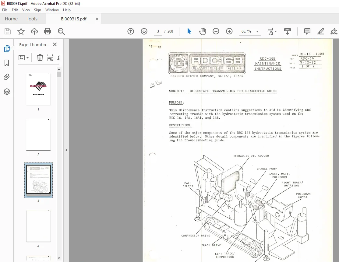
DESCRIPTION:
Cat Bucyrus Gardner Denver RDC-16B Maintenance Instruction Manual BI009315 – PDF DOWNLOAD
Note 1.To check relief valve setting:
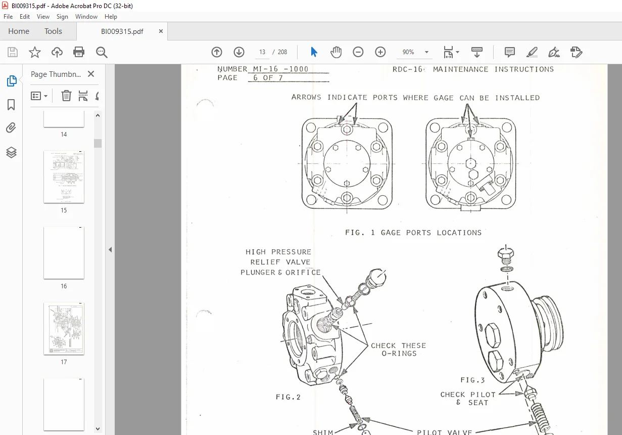
a.Install 0-6000 psig hydraulic gage in ports indicated in figure 1, or tee located in front of
hydraulic pumps.
b. Start engine. Lock tracks by pumping hydraulic hand pump.
c.Place left pump control in forward tram position (selector valve should be in tram position).
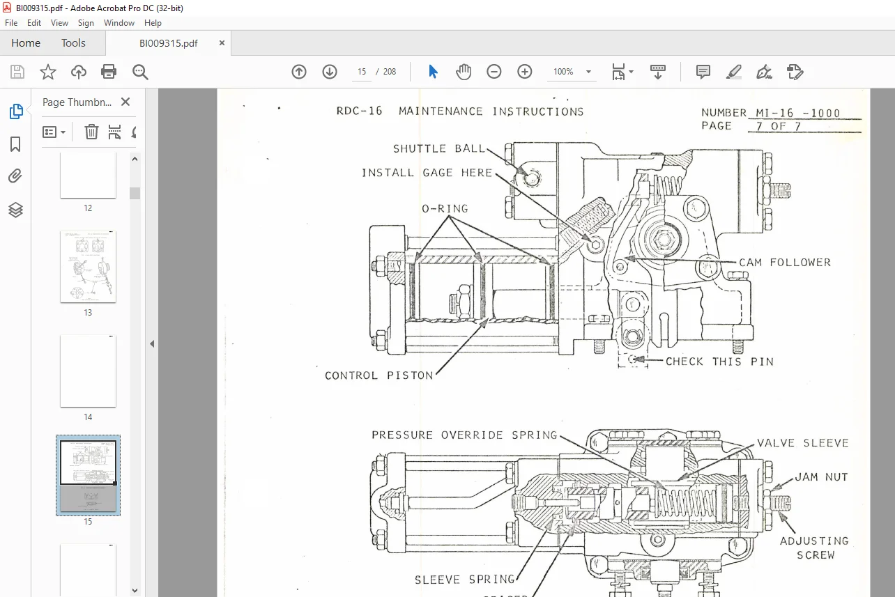
d. Loosen jam nut on pump compensator control (see figure 5). Turn adjusting screw clockwise,
readir.g pressure on gage . Highest pressure obtained will be relief valve setting. Do not exceed
5500 psig,
e.Return pump compensator setting to nameplate setting on control.
f.If relief valve was not set per pump housing nameplate, add shims as shown in figures 2 and 3 (.001
per SO psig increase desired).
Note 2.Manufacturer specifies that charge pump pressure should be 25 psig per 1000 psig operating
pressure. A 4000 psig system should have a minimum 100 psig charge pump pressure to maintain
control of functions. Pressure may be checked by installing gage to tee on hydraulic pump relief
valve package (see figures 3 and 4).
Note 3.To check case drain flow (leakage):
a.Lock tracks.
b. Operate unit suspected as malfunctioning at full pressure, maximum rpm.
c.Disconnect case drain line and place in 5-gallon bucket or other container of known capacity. Note
length of time required to fill container.
d. Units with case drain flow in excess of 3 gpm should be replaced. Normal unit
should drain up to 1.5 gpm maximum.
IMAGES PREVIEW OF THE MANUAL:
Questions? Email us: [email protected]
PLEASE NOTE:
- This is the same manual used by the dealers to diagnose and troubleshoot your vehicle
- You will be directed to the download page as soon as the purchase is completed. The whole payment and downloading process will take anywhere between 2-5 minutes
- Need any other service / repair / parts manual, please feel free to contact [email protected] . We still have 50,000 manuals unlisted
S.V