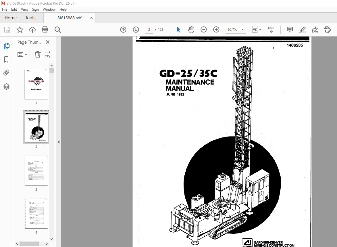
CAT BUCYRUS GD-25 GD-35C ROTARY BLABTHDLE MAINTENANCE MANUAL 1406535 -PDF DOWNLOAD
$19.95
CAT BUCYRUS GD-25 GD-35C ROTARY BLABTHDLE MAINTENANCE MANUAL 1406535 -PDF DOWNLOAD
Description
CAT BUCYRUS GD-25 GD-35C ROTARY BLABTHDLE MAINTENANCE MANUAL 1406535 -PDF DOWNLOAD
FILE DETAILS:
CAT BUCYRUS GD-25 GD-35C ROTARY BLABTHDLE MAINTENANCE MANUAL 1406535 -PDF DOWNLOAD
Language : English
Pages :123
Downloadable : Yes
File Type : PDF
DESCRIPTION:
CAT BUCYRUS GD-25 GD-35C ROTARY BLABTHDLE MAINTENANCE MANUAL 1406535 -PDF DOWNLOAD
Introduction
1. ASSOCIATED PUBLICATIONS
There are two related publications furnished with the GD-25/35C Rotary Blasthole Drill. Both are listed below and are referenced in this manual.
GD-25/35C Rotary Blasthole Drill Operator Manual
GD-25/35C Rotary Blasthole Drill Parts Manual
2. NOTES, CAUTIONS, AND WARNINGS
Notes, cautions, and warnings are included where appropriate in this manual. Definitiol’.15 for each term are.explained below, followed by a surmary of general warnings and cautions.
IMAGES PREVIEW OF THE MANUAL:


TABLE OF CONTENTS:
CAT BUCYRUS GD-25 GD-35C ROTARY BLABTHDLE MAINTENANCE MANUAL 1406535 -PDF DOWNLOAD
List of Illustrations vi
List of Tables · · viii
Section I
General
SCOI)e:
Description
Engine, Pllllps, and Compressor
Pulldown and Drilling Systems
Tramnil”lg System
Control System
Controls and Indicators –
Technical Characteristics
Introduction ; :
Drilling Equipnent
PiE)e Rack :
Pipe Carousel ,
Slant Drillfrg_
Drill Pi-pe –
Drilling Lights
Weather Protection
Cold weather –
Hot weather ~
Engine Related
Ether Injection
Water Injection
Section III
Theory
System
Open Loop System
Four Spool Valve Bank Circuits ·
Seven Spool Valve Bank Circuits
Pipe Indexing Circuit (Optional)
Return Circuit · · ·
Closed t oop System
PLUn~
Selector Valves
Tram/Drill Control Valves ~
Motors
Pulldo\llt’l A dj ust
Air System
compressor
Reservoir
Section IV
Troubleshooting
Introduc~ion , ,
Preliminary Checks · · · ·
Carmon Systems
References
Operatil’lC1 Systems
Section V
Maintenance Procedures
Introduction · ·
conunon Procedures ~
Bleedillg Cylinders
Priming 1?lJR\ps
Pressure Measurements
Flushing Hydraulic System
Good Repair Practices
Welding Procedures
Closed Loop P\Jnps
Normal Conditions
· Repair/Replacement
Adjustments
Rotary Drive
Normal Conditions
Repair/Replacement
Adj llStlnents
PulldOWl’l System
Normal Conditions
Repair/ReplacE!IU8nt –
Adjustments
Track Drive System
Normal Conditions
Repair/Replacement
AdjtJStrnents
0peri Loop Plltlp
Normal Conditions
Repair/Replacement ·
Adjustments
Main Jacks
Normal Conditions
Repair/Replacement ;
MjtJStrnents
Breakout Equipnent
Normal Conditions
Repair/Replacement ·
Mj llStrnents
Mast Jacks
Normal Conditions
Repair/Replacement
Adjustments
Winch
Normal Conditions
Repai r/Replacernent
Adjustments
Air System
Normal Col’lditions
Repair/Replacement · ·
Adjustments
Clutch and Gearbox
Normal Conditions · · ·
Repair/Replacement ·
A dj llStrnents
Pi i:,e Carousel
Normal Conditions · · · · · ·
R~pair/Replacement ·
Adj 1JStntents
Pil:H! Rack
Normal Conditions· · · ·
Repair/Replacement· · ·
A djllStinents ~
Optional 3eaters
electric Circuits
Miscellaneous Components ·
General
GD-25/35C Rotary Blastbole Drill 1
GD-25/35C Dimensions 3
Location of Major Units 4
Operator Controls and Indicators 5
External Controls and Indicators 11
Section II
Optional Equipment
GD-25/35C Rotary Blastbole Drill With Carousel and Lights
GD-25/35C Rotary Blasthole Drill Optional Controls
Slant Drilling Option
GD-25/35C Rotary Blasthole Drill With Cold Weather Package
Heater Controls
GD-25/35C Rotary Blasthole Drill Block Diagram 2
Open Loop Circuit Simplified Schematic Diagram 3
Four Spool Valve Bank Simplified Schematic 4
Four Spool Valve Bank With Pipe Support Simplified 5
Schematic
Seven Spool Valve Bank Simplified Schematic 7
Seven Spool Valve Bank With Carousel Simplified Schematic 8
Return Circuit Simplified Schematic 10
Closed Loop Circuit Simplified Schematic Diagram 10
Air System Simplified Schematic Diagram 13
Air System Components 21
Location of Major Components 15
(Sheet 1 of 3)
Location of Major Components 16
(Sheet 2 of 3)
Location of Major Components 17
(Sheet 3 of 3)
GD-25/35C Rotary Blast hole Drill Schematic Diagram
(Sheet 1 of 2)
GD-25/35C Rotary Blasthole Drill Schematic Diagram
(Sheet 2 of 2)
GD-25/35C Rotary Blasthole Drill (with carousel option)
Schematic Diagram (Sheet 1 of 2)
GD-25/35C Rotary Blasthole Drill (with
Schematic Diagram (Sheet 2 of 2)
Section IV
Troubleshooting
None
carousel
Section V
Maintenance Procedures
option),·,
Special Welding Procedures
Closed Loop Pumps
Rotary Drive
Pulldown System
Track Drive System –
Open Loop Pump
Main Jacks
Breakout Equipment
Mast Jacks
Winch ,
Air System
Cl ut eh and Gearbox
Pipe Carousel
Pipe Rack
Optional Heaters
Electric Circuits
Section I
GD-25/35C Rotary Blasthole Drill Controls and Indicators 5
GD-25/35C Specifications & Features 13
Common Systems Maintenance Procedures
Operating Systems Maintenance Procedures
Contact us: [email protected]
PLEASE NOTE:
- This is the SAME exact manual used by your dealers to fix your vehicle.
- The same can be yours in the next 2-3 mins as you will be directed to the download page immediately after paying for the manual.
- Any queries / doubts regarding your purchase, please feel free to contact [email protected]
S.M