CAT BUCYRUS MARION 301-M MINING SHOVEL ELECTRICAL SERVICE MANUAL BI005615 – PDF DOWNLOAD
$33.95
CAT BUCYRUS MARION 301-M MINING SHOVEL ELECTRICAL SERVICE MANUAL BI005615 – PDF DOWNLOAD
Description
CAT BUCYRUS MARION 301-M MINING SHOVEL ELECTRICAL SERVICE MANUAL BI005615 – PDF DOWNLOAD
FILE DETAILS:
CAT BUCYRUS MARION 301-M MINING SHOVEL ELECTRICAL SERVICE MANUAL BI005615 – PDF DOWNLOAD
Language : English
Pages : 861
Downloadable : Yes
File Type : PDF
DESCRIPTION:
CAT BUCYRUS MARION 301-M MINING SHOVEL ELECTRICAL SERVICE MANUAL BI005615 – PDF DOWNLOAD
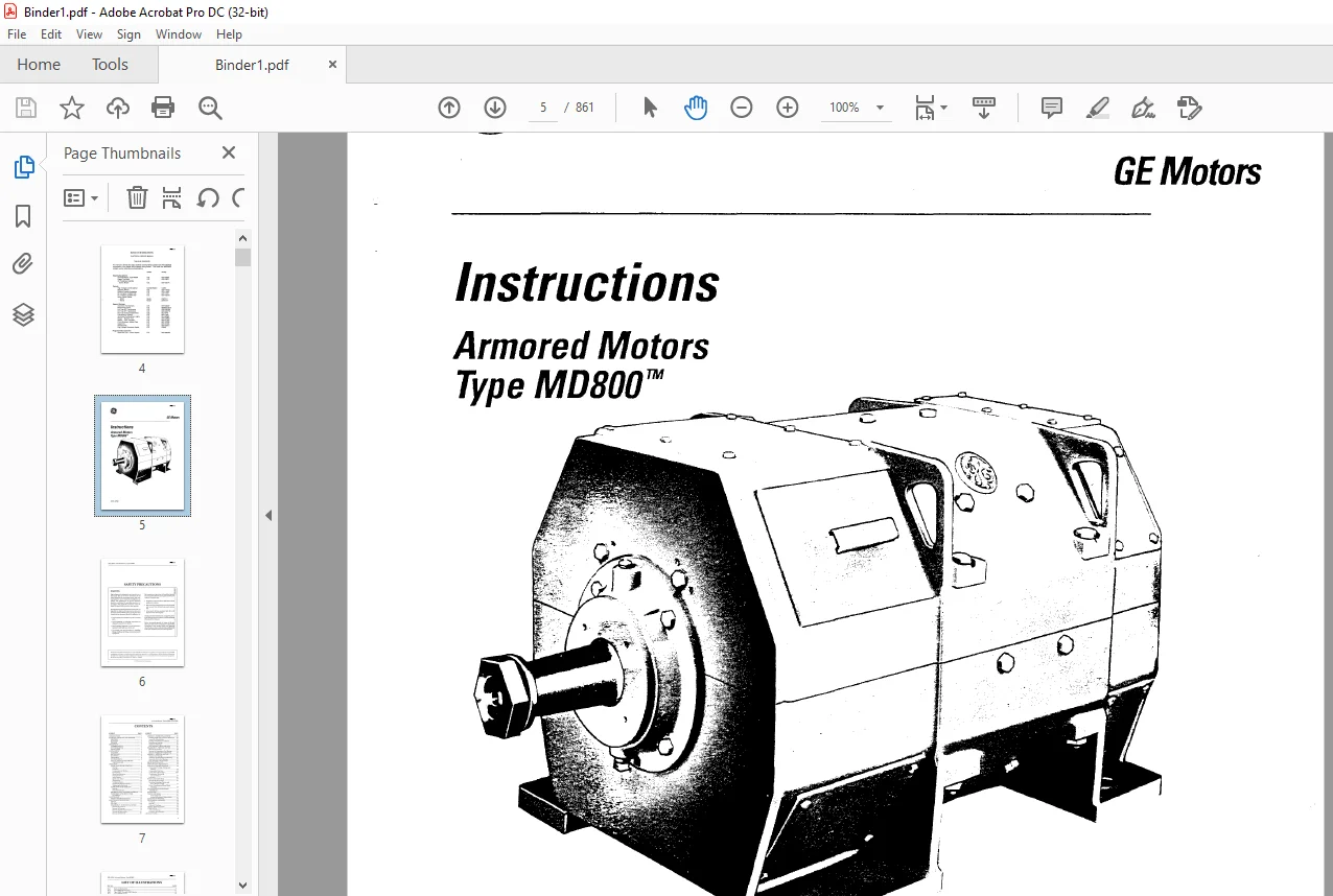
INTRODUCTION
This instruction book covers the MD800 line of Armored Motors.
- High voltage and rotating parts can cause serious or fatal injury. The use of electric machinery, like all other utilization of concentrated power and rotating equipment, can be hazardous. Installation, operation, and maintenance of electric machinery should be performed by qualified personnel.
- Familiarization with NENfA safety standard for construction and guide for selection, installation, and use ofintegralHP motors and generators, National Electrical Code, and sound local practice is recommended. Installation of the machine where hazardous, flammable, or combustible vapors or dusts presenta possibilityofexplosion or fire should be in accordance with the National Electrical Code, Articles 500-503, and consistent with sound local practices.
- These instructions do not purport to cover all details or variation in equipment nor to provide for every possible contingency or hazard to be met in connection with Armored Motors,
- Type MD800, GEH-3258/ installation, operation and maintenance. Should further information be desired or should particular problems arise which are not covered sufficiently for the purchasers’ purposes, the matter should be referred to GE Motors – DM&G.
RECEIVING, HANDUNG
AND STORAGE
RECEIVING
The equipment should be placed under adequate cover immediately upon receipt as packing coverings are not suitable for out-of-doors or unprotected storage. This includes adequate protection from construction dirt, during and after installation. Each shipment should be carefully examined upon arrival. Any damage should be reported promptly to the carrier and to the nearest office of GE Motors.
HANDlING
Motors can be lifted by using hooks or slings in the lifting lugs on the frame. These lugs are designed to safely carry the weight of the whole machine. Blowers should be protected with spreader bars if necessary. Ventilating hoods may have to be removed to clear hooks. Do not lift the machine by the shaft extensions.
IMAGES PREVIEW OF THE MANUAL:
TABLE OF CONTENTS:
CAT BUCYRUS MARION 301-M MINING SHOVEL ELECTRICAL SERVICE MANUAL BI005615 – PDF DOWNLOAD
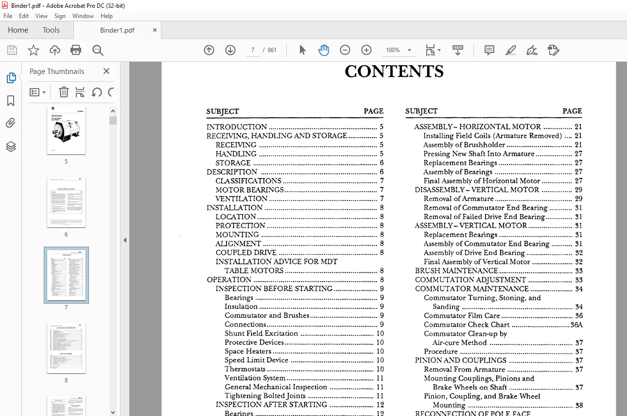
INTRODUCTION 5
RECEMNG, HAJ.’WLING AJ.”lD STORAGE 5
RECEMNG 5
HAJ.”lDLING 5
STORAGE 6
DESCRIPTION 6
CLASSIFICATIONS 7
]\flOTOR BEARINGS 7
VENTILATION 7
INSTALLATION 8
LOCATION 8
PROTECTION 8
]\flOUNTING 8
ALIGNMS”\iT 8
COUPLED DRIVE 8
INSTALLATION ADVICE FOR MDT
TABLE ]\flOTORS 8
OPERATION 8
INSPECTION BEFORE STARTING 9
Bearings 9
Insulation 9
Commutator and Brushes 9
Connections 9
Shunt Field Excitation 10
Protective Devices 10
Space Heaters ; 10
Speed limit Device 10
Thermostats 10
Ventilation System 11
General Mechanical Inspection 11
Tightening BoltedJoints 11
INSPECTION AFTER STARTING 12
Bearings 12
Noise and Vibration 12
BEFORE PUTTING :V!ACHINE IN SERVICE 13
INSPECTION AFTER SHORT TIME
IN SERVICE 13
]\fIAINTENANCE 13
PRODUCTIVE MAD.1ENA.~CE 13
MAINTENAJ.-“‘;CE PROCEDURES 15
REPAIR 15
FAILURE 16
DISASSEMBLY- HORIZONTAL MOTOR 16
Removal ofArmature 16
Removal of Bearings 16
Removal of Shaft From Armature 17
Removal of Brushholder 21
Removal of Field Coils 21
ASSEMBLY- HORIZONTAL MOTOR 21
Installing Field Coils (Armature Removed) 21
Assembly of Brushholder 21
Pressing New Shaft Into Armature 27
Replacement Bearings 27
Assembly of Bearings 27
Final Assembly of Horizontal Motor 27
DISASSEMBLY- VERTICAL MOTOR 29
Removal ofArmature 29
Removal of Commutator End Bearing 31
Removal of Failed Drive End Bearing 31
ASSEMBLY- VERTICAL MOTOR 31
Replacement Bearings 31
Assembly of Commutator End Bearing 31
Assembly of Drive End Bearing 32
Final Assembly of Vertical Motor 32
BRUSH NIAINTENAJ.”\iCE 33
COMMUTATION ADJUSTMENT 33
COMMUTATOR NIAINTENANCE 34
Commutator Turning, Stoning, and
Sanding 34
Commutator Film Care 36
Commutator Check Chart 36A
Commutator Clean-up by
Air-cure Method 37
Procedure 37
PINION AJ.”lD COUPLINGS 37
Removal From Armature 37
Mounting Couplings, Pinions and
Brake Wheels on Shaft 37
Pinion, Coupling, and Brake Wheel
Nlounting 38
RECON”NECTION OF POLE FACE
ASSE:YlBLIES 39
INSULATION 40
TESTING METHODS 41
Visual Inspection 41
Insulation-Resistance Measurement 41
CLEA”.. \iING OF WINDINGS 42
FIELD SERVICE CLEAJ.”lING 42
Dry Dusts 42
Oily Dirt 42
Drying of Windings 43
SERVICE SHOP CLEANING 43
LUBRICATION 43
Armature Bearings 43
Frequency of Lubrication 44
Shaft and Bearing Seal 9
Type l\tID808 Bearing Parts 17
Type MD820 Through l\tID824 Section 18
Type MDP828 Section 19
Type MD808 With Top Half Opened For Removal of Armature 20
Compensating Winding Connections At Frame Split 22
Drive End Brazed Pole Face Connections 23
Commutator End Brazed Pole Face Connections 24
Typical Bolted Pole Face Connection 25
Removal of Inner Race of Bearing With Puller 26
Shaft Removal 28
Pressing in New Shaft MD802 Through MD818 28
Pressing in New Shaft MD820 Through MD828 28
Typical Section View of Bearing Assembly. Types MDV810 Through MDV818 Vertical Motors 29
Type l\tIDV820 Thru MDV824 Section 30
Micrometer Depth Gage Being Used To Measure Pinion Advance 40
l\tIDT Drive End Bearing 45
MDP804 Through MDP808 Motors, Exploded View – Horizontal .49
MDV804 Through MDV808 Motors, Exploded View- Vertical 50
MDP810 Through MDP818 Motors, Exploded View- Horizontal 51
MDV810 Through MDV818 Motors, Exploded View- Vertical 52
l\tIDP820, Exploded View – Horizontal 53
l\tIDP822 Motors, Exploded View – Horizontal 54
l\tIDV820, MDV822 Motors, Exploded View- Vertical 55
Table 12
Typical Weights 5
Speed Limit Device – Maximum Current Ratings 10
Thermostat – ~laximum Current Ratings 10
Bolt Tightening Torque Values – Metallic Parts 11
Bolt Tightening Torque Values – Non-Metallic Parts to Metallic Parts .~ 12
Commutator Condition vs. Recommended Remedy 36
Coupling Hub or Pinion Mounting Data 39
Coating lVlaterial 41
Effect of Temperature on Insulation Resistance 44
Bearing Greases 44
Bearing Lubrication Data 45
Metric Conversion Factors 48
Suggested l\tlaintenance Schedule 14
Grading of Commutation 35
Troubleshooting Guide
Contact us: [email protected]
https://vimeo.com/861621218?share=copy
PLEASE NOTE:
- This is the same manual used by the DEALERSHIPS to SERVICE your vehicle.
- The manual can be all yours – Once payment is complete, you will be taken to the download page from where you can download the manual. All in 2-5 minutes time!!
- Need any other service / repair / parts manual, please feel free to contact us at heydownloadss @gmail.com . We may surprise you with a nice offer
S.M