CAT BUCYRUS RUSTON-BUCYRUS 150-RB EXCAVATOR OPERATION & MAINTENANCE INSTRUCTIONS MANUAL – PDF DOWNLOAD
$28.95
CAT BUCYRUS RUSTON-BUCYRUS 150-RB EXCAVATOR OPERATION & MAINTENANCE INSTRUCTIONS MANUAL – PDF DOWNLOAD
Description
CAT BUCYRUS RUSTON-BUCYRUS 150-RB EXCAVATOR OPERATION & MAINTENANCE INSTRUCTIONS MANUAL – PDF DOWNLOAD
FILE DETAILS:
CAT BUCYRUS RUSTON-BUCYRUS 150-RB EXCAVATOR OPERATION & MAINTENANCE INSTRUCTIONS MANUAL – PDF DOWNLOAD
Language : English
Pages :285
Downloadable : Yes
File Type : PDF
DESCRIPTION:
CAT BUCYRUS RUSTON-BUCYRUS 150-RB EXCAVATOR OPERATION & MAINTENANCE INSTRUCTIONS MANUAL – PDF DOWNLOAD
DESCRIPTION OF OPERATION
General
The electrical machines for each motion of the excavator are a control exciter, ·a main generator and a driving motor. Fig.1 shows the basic electrical scheme, for one motion.
CQntrol :Exciter
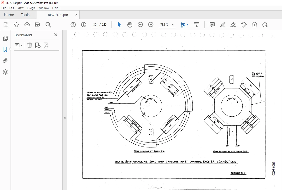
The control exciter is a constant speed D.C. generator, the output from which provides the main excitation for the main generator. It has a field system with four windings referred to as:-
1.Control Field.
2.Self’ Field.
3.Current Field.
4.Voltage Field.
- The. Control Field is excited from a separate supp~ throur,ll a master controller of the reversing type. The polarity and strength of this field are the primary f’actors in determining the output of the control exciter. The Self Field, connected across the armature of the control exciter, assists the control field and is dependent on the output voltage of’ the exciter. The Current Field, connected in the main generate~ armature circuit, opposes the control field.
- An increase in main generator current causes a decrease in control exciter excitation. This reduces the control exciter output to the main generator field. The current field thus limits the current in the main generator armature circuit. The Voltage Field is connected across the armature of the main genera tor and opposes the control f’:i.eld. Initial~, the control exciter a,pplies to the main genera.tor, a slightly boosted field which is corrected by the voltage field as the generator voltage builds up. 1bis allows a f’aster build up of generator voltage.
- It also assists in a more rapid decay of exciter output when the exciter control field is switched of’f’ or reversed.
IMAGES PREVIEW OF THE MANUAL:
TABLE OF CONTENTS:
CAT BUCYRUS RUSTON-BUCYRUS 150-RB EXCAVATOR OPERATION & MAINTENANCE INSTRUCTIONS MANUAL – PDF DOWNLOAD
CONTENTS
LIST OF EQUIPMENT
LIST OF DRAWINGS
DESCRIPTION OF OPERATION
ROTATING ELECTRICAL MACHINES
THE CONTRoL CUBICLE
RESISTANCE FRAMES
BOOM HOIST STARTER
RO’l’.A’l’ING MACHINES
Main M.G. Set pomprising:-
* Drive Motor – 300 h.p. Squirrel Cage Induction
* Hoist/Crowd do~ble armature Generator
•·· Swing Generator:
Constant Voltage Exciter Set comprising:-
• Drive Motor – 22~ h~p.- Sq~irrel Cage Induction
• Constant Voltage Exciter
Control Exciter Set comprising:-
• Drive Motor – 12~ h.p. Squirrel Cage Induction
“‘ Hoist Motion Control Exciter .
Crowd Motion Control Exciter
• Swing Motion Control Exciter
Four work motors:-
·• Hoist Motion d.o. Motor
Crowd Motion d.o. Motor
• Swing Motion d.o. Motors (2)
CONTROL EQUIPMENT
·• Control Cubicle
• Double. T.ier Resistance Frames (3}
• Items marked thus are common for both Shovel and
Dragline Duty.
Main M.G. Set
Drive Motor Connections
Swing Generator Connections
Double .ArmatureGenerator Connections
C.V.E. Set
Drive Motor Connections
Exciter Connections
Control Exciter Set
Drive Motor Connections
Bedplate Connections
Control Exciter Connections
Motors
Shovel Hoist/Dragline Drag &
Dragline Hoist
Shovel Crowd & Swing
Shovel Hoist/Dragline Drag Connections
Shovel Crowd Connections
Dragline Hoist Connections
Swing Connections
Boom Hoist Connections
Section 6
Frame 1 (Double Tier) Connection Dia.gram
Frame 2 (L.H.Double Tier) Connection
Diagram
Frame 3 (R.H. Double Tier) Connection
Diagram
Section 7
Boom Hoist Starter Diagram
General 3/1
Control Exciter 3/1
Generator 3/2
Motor 3/2
Operation of’ Machines in Combination 3/2
Braking 3/3
_) Full Control Scheme 3/3
_) ·.. Fig.1 BASIC FIELD CIRCUIT DIAGRAM
Fig.2 GENERATOR AND MOTOR CHARACTERISTICS
Customer Support: [email protected]
https://vimeo.com/861941249?share=copy
PLEASE NOTE:
- This is the SAME exact manual used by your dealers to fix your vehicle.
- The same can be yours in the next 2-3 mins as you will be directed to the download page immediately after paying for the manual.
- Any queries / doubts regarding your purchase, please feel free to contact [email protected]
S.M