CAT BUCYRUS SCH5000 Hydra-Trac® Hydraulic Track Drill Operator and Maintenance Manual – PDF DOWNLOAD
$28.95
CAT BUCYRUS SCH5000 Hydra-Trac® Hydraulic Track Drill Operator and Maintenance Manual – PDF DOWNLOAD
Description
CAT BUCYRUS SCH5000 Hydra-Trac® Hydraulic Track Drill Operator and Maintenance Manual – PDF DOWNLOAD
FILE DETAILS:
CAT BUCYRUS SCH5000 Hydra-Trac® Hydraulic Track Drill Operator and Maintenance Manual – PDF DOWNLOAD
Language : English
Pages :143
Downloadable : Yes
File Type : PDF
DESCRIPTION:
CAT BUCYRUS SCH5000 Hydra-Trac® Hydraulic Track Drill Operator and Maintenance Manual – PDF DOWNLOAD
General Information
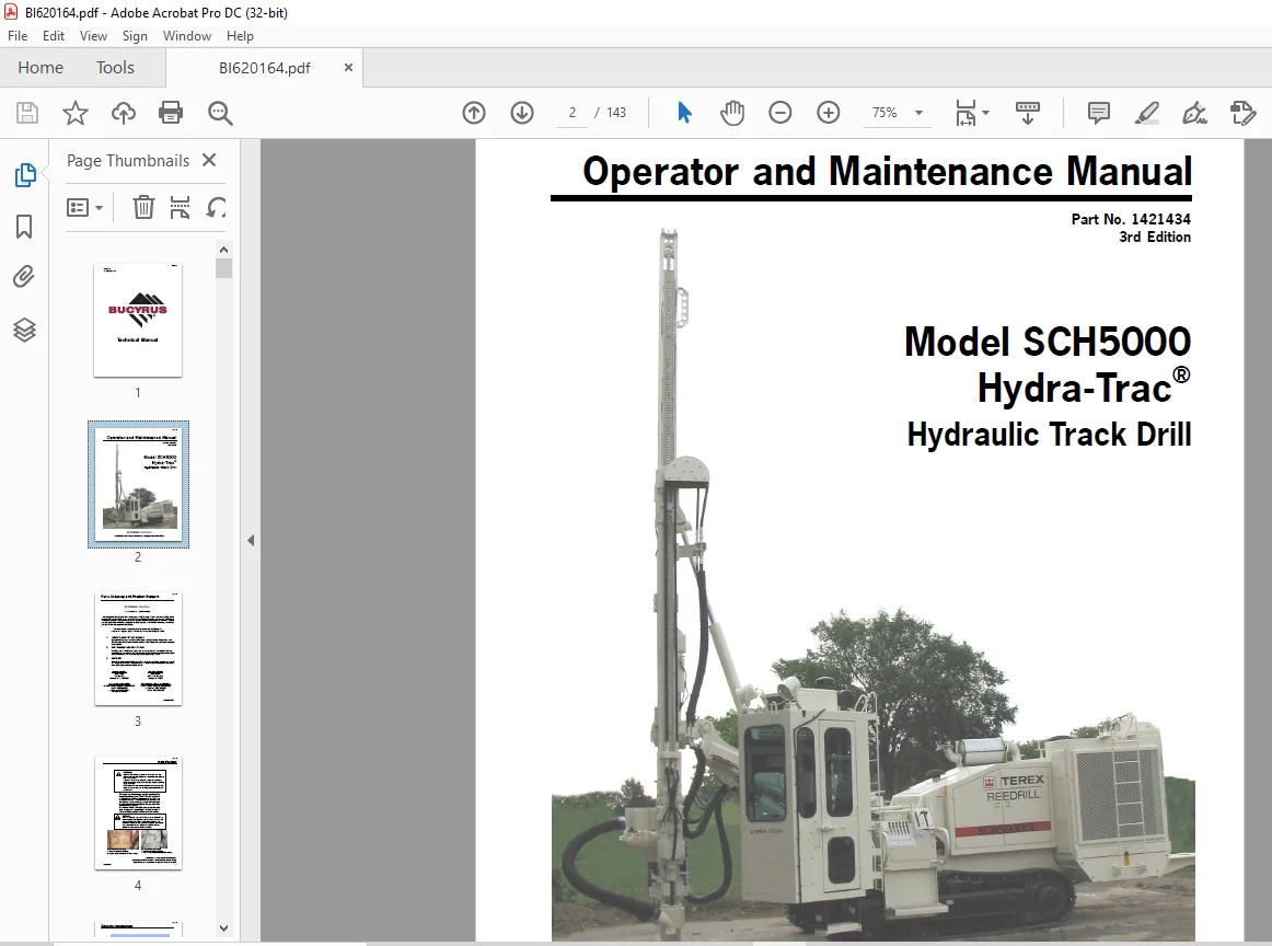
The TEREX Reedrill SCH5000 series Hydra-Trac and HPR5128 (HPR2-C1) drill make an ideal drilling package for a wide range of mining and construction applications. The SCH5000 Hydra-Trac is easy to operate, maneuverable, and efficient. A fully self-contained drill carrier, the Hydra-Trac consists of the following main components:
1. D-4 type track assemblies with 15 inch triple-bar grousers.
2. Prime mover – Caterpillar model C-11 ACERT, Tier 3 electronic diesel engine rated at 325 B.H.P. @
1800RPM.
3. Hydraulic system, consisting of three (3) hydraulic pumps driven by the prime mover thru an elastic
coupling to the pump drive gearbox.
4. Drill/right-hand tram pump – Rexroth A11VLO. Compressor/left-hand tram pump – Rexroth A11VLO.
Drill rotation pump – Vickers PVE-19
5. 400 C.F.M. compressor driven by a piston hydraulic motor provides plenty of blowing air for large
hole sizes.
6. A 12′ chain feed (20′ Model SCH5000CL) powered by a hydraulic piston motor, complete with a
hydraulic powered, scissors type centralizer, an automatic linear rod changer, rack, and hose reel
system.
7. Model HPR5128 (HPR2-C1) hydraulic percussion drill complete with nitrogen charge kit. The HPR5128
Hydra-Drill is a high performance hydraulic rock drill that produces 3 1/2 inch (8.9 cm) and larger
holes in medium to hard rock.
- The SCH5000C/SCH5000CL operator cab is sound suppressive pressurized, with air conditioning. The cab encloses control consoles for tramming, drilling, and positioning, and is mounted on the left side of the carrier.
- The SCH5000 (non-cab machine) is equipped with a drill console mounted on a hydraulically movable arm for safety and comfortable operation. Machines equipped with optional dust collector incorporate an additional pump dedicated for operation of the dust collector fan.
- The heavy duty 3′ extendable telescoping boom is installed on all SCH5000/5000C model machines. The boom has large wear pads and all externally mounted cylinders, which combine for long component life and easy access for service areas. The combination of the telescoping boom and the 12′ feed system provide accurate and fast set-up for all drilling functions. A massive non-extendable boom is provided on SCH5000CL machines.
- This boom system combines with a 20′ feed system that can satisfy all high production demands. The heavy duty construction and low center of gravity make this self contained carrier a highly stable drilling platform. Overlapping track pads and track frame with + 8% oscillation provide positive ground contact when
IMAGES PREVIEW OF THE MANUAL:
TABLE OF CONTENTS:
CAT BUCYRUS SCH5000 Hydra-Trac® Hydraulic Track Drill Operator and Maintenance Manual – PDF DOWNLOAD
SCH5000 Operator 3rd Ed.pdf..............................................  0
	Parts Ordering & Product Support.....................................  0
	Introduction.........................................................  3
		General Information..............................................  5
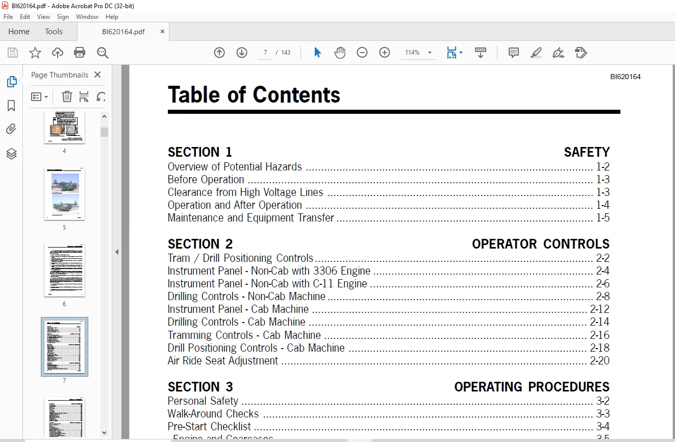
		Table of Contents................................................  7
	Section 1 SAFETY..................................................... 10
		Overview of Potential Hazards.................................... 11
		Safety Instructions.............................................. 12
	Section 2 Operator Controls.......................................... 16
		Tram/Drill Positioning Controls.................................. 17
		Instrument Panel - Non-Cab with 3306 Engine...................... 19
		Instrument Panel - Non-Cab with C-10/11 Engine................... 21
		Drilling Controls - Non-Cab Machine.............................. 23
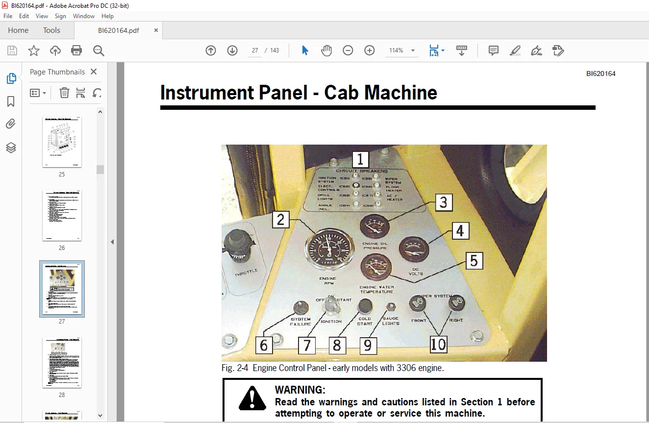
		Instrument Panel - Cab Machine................................... 27
		Drilling Controls - Cab Machine.................................. 29
		Tramming Controls - Cab Machine.................................. 31
		Drill Positioning Controls - Cab Machine......................... 33
		Air Ride Seat.................................................... 35
	Section 3 Operating Procedures....................................... 36
		Personal Safety.................................................. 37
		Walk-Around Checks............................................... 38
		Pre-Start Checklist.............................................. 39
			Engine and Gearcases......................................... 40
			Pneumatic System............................................. 40
			Feed Table Pivot Pin......................................... 41
			Boom, Feed and Drill......................................... 42
			Drill Accumulators........................................... 42
		Daily Maintenance................................................ 43
		Mounting & Dismounting Machine................................... 44
		Start-Up Procedure............................................... 45
			Cold Weather Starting........................................ 46
		Tramming-Preliminary Checks and Warnings......................... 47
		Tramming from Operator's Cab..................................... 48
		Tramming from Tram Station....................................... 49
		Shutdown Procedure............................................... 51
	 Section 4 Drilling Procedures....................................... 54
		Loading Drill Steel.............................................. 55
		Drill Positioning Procedure...................................... 57
		Drilling Procedure............................................... 63
			Collaring The Hole........................................... 63
			Collaring Circuit............................................ 66
			Normal Drilling.............................................. 66
		Drilling Practices............................................... 67
			Collaring.................................................... 67
			Hole Deviation............................................... 67
			Feed Pressure................................................ 67
			Drill Pressures.............................................. 67
			Adjusting Drill Pressure and Monitoring the Machine.......... 67
			Plugged Bit and Stuck Drill Steel............................ 67
		Anti-Jam System (optional)....................................... 69
		Reverse Percussion (optional).................................... 71
		Adding and Removing Drill Steel.................................. 73
			Adding Drill Steel........................................... 73
			Removing Drill Steel......................................... 74
		HPR2 Drill Shank Replacement..................................... 76
		Indexing the Swing Cylinder...................................... 77
	Section 5 Preventive Maintenance..................................... 80
		Hydraulic Oils for Percussion Drills............................. 81
		Lubrication and Inspection....................................... 82
			Engine Oil................................................... 82
		Bolt Maintenance................................................. 83
		Bolt Torque Specifications....................................... 84
		Preventive Maintenance Chart..................................... 85
		SCH5000 Grease Points............................................ 87
			Drill & Centralizer Grease Points............................ 89
			Feed & Feed Drive Grease Points.............................. 90
			Lower Rod Rack & Rod Wrench Grease Points.................... 91
			Rod Rack Driveline Grease Points............................. 92
			Upper Rod Rack & Hose Reel Grease Points..................... 93
			Feed Table Grease Points..................................... 94
			Positioner (12 Ft. Feed) Grease Points....................... 95
			Positioner (20 Ft. Feed) Grease Points....................... 96
			Boom Assembly Grease Points.................................. 97
			Drill Console Boom (non-cab) Grease Points................... 98
			Cab Mounting Grease Points................................... 99
			Track Assembly Grease Points.................................100
			20 Ft. Feed Headrest Grease Points...........................101
			C-10 & C11 Engine Fan Drive Grease Point.....................101
		Maintenance Record...............................................102
	Section 6 Drill Maintenance..........................................108
		Charging the Accumulators........................................109
			Requirements.................................................109
			Procedure....................................................110
		Checking the Accumulator Charge Pressure.........................111
		Accumulator Charge Kit...........................................113
		Lubrication......................................................114
			Grease Lubrication with a Hand Grease Gun....................114
			Automatic Lubrication........................................114
		Automatic Grease Lubricator (optional)...........................115
	Section 7 Dust Control...............................................118
		WARNING: HEALTH HAZARD...........................................118
		Dust Collector Assembly..........................................119
		Function of Dust Collector.......................................120
		Detailed Function of Components..................................120
		Dust Collector Setup.............................................121
			Initial Start-up and Tuning..................................121
			Dust Collector Valve - Adjustment (non-electronic engine)....122
			Dust Collector Valve - Adjustment (electronic engine)........123
			Air Pressure Regulator - Adjustment..........................124
			Timer - Adjustment...........................................125
		Filter Elements..................................................127
		Dust Collector Efficiency........................................127
		Operational Variables............................................128
		Fine Tuning......................................................128
		Manometer Setup Instructions.....................................129
		Timer Installation...............................................131
		Control Circuit..................................................132
		Fan Removal and Installation.....................................133
		Troubleshooting Hints............................................134
		Detergent System.................................................136
			Description..................................................136
			Operation....................................................136
		Filling The Tank.................................................138
		Servicing the "Y" Strainer.......................................138
		Detergent System Freeze Protection...............................138
		Detergent System Piping..........................................139
	Section 8 Glossary...................................................140
Customer Support: [email protected]
https://vimeo.com/864402529?share=copy
PLEASE NOTE:
- This is the SAME manual used by the dealers to troubleshoot any faults in your vehicle. This can be yours in 2 minutes after the payment is made.
- Contact us at [email protected] should you have any queries before your purchase or that you need any other service / repair / parts operators manual.
S.M