CAT Bucyrus Shield Support 1300/3100 Operation Manual PDF Download
$26.95
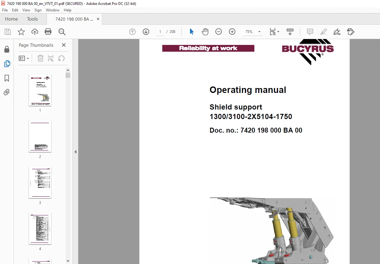
CAT Bucyrus Shield support 1300/3100-2X5104-1750 Operating Manual – PDF DOWNLOAD
Doc. no.: 7420 198 000 BA 00
Description
CAT Bucyrus Shield support 1300/3100-2X5104-1750 Operating Manual – PDF DOWNLOAD
FILE DETAILS:
CAT Bucyrus Shield support 1300/3100-2X5104-1750 Operating Manual – PDF DOWNLOAD
Language : English
Pages :208
Downloadable : Yes
File Type : PDF
IMAGES PREVIEW OF THE MANUAL:
TABLE OF CONTENTS:
CAT Bucyrus Shield support 1300/3100-2X5104-1750 Operating Manual – PDF DOWNLOAD
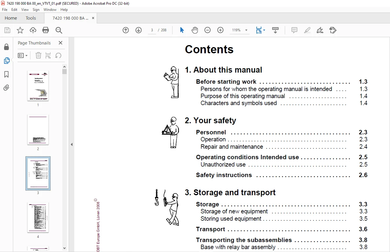
Contents
1 About this manual
Before starting work 1 3
Persons for whom the operating manual is intended 1 3
Purpose of this operating manual 1 4
Characters and symbols used 1 4
2 Your safety
Personnel 2 3
Operation 2 3
Repair and maintenance 2 4
Operating conditions Intended use 2 5
Unauthorized use 2 5
Safety instructions 2 6
3 Storage and transport
Storage 3 3
Storage of new equipment 3 3
Storing used equipment 3 5
Transport 3 6
Transporting the subassemblies 3 8
Base with relay bar assembly 3 8
Caving shield 3 9
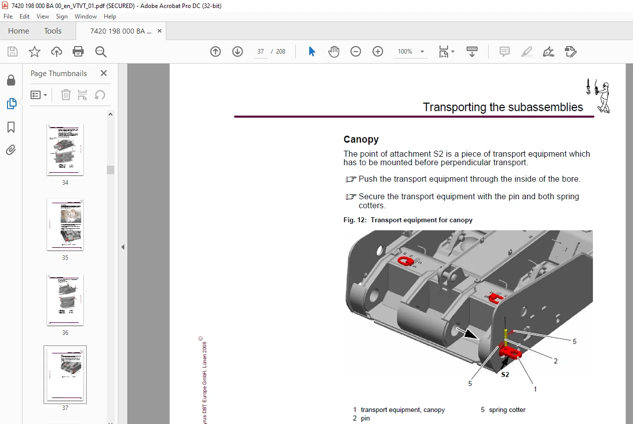
Canopy 3 11
Flipper 3 15
Prop 3 15
Transporting the shield support 3 16
Transport safety device 3 18
4 Installation
Points to observe prior to installation 4 3
Who is allowed to carry out installation? 4 3
Which tools are required for installation? 4 3
Installation instructions 4 4
Installation of the shield support 4 5
Installing the assembly consoles 4 7
Preparing the caving shield for installation 4 9
Mounting the caving shield 4 10
Mounting the props 4 11
Mounting the prop control valves 4 13
Preparing the canopy for installation 4 14
Mounting the flipper on the canopy 4 16
Mounting the dual check valve on the flipper cylinder 4 19
Mounting the flipper on the shield 4 20
Mounting the stabilizing cylinder 4 22
Component overview 4 23
Pilot-operated check valve for shifting ram 4 24
Mounting the double filters 4 24
Mounting the hose holder 4 25
Mounting the electrohydraulic control unit 4 25
Mounting the solenoid driver module 4 27
Mounting the water valve 4 28
Mounting the supply block 4 29
Mounting the PMC®-R with bracket 4 29
Mounting the protection covers for the prop control valves 4 31
Mounting the rubber covering 4 32
Mounting the lamp 4 33
Mounting the additional devices 4 34
Prop protection 4 34
Installing the hoses of the installation assembly
groups that have already been mounted 4 35
Mounting the rock burst valve 4 36
Setting up the hose connections for additional
installation subassemblies 4 36
Before you release the shield for installation 4 37
Mounting branch lines 4 38
How to install the shield units 4 42
Pressure equalization of the electronic control system 4 43
Supply connections 4 44
Establish a link between the connections 4 47
Requirements for the face hydraulic system 4 48
Commissioning 4 49
To be observed prior to start-up 4 49
How to put the support into operation 4 51
Corrosion protection of hydraulic components 4 51
5 Operation
Requirements 5 3
Operating conditions 5 3
Safety requirements 5 6
Operation of the shield support 5 9
Work safety 5 14
Operation of the shield hydraulics 5 15
Arrangement of hydraulic components on the support 5 15
Functions of the HP ball valves 5 17
Shield hydraulics 5 18
Brackets and accessories 5 28
Shield components 5 30
Retracting or extending side seal 5 40
Plug with pressure relief 5 41
Operation of the double backflush filter 5 43
Repair and emergency operation 5 44
Operation and functions of the electrohydraulic
control unit 5 45
Functions of the water valve unit 5 48
Maintenance 5 49
Special measures 5 49
Daily maintenance 5 50
Weekly maintenance 5 50
Every six months 5 51
Assessment of damage according to schedule 5 51
Troubleshooting 5 52
Instructions for troubleshooting 5 52
Fault localization 5 52
3/2-way or pilot valve 5 55
Piloted check valves 5 55
Internal by-pass in props 5 56
Pressure relief valve defective 5 56
Defective or blocked filter 5 56
6 Technical data
Technical description 6 3
Main subassemblies 6 4
Main dimensions 6 5
Base with lemniscatic links and relay bar assembly 6 6
Canopy 6 10
Prop head with peg 6 11
Flipper 6 12
Side seal 6 13
Caving shield 6 16
Additional device 6 17
Technical data, steel structure 6 18
Bucyrus DBT Europe GmbH, Lünen 2008E
Contents
Shield support 1300/3100-2X5104-1750
Hydraulic system 6 19
Shield hydraulics 6 19
Two-stage telescopic prop 6 26
Hydraulic cylinders 6 28
Construction 6 28
Stabilizing cylinder 6 29
Shifting ram 6 29
Lifting cylinder 6 30
Flipper cylinder 6 30
Seal cylinders 6 31
Pusher cylinder 6 31
Technical data, hydraulic cylinder 6 32
Pressure relief valves 6 34
Shield control system 6 36
Electrohydraulic control unit 6 36
PMC®-R control unit 6 37
Angles of inclination of the canopy 6 38
Permissible media 6 39
Hydraulic fluids 6 39
Quality of the process water 6 41
Lubricating greases and pastes 6 43
Tightening torques 6 45
Screws with ISO metric thread 6 45
7 For your information
Service addresses 7 3
Europe 7 3
North America, Canada, South America 7 4
Australia 7 4
Africa 7 4
Asia 7 5
Identification of the shield 7 6
Type plate 7 6
Shield number 7 7
Standards and guidelines 7 8
Referenced national standards and guidelines 7 8
Referenced European standards and directives 7 8
Customer Support: [email protected]
https://vimeo.com/896149190?share=copy
S.M