Trusted Business
Verified & Licensed
Virus Free Files
100% Safe Downloads
Secure Payment
SSL Protected
Instant Delivery
Available Immediately
Repair Manual for Cat Bucyrus SKF-98 Infinity Drill SN TRX68SKFPDN9K0008
$32.95
Cat Bucyrus SKF-98 Infinity Blasthole Drill Service Manual SN TRX68SKFPDN9K0008 – PDF DOWNLOAD
Instant PDF Download
Available immediately
Save to Your Device
Download & keep forever
Antivirus Scanned
100% virus-free
Trusted Worldwide
175,000+ customers
Description
Cat Bucyrus SKF-98 Infinity Blasthole Drill Service Manual SN TRX68SKFPDN9K0008 – PDF DOWNLOAD
FILE DETAILS:
Cat Bucyrus SKF-98 Infinity Blasthole Drill Service Manual SN TRX68SKFPDN9K0008 – PDF DOWNLOAD
Language : English
Pages : 717
Downloadable : Yes
File Type : PDF
IMAGES PREVIEW OF THE MANUAL:
DESCRIPTION:
Cat Bucyrus SKF-98 Infinity Blasthole Drill Service Manual SN TRX68SKFPDN9K0008 – PDF DOWNLOAD
Safety Information:
- This manual is furnished with your Infinity Series rotary blasthole drill to aid you in performing
the necessary service work to maintain your drill in good operating condition. - This manual contains repair and adjustment information for all major operating systems on the
machine. In some cases such as hydraulic pumps and motors it is better to replace the unit with a
new or rebuilt unit than to perform major repairs. Should further information be desired or should
particular problems arise which are not covered sufficiently in this manual, the matter should be
referred to manufacturer. - The descriptions and specifications contained in this manual were in effect at the time of printing.
The right is reserved to make changes at any time without notice and without obligation. - It is YOUR responsibility to understand and follow manufacturer’s instructions on machine operation
and service, and to observe pertinent safety precautions, laws and regulations. Failure to read and
understand this manual and all safety, capacity and instruction placards on the machine before
operating the unit, constitutes a misuse of the machine. - It is your responsibility to know the
manufacturer’s specific requirements, government regulations, required precautions and any work
hazards which may exist. You must make these known to all personnel working with the equipment or
in the area, so that all may take the necessary and required safety precautions. Keep all children,
visitors, and untrained personnel away from the equipment. - It is also your responsibility to
operate your equipment with skill, good judgment, and caution. Following recognised safety
procedures will help you avoid accidents. Failure to heed these instructions can result in property
damage, serious injury or death.
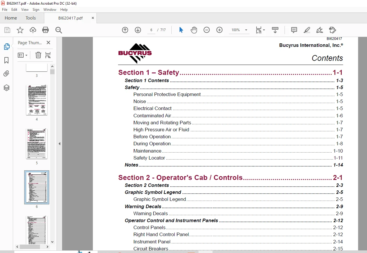
TABLE OF CONTENTS:
Cat Bucyrus SKF-98 Infinity Blasthole Drill Service Manual SN TRX68SKFPDN9K0008 – PDF DOWNLOAD
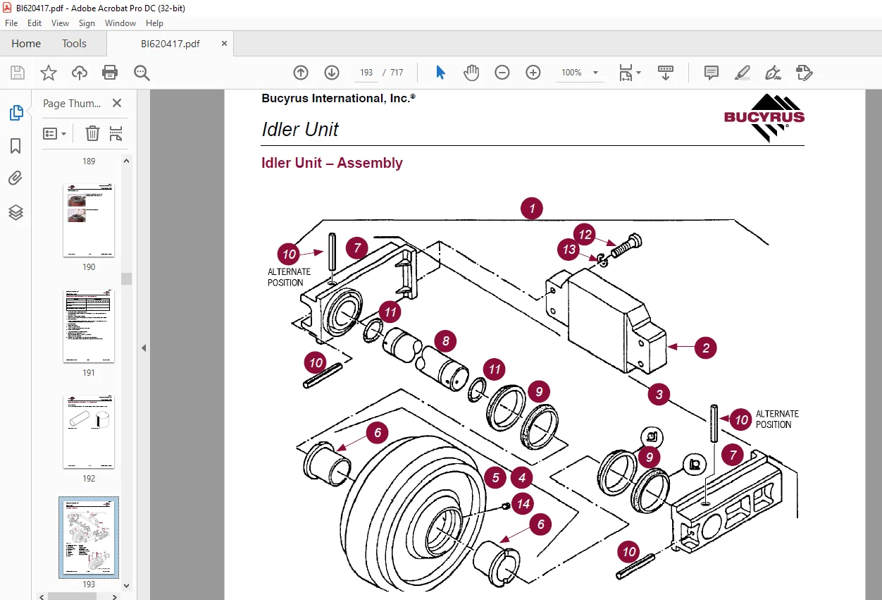
SKF-98~K0008.PDF................................................................................  0
	SKF-98 Infinity Blasthole Drill Serial No.TRX68SKFPDN9K0008 Service Manual..................  2
		Parts Ordering and Product Support......................................................  4
		Safety Information......................................................................  5
		Contents................................................................................  6
			Page Int-5 .........................................................................  6
			Page Int-6 .........................................................................  7
			Page Int-7 .........................................................................  8
			Page Int-8 .........................................................................  9
			Page Int-9 ......................................................................... 10
			Page Int-10......................................................................... 11
			Page Int-11 ........................................................................ 12
			Page Int-12 ........................................................................ 13
			Page Int-13......................................................................... 14
			Page Int-14......................................................................... 15
			Page Int-15......................................................................... 16
			Page Int-16......................................................................... 17
			Page Int-17 ........................................................................ 18
			Page Int-18......................................................................... 19
		General Locator......................................................................... 20
			General Locator..................................................................... 20
		Notes................................................................................... 23
		Section 1 Safety........................................................................ 24
			Contents............................................................................ 26
				Page 1-3 ....................................................................... 26
			Safety.............................................................................. 28
				Personal	Protective	Equipment................................................... 28
				Noise........................................................................... 28
				Electrical	Contact.............................................................. 28
				Contaminated Air ............................................................... 29
				Moving	and	Rotating	Parts....................................................... 30
				High	Pressure	Air	or	Fluid...................................................... 30
				Before Operation................................................................ 30
				During	Operation................................................................ 31
				Maintenance..................................................................... 33
				Safety	Locator.................................................................. 34
			Notes............................................................................... 37
		Section 2 Operators Cab / Controls...................................................... 38
			Contents............................................................................ 40
				Page 2-3 ....................................................................... 40
			Graphic Symbol Legend............................................................... 42
				Graphic	Symbol	Legend........................................................... 42
			Warning Decals...................................................................... 46
				Warning	Decals.................................................................. 46
			Operator Control and Instrument Panels.............................................. 49
				Control Panels.................................................................. 49
				Right	Hand	Control	Panel........................................................ 49
				Instrument Panel................................................................ 51
				Circuit Breakers................................................................ 52
				Light	Switches.................................................................. 52
				System	Pressure	Gauge	Panel..................................................... 53
				Left	Hand	Control	Panels........................................................ 55
				Cab Foot Controls............................................................... 59
				Thread	Grease	Switch............................................................ 59
				Pipe	Safety	Arm	Override	Switch................................................. 59
			Machine Stability................................................................... 60
				Tramming	Procedure	for	SK	Series	Drills......................................... 60
				Track Adjustments............................................................... 60
				New Machine Procedure .......................................................... 61
				General	Maintenance	Checks	While	Tramming....................................... 61
				Roller	Locations................................................................ 62
				Temperature	and	Condition	Record	Chart	for	Walking.............................. 63
				Propelling	the	Machine.......................................................... 64
				SKF	Transient	Stability	Limits.................................................. 67
			Cab Heater.......................................................................... 68
				Cab	Heater	Fault	Isolation...................................................... 68
			Air Conditioner..................................................................... 69
				T7	Series	Split	System	Air	Conditioning	Manual.................................. 69
				Section		1.0	Technical	Data	and	Control	Settings................................ 70
				Section	2.0	Installation	and	Commissioning...................................... 72
				Section	3.0	Routine	Maintenance	Procedures...................................... 78
				Section	4.0	Fault	Diagnosis..................................................... 79
				Section		5.0	Reference	Drawings	................................................ 88
			Notes............................................................................... 93
		Section 3 Main Frame / Crawlers......................................................... 94
			Contents............................................................................ 96
				Page 3-3........................................................................ 96
				Page 3-4........................................................................ 97
			Main Frame Repair - General......................................................... 98
				Main Frame Repair............................................................... 98
			Weld Inspection Schedule............................................................ 99
				Main Frame...................................................................... 99
			Levelling Jacks.....................................................................100
				Levelling	Jack	Cylinder.........................................................100
				Levelling	Jacks.................................................................101
				Limit	Switch....................................................................101
				Levelling	Jack	Cylinders........................................................101
			Mast Elevating Cylinders............................................................102
				Mast	Elevating	Cylinders........................................................102
				Internal	Counterbalance	Valve...................................................103
			Crawler Assembly....................................................................105
				Crawler	Assembly................................................................105
				Parts List......................................................................106
				Crawler Component Repair........................................................106
			Tramming............................................................................107
				Maintenance Checks	for	Tramming	for	SK	Series	Drills............................107
				Track	Adjustments...............................................................107
				New Machine Procedure...........................................................108
					General	Maintenance	Checks	While	Tramming......................................108
				Roller Locations................................................................109
				Temperature	and	Condition	Record	Chart	for	Walking..............................110
			Metric Bolt Torque Specifcations....................................................111
				Metric	Bolt	Torque	Specification................................................111
			Track Tension Adjustment............................................................112
				Before	Operating	the	Machine:...................................................112
				General Maintenance.............................................................112
				Track	Assembly..................................................................113
				Idler Unit Description..........................................................114
				Hydraulic Tensioner.............................................................115
				Repair..........................................................................115
				Nitrogen	Tensioner..............................................................116
				Nitrogen	Tensioner	–	 Filling	Instructions......................................117
				Nitrogen	Tensioner	–	Pressure	Check.............................................118
				Nitrogen	Tensioner	–	Pressure	Release...........................................118
			Hydraulic Tensioner.................................................................119
				Hydraulic	Tensioner	Assembly....................................................119
				Repair..........................................................................119
			Track Chain.........................................................................120
				Track	Chain	–	Separate..........................................................120
				Track	Chain	Repair..............................................................121
			Track Shoes Installation............................................................123
				Track	Link	Position.............................................................123
				Track	Shoe	–	Mounting	to	Track	Chain............................................123
			Track Shoe Bolt Torque (Direct Torque Method).......................................125
				Bolt	Torque	KN111...............................................................125
			Track Shoe Bolt Torque (Torque Turn Method).........................................126
				Bolt	Torque	KN111...............................................................126
			Track Chain and Shoe Installation...................................................127
				Track	Chain	with	Shoes..........................................................127
				Track	Chain	and	Shoe	–	Assembly	and	Installation................................127
			Final Drive Unit....................................................................129
				General Description.............................................................129
				Removal	from	Track	Frame........................................................130
				Installation	into	Track	Frame...................................................131
				Final	Drive	Maintenance.........................................................132
				Final	Drive	Oil.................................................................133
				Final	Drive	Assembly............................................................135
				Parking	Brake	–	Description.....................................................136
				Final Drive –	Disconnect and Parking Brake......................................137
				Towing	Procedure	–	Gear	Drive	Disconnect........................................137
				Parking	Brake	–	Description.....................................................138
				Parking	Brake	–	Removal	and	Installation........................................138
				Repair	Manual	Final	Drive	Model	F100	–	General	Information......................139
				Repair	Manual	Final	Drive	Model	F100	–	Safety	Instructions......................144
				Repair	Manual	Final	Drive	Model	F100	–	General	Specification....................148
					Disassembly	and	Assembly	Operations............................................157
				Repair	Manual	Final	Drive	Model	F100	–	Troubleshooting..........................191
				Repair	Manual	Final	Drive	Model	F100	–	Special	Tools............................192
			Idler Unit..........................................................................193
				Idler	Unit	–	Assembly...........................................................193
				Idler	Unit	–	Removal............................................................196
			Track and Support Rollers...........................................................198
				Track	Roller	Assembly...........................................................198
				Track	Roller	–	Removal	and	Disassembly..........................................199
				Support	Roller	–	Removal	and	Disassembly........................................199
				Track	and	Support	Roller	–	Assembly.............................................200
				Track	and	Support	Roller	–	Test	and	Install.....................................201
			Track and Sprocket Inspection.......................................................203
				Track	Inspection	and	Wear	Limit	Guide...........................................203
				Sprocket	Wear	Patterns..........................................................208
			Auxiliary Crane.....................................................................214
				Hydraulic	Crane	–	Rear	Deck	Crane	Palfinge	PC1300...............................214
				Rear	Deck	Crane	Palfinge	PC1300	Service	Information.............................215
				Maintenance Chart...............................................................216
				Lubrication.....................................................................218
				Hydraulic Fluids................................................................221
				Cleaning	Agents	and	Equipment...................................................223
				Repairing	Paint	Damage..........................................................224
				Removal	From	Service	and	Disposal...............................................224
			Notes...............................................................................225
		Section 4 Engine / Drive Train / Compressor.............................................226
			Contents............................................................................228
				Page 4-3........................................................................228
				Page 4-4........................................................................229
			Power Group Locator.................................................................230
				Power Group Locator.............................................................230
			Test Point Locator..................................................................231
				Test Point Locator..............................................................231
			Cummins Engine......................................................................233
				Cummins Engine..................................................................233
				Oil Reserve Systems.............................................................234
				LED Monitor Readings............................................................235
				Adjustment of Running Oil Level.................................................235
				Wiring Diagram – Oil Reserve Basic Circuit......................................236
				Oil Pressure Switch.............................................................236
				Oil Reserve System..............................................................236
				Troubleshooting.................................................................237
				Maintenance.....................................................................238
			Engine and Compressor Air Cleaners..................................................239
				Engine and Compressor Air Cleaner Service Assembly..............................239
				Engine and Compressor Air Cleaner Service.......................................240
			Flexible Drive Coupling.............................................................243
				Flexible Drive Coupling Service.................................................243
			Pump Drive..........................................................................245
				Pump Drive Assembly – Removal and Replacement...................................245
				Pump Drive Gearbox..............................................................246
				Pump Drive Gearbox – Repair.....................................................246
			Hydraulic Pumps.....................................................................248
				Hydraulic Pumps.................................................................248
				Hydraulic Pumps – Removal and Replacement.......................................250
			Compressor Installation.............................................................251
				1700cfm / 100psi Compressor.....................................................251
				Safety..........................................................................252
				Compressor Installation.........................................................255
				Compressor Drive Coupling.......................................................256
				Compressor Alignment............................................................257
				Mounting	Instructions	for	Arcusaflex	Flywheel	Couplings.........................258
				Taper-Loc	Bushing	Installation	–	Model	AC-T5.SN.	F2.	V1.	3535...................259
			Compressor Shaft Seal...............................................................260
				Compressor Shaft Seal...........................................................260
			Low Pressure Compressor.............................................................262
				Description.....................................................................262
				Compressed Air Functions........................................................262
				Compressor Inlet Valve Control System...........................................266
				Inlet Valve.....................................................................267
				Compressor Regulation...........................................................269
				Relieving Regulators............................................................270
				Reducing Regulators.............................................................272
				System Blowdown Valve ..........................................................274
				Running Blowdown Valve..........................................................275
				Running Blowdown Maintenance....................................................276
				Compressor Air and Oil Circuits – 1700cfm @ 100psi..............................277
				Operation.......................................................................280
				Compressor Air Circuit Parts List...............................................282
				Compressor Air Circuit Legend...................................................282
				Compressor Control Set-up Vented Poppet Inlet – Shutdown........................283
				Compressor	Control	Set-up	Vented	Poppet	Inlet	–	Initial	Start-up	Below	50psi....284
				Compressor	Control	Set-up	Vented	Poppet	Inlet	–	Intial	Start-up	Above	50psi.....285
				Compressor Control Set-up Vented Poppet Inlet – Run Unloaded....................286
				Compressor Control Set-up Vented Poppet Inlet – Drilling........................287
			Compressor Maintenance..............................................................288
				General Maintenance.............................................................288
				Discharge Check Valve...........................................................290
				Compressor Receiver Tank Assembly...............................................291
				Separator Elements..............................................................292
				Scavenge Line...................................................................293
				Compressor Discharge Temperature Gauge, Switch and Sender.......................295
				Minimum Pressure Valve..........................................................296
				Minimum Pressure / Check Valve Maintenance......................................296
				Thermal Bypass Valve............................................................297
				Thermal Bypass Valve Maintenance................................................298
				Compressor Fluid Filter.........................................................300
				Changing Filter Elements........................................................301
				Oil stop valve..................................................................302
				Troubleshooting.................................................................303
			Coolers.............................................................................305
				Hydraulic Oil / Radiator Cooler Assembly........................................305
				Compressor Oil Cooler...........................................................306
				Fan speed.......................................................................306
				Engine Cooler / Radiator........................................................307
			Aluminium Tube Air to Oil Cooler....................................................308
				Aluminium Tube Air to Oil Cooler – standard Parts...............................308
				Removal and Replacement.........................................................309
				Oil Cooler – Internal Cleaning..................................................311
			Radiator Cooler.....................................................................313
				Typical Radiator Core – standard Parts..........................................313
				Cleaning........................................................................314
				Tube Removal....................................................................314
				Seal Installation...............................................................315
				Tube Installation...............................................................316
			Notes...............................................................................318
		Section 5 Dust Control System...........................................................320
			Contents............................................................................322
				Page 5-3........................................................................322
				Page 5-4 .......................................................................323
			Dust Control System.................................................................324
				Dust Control Systems............................................................324
			Water Injection.....................................................................326
				Basic	Specification.............................................................326
				Technical Data..................................................................326
				Initial Start-up................................................................328
				Fan Speed Adjustment............................................................328
				Direction of Fan Rotation.......................................................329
				Compressed Air Supply...........................................................330
				Air	Regulator	/	Filter..........................................................330
				Electric	Timer..................................................................331
				Compressed Air Supply...........................................................332
				Filter Maintenance..............................................................332
				Routine Maintenance.............................................................333
				Troubleshooting	Guide...........................................................334
				Water	Injection	Pump	Assembly...................................................335
				Pump	Specification..............................................................336
				Torque Requirements.............................................................336
				Servicing	Instructions..........................................................336
				Servicing	the	Plunger	Packings..................................................336
				Reassembling	Plunger	Packings...................................................337
				Servicing	the	Pump	Valves.......................................................337
				Reassembling	Valve	Parts........................................................337
				Servicing	the	Crankshaft........................................................338
				Servicing	the	Crossheads........................................................338
				Water	Tanks.....................................................................339
				Water	Injection	Relief	Valve....................................................340
				Water Injection Control.........................................................341
				Water Injection Basic Circuit...................................................343
			Water Pump..........................................................................344
				Replacing	Piston	Cup	Seals......................................................344
				Replacing	Suction	and	Discharge	Valves..........................................345
				Replacing	Power	End	Bearings....................................................346
				Servicing	the	Wrist	Pin	Bearings................................................347
				Fastener Torque Requirements....................................................347
				Recommended	Lubricants..........................................................348
				Water Pump Motor Repair.........................................................348
				Water	Injection	Hydraulic	Control	Valve	Repair..................................348
				Water	Pump	Drive	Coupling.......................................................348
				Level	and	Flow	Transducer.......................................................348
			Hydraulic Motor.....................................................................349
				Hydraulic Motor Repair Information..............................................349
				Disassembly.....................................................................350
				Reassembly......................................................................352
				Wheel Motor.....................................................................354
				Wheel Motor with Guard..........................................................354
				Pump Identifcation..............................................................355
			Notes...............................................................................356
		Section 6 Mast / Rotary Drive / Pipe Rack...............................................358
			Contents............................................................................360
				Page 6-3........................................................................360
				Page 6-4  ......................................................................361
			Mast Weldment.......................................................................362
				Mast Repair.....................................................................362
			Weld Inspection Schedule............................................................363
				Mast Inspection.................................................................363
			Mast Assembly and Installation......................................................364
				Mast	Assembly...................................................................364
				Mast Pivot Caps.................................................................365
				Mast	Elevate	Cylinders..........................................................366
				Angle	Drilling..................................................................366
				Mast / Drill Without Mast.......................................................367
				Mast / Drill Without Mast.......................................................368
				Raising	the	Mast................................................................368
			Hoist / Pulldown Cylinder...........................................................370
				Hoist / Pulldown Cylinder.......................................................370
				Feed	Cylinder	Service...........................................................371
				Feed Cylinder – Removal.........................................................372
				Installation....................................................................373
				General Information.............................................................374
				Hoist / Pulldown Cable Adjustment...............................................375
				Hoist	/	Pulldown	Cable	Replacement..............................................376
				Wire Rope.......................................................................377
			Rotary Drive Gearbox................................................................378
				Alignment	Procedure.............................................................378
				Rotary	Drive	Assembly...........................................................379
				Rotary Drive – Removal from Mast................................................380
				Rotary Drive – Installation.....................................................380
				Single	Motor	Rotary	Drive	Gearbox...............................................381
				Air	Swivel	(Dual	Seal	Style)....................................................382
				Service.........................................................................382
				Rotary Drive Motor – Repair.....................................................383
				Top	Mast	Drive	Transmission	TM2132-4	Manual.....................................384
				Preface.........................................................................385
				General	Working	Instructions....................................................386
				Work	Safety.....................................................................387
				Symbol	Explanation..............................................................387
				Conversion	Table................................................................388
				Torque	Limit	Table	Grade	5	UNC..................................................389
				Torque	Limit	Table	Grade	5	UNF..................................................390
				Torque	Limit	Table	Grade	8	UNC..................................................391
				Torque	Limit	Table	Grade	8	UNF..................................................392
				Inscription	of	the	Model	Identificatio	Plate....................................393
				Disassembly	Transmission........................................................394
				Assembly	Transmission...........................................................401
				Rotary Drive Motor..............................................................419
			Winch Assembly......................................................................420
				Precautions on the use of Winches...............................................420
				Wire Rope.......................................................................420
				Wedge	Sockets...................................................................422
				Grooved Drums...................................................................422
				Plain	(Smooth)	Drums............................................................423
				Drums	–	Multiple	Layers.........................................................423
			Deck Wrench.........................................................................425
				Deck Wrench.....................................................................425
			H.O.B.O Wrench......................................................................426
				H.O.B.O	Wrench..................................................................426
				Tong	Dies.......................................................................427
				optional Hydraulic operated Bit Basket	–	H.O.B.B................................427
			Pipe Positioner.....................................................................428
				Pipe Postioner..................................................................428
			Carousel Pipe Rack..................................................................429
				Carousel Pipe Rack..............................................................429
				Chain Drive – adjustment / Replace..............................................429
				Pipe	Rack	Bearings	–	Replace....................................................430
				Carousel	Top	Tube	Bearing	–	Replace.............................................431
				Carousel	Lower	Bearing	–	Replace................................................433
				Upper	Pivot	Support	Bearing.....................................................434
				Carousel	Pivot	Support	Upper	Bearing	–	Replace..................................435
				Pivot	Support	Pipe	Lower	Bushing................................................436
				Carousel	Pivot	Support	Lower	Bearing	–	Replace..................................437
				Mid	Point	Carousel	Pivot	Support................................................438
				Carousel Rotate Motor...........................................................438
			Top Sub Saver.......................................................................439
				Replacement Procedure...........................................................439
			Notes...............................................................................440
		Section 7 Hydraulic Systems.............................................................442
			Contents............................................................................444
				Page 7-3 .......................................................................444
				Page 7-4........................................................................445
				Page 7-5 .......................................................................446
			Hydraulic Symbols...................................................................448
				Hydraulic	Symbols...............................................................448
			Hydraulic Tank......................................................................450
				Hydraulic	Tank..................................................................450
				Hydraulic System................................................................451
			Pressure Setting Sequence...........................................................452
				Pressure	Setting	Sequence.......................................................452
				Hydraulic System................................................................452
			Main Return and Case Drain Filter...................................................453
				Routine Maintenance.............................................................454
				Changing	Filter	Elements........................................................454
			Main Hydraulic Pumps................................................................455
				Pump	Identificatio..............................................................455
			Right Track / Left Track / Rotation Pumps...........................................456
				Break	Test	Procedure	Sk	Infinit	Series	Drills...................................456
				Setting	Procedure...............................................................456
				Technical Data..................................................................458
				Main	Pump	Adjustments...........................................................459
				Charge	Pressure,	High	Pressure,	P.O.R	and	Zero	Position	Settings................460
				Set	Charge	Pressure	–	320psi	(22	bar)...........................................460
				Linde	HPR-02	Self-Regulating	Pumps..............................................461
				Cross Section	of	Single	Pump....................................................463
				Operational Parameters..........................................................465
				Linde	HPR-02	Pump	Schematic.....................................................466
				Controls........................................................................467
				Dimensions......................................................................470
				Setting	Linde	HPR-02	Main	Pumps	–	Neutral		Setting..............................472
				Setting	Linde	HPR-02	Main	Pumps	–	Pressure	Settings.............................473
				Setting	Linde	HPR-02	Main	Pumps	–	Pre-setup	Checks..............................474
				Main	Pumps	Linde	HPR-02.........................................................475
			Charge Circuit......................................................................476
				Charge	Circuit	Schematic........................................................476
				Charge	Circuit..................................................................477
				Routine Maintenance.............................................................478
			Charge Filter.......................................................................479
				Changing	Filter	Elements........................................................479
			Main Pumps Circuit..................................................................480
				Main Pumps Circuit..............................................................480
			Loop Filters........................................................................481
				Loop	Filters....................................................................481
				Routine Maintenance.............................................................481
				Loop	Filter	Cross Section.......................................................482
				Filter	Assembly	Loop............................................................483
				Changing	Filter	Elements........................................................484
			Diverter Valve......................................................................485
				Closed Loop Pump Circuit........................................................485
				Operation.......................................................................485
				Diverter	Valve..................................................................485
			Rotation Circuit....................................................................486
				Rotate / Tram Motor Circuit Schematic...........................................486
				Rotation Circuit................................................................487
			Rotary Drive Gearbox Motor..........................................................488
				Variable	Displacement	Motor	AA6VM...............................................488
			Tram Circuit........................................................................502
				Tram Circuit....................................................................502
				Basic Rotation Circuit..........................................................503
				Tram Circuit Schematic..........................................................504
			Counterbalance Valves...............................................................505
				Counterbalance	Valve	Adjustments................................................505
			Pilot Control Manifold..............................................................506
				Pilot Control Manifold..........................................................506
				Pilot	Control	Manifold	Assembly.................................................507
				Control	Valve	Assembly..........................................................508
				Torque Control..................................................................515
				Parts List......................................................................516
				Proportional Pulldown...........................................................517
				Proportional	Valve	Set Up.......................................................518
				Auto Pulldown Card..............................................................518
			Auxiliary Pump Circuit..............................................................519
				Spools..........................................................................519
				Electro	–	Hydraulic	Kit	(24V	DC)................................................519
				Feed	and	Auxiliary	Pump	Circuit.................................................521
				Auxiliary Pump Circuit Schematic................................................522
				Feed	and	Auxiliary	Functions	Pump...............................................523
				Pump	Replacement	–	Start	Up.....................................................523
			Jack Control and Mast Elevating Circuit.............................................525
				Jack	Control	and	Mast	Elevating	Circuit	Schematic...............................525
				Jack	Control	and	Mast	Elevating	Circuit.........................................526
			Levelling Jack Cylinders............................................................527
				Jack	Leg	Cylinder...............................................................527
				Counterbalance	Valve	Test	Procedure.............................................527
			Mast Elevating Cylinders............................................................528
				Internal	Counterbalance	Valve...................................................528
			Auxiliary Circuit...................................................................530
				Auxiliary	Functions	Circuit.....................................................530
				4WE6	Auxiliary	Valves...........................................................532
				Exploded	View	of	4WE6...........................................................534
			Hydraulic Operated Breakout Wrench..................................................535
				H.O.B.O	Wrench..................................................................535
				Setting	of	H.O.B.O	Sequence	Valves..............................................536
				H.O.B.O	Float	Valve.............................................................536
			Cooler Fan Circuit..................................................................537
				Cooler	Fan	Circuit..............................................................537
				Setting	Cooler	Fan	Speed........................................................537
				Basic	Cooler	Fan	Circuit........................................................539
			Cooler Fan Motor....................................................................540
				Hydraulic Motor.................................................................540
				Cooler	Fan	Motor	Assembly.......................................................542
			Hydraulic Feed Circuit..............................................................544
				Hydraulic	Feed	Circuit..........................................................544
			Hoist and Pulldown Control..........................................................546
				M-22	Valve......................................................................546
			Feed Valve Assembly.................................................................548
				Feed Valve Assembly.............................................................548
			Control Valve Assembly..............................................................550
				Technical Data..................................................................550
			Hydraulic Cylinder Repair...........................................................552
				Hydraulic Cylinders.............................................................552
				General Information.............................................................553
				H Head..........................................................................555
				N Head..........................................................................556
				Z	Head..........................................................................557
				Z	Head	(Two	Piece)..............................................................558
				k Head..........................................................................559
				M Head..........................................................................560
				Z	Piston........................................................................561
				Z	Piston	(Threaded).............................................................562
				H and k Piston..................................................................563
				M Piston........................................................................564
				N Piston........................................................................567
			Notes...............................................................................568
		Section 8 Electrical Components.........................................................570
			Contents............................................................................572
				Page 8-3 .......................................................................572
				Page 8-4........................................................................573
			Electrical Locator..................................................................574
				Electrical Component Location...................................................574
			Jump Starting.......................................................................577
				Jump	Starting...................................................................577
			Batteries...........................................................................579
				Batteries.......................................................................579
			Welding Precautions.................................................................580
				Welding	Precautions.............................................................580
			Electrical Components...............................................................581
				Electrical Circuits.............................................................581
				EP	Levers.......................................................................582
				Joystick	Adjustments............................................................583
			Vigilante Guide.....................................................................585
				Important Information...........................................................585
				PLC.............................................................................586
				Touchscreen.....................................................................589
				Laser	Depth	System..............................................................590
				Start	Up	and	Shutdown...........................................................593
				Hydraulic	Function	Enable.......................................................593
				Alarms..........................................................................593
				Solenoid	Control................................................................594
				Auto	Lube.......................................................................596
				Gauges..........................................................................596
				Level	Switches..................................................................599
				Dust	Suppression................................................................599
				Acknowledgements................................................................600
				Disclaimers.....................................................................600
			Vendor Documents....................................................................573
				4 Channel Analog Card (PLC) ....................................................  0
				8 Channel Analog Card (PLC).....................................................  0
				16 Channel Analog Card (PLC) ...................................................  0
				32 Digital Input Card...........................................................  0
				Access Light Timer .............................................................  0
				AGP3500 Maintenance.............................................................  0
				AGP3500.........................................................................  0
				Calibrating Laser Depth System..................................................  0
				CF Card Download................................................................  0
				Exane cable ratings.............................................................  0
				Head Speed Flowmeter ...........................................................  0
				Inclinometer....................................................................  0
				Input and Output Cards..........................................................  0
				iqan toc2 elec diagram..........................................................  0
				iqan toc8 instruction book......................................................  0
				Ladder Prox Switch..............................................................  0
				ld4ivman........................................................................  0
				ld4ivspec.......................................................................  0
				 ld45mm.........................................................................  0
				LDM41A Laser Manual.............................................................  0
				Level Switch....................................................................  0
				 Level Transmitter..............................................................  0
				Pressure Transducers............................................................  0
				Processor Card..................................................................  0
				Remote Level Display............................................................  0
				Rod Counter Prox Switch.........................................................  0
				Temperature Transducer..........................................................  0
				TOC8 Water and Foam Control.....................................................  0
				TT0061..........................................................................  0
				Using a EEPROM..................................................................  0
				Water Control Module............................................................  0
				Water Flow Transducer...........................................................  0
			Notes...............................................................................601
		Section 9 Lubrication and Preventive Maintenance........................................602
			Contents............................................................................604
				Page 9-3........................................................................604
				Page 9-4........................................................................605
			Central Lube System.................................................................606
				Auto	Lube	Basic	Operation.......................................................606
				Central	Lube	Tank	Assembly......................................................607
				Auto	Lube	Grease	Pump...........................................................608
				Auto Lube Tube Pump.............................................................613
				Graco Vent Valve................................................................617
				Central	Lube	System	Circuit.....................................................618
				Basic	Operating	Principles	of	Auto	Lube	Injectors...............................619
				SL-V	and	SL-V	XL	Injectors	.....................................................619
				SL-1	and	SL-11	Injectors........................................................620
				SL-32	Injectors.................................................................621
				Typical	Grease	System	Circuit	..................................................622
				First	50	Hour	Service...........................................................623
				Lube	Faults	/	Operation.........................................................624
				Auto Lube Timer.................................................................625
				Lube	Pressure	Screen............................................................625
			Air Service Units...................................................................626
				Filter	Regulator................................................................626
				Air Line Oiler..................................................................627
				Soft	Start	Dump	Valve...........................................................628
				Air	Service	Unit................................................................629
			Pipe	Thread	Lubricator..............................................................630
				Air Operated Pipe Thread Pump...................................................630
			Filter Locator......................................................................638
				Filter	Locator	Assembly.........................................................638
			Lubrication and Preventive Maintenance..............................................639
				General Lubrication.............................................................639
				Equipment	Lubrication...........................................................639
				Care	of	Lubrication	Points......................................................639
				Safety..........................................................................640
				Track Gear......................................................................641
				Engine	Maintenance..............................................................642
				Air	Cleaners....................................................................643
				Air	Filter	Elements.............................................................643
				Alternator Maintenance .........................................................643
				Pump	Drive	and	Drive	Shaft	Maintenance	.........................................644
				Compressor	Maintenance..........................................................644
				Cooler	Packs....................................................................644
				A-frame	and	Pivot	Point	Maintenance.............................................646
				Pull	Down	and	Hoist	Ropes	and	Sheaves	Maintenance...............................646
				Rotary	Head	Maintenance	........................................................646
				Hydraulic	System	Maintenance....................................................648
				Hydraulic	Maintenance...........................................................648
				Water Pump Maintenance .........................................................648
				Cab Maintenance ................................................................648
				Air Conditioner Maintenance.....................................................650
				Battery Maintenance.............................................................650
				Lubrication	System	Maintenance	.................................................650
				Fire	Suppression	Maintenance	...................................................650
				Drill	Folding	Stairway	–	Inspection	Requirements................................652
			Weld	Inspection	Schedule............................................................653
				Weld	Inspection	Schedule	SK	Series..............................................653
			Track and Sprocket Inspection.......................................................654
				Track	Inspection	and	Wear	Limit	Guide...........................................654
				Sprocket	Wear	Patterns..........................................................659
			Lubrication Recommendations.........................................................665
				Lubrication	Recommendations.....................................................665
			Lubrication	and	Maintenance	Chart	-	250hr...........................................666
			Lubrication	and	Maintenance	Chart	-	500hr...........................................676
			Lubrication	and	Maintenance	Chart	-	1000hr..........................................687
			Lubrication	and	Maintenance	Chart	-	2000hr..........................................698
			Lubricant	Specifcations.............................................................710
				Hydraulic	System................................................................710
				Hydraulic	Tank	Capacity.........................................................710
				Compressor	Lubrication..........................................................711
				Compressor	Lubricant	Specification	.............................................711
				Lubricating	Grease..............................................................712
				Gear Lubricant..................................................................712
				Scheduled	Oil	Sampling	Analysis.................................................712
			Torque	Values	for	Split	Flange	Connections..........................................713
				Torque	Values	for	Split	Flange	Connections......................................713
					Procedure	No.	1-87	Revision	A..................................................715
			Notes...............................................................................716
Contact us: [email protected]
PLEASE NOTE:
- This is the SAME exact manual used by your dealers to fix your vehicle.
- The same can be yours in the next 2-3 mins as you will be directed to the download page immediately after paying for the manual.
- Any queries / doubts regarding your purchase, please feel free to contact [email protected]
S.V