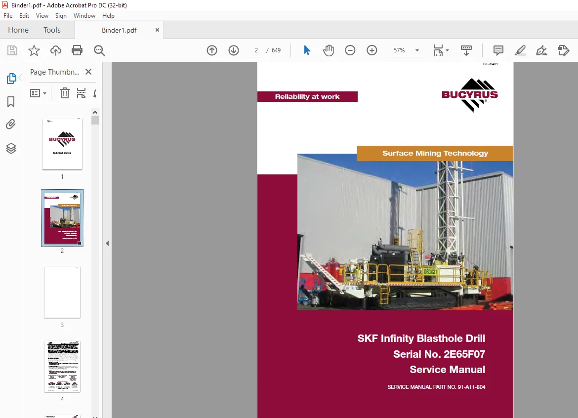
Cat Bucyrus SKF Infinity Blasthole Drill Service Manual SN 2E65F07 – PDF DOWNLOAD
$31.95
Cat Bucyrus SKF Infinity Blasthole Drill Service Manual SN 2E65F07 – PDF DOWNLOAD
Description
Cat Bucyrus SKF Infinity Blasthole Drill Service Manual SN 2E65F07 – PDF DOWNLOAD
FILE DETAILS:
Cat Bucyrus SKF Infinity Blasthole Drill Service Manual SN 2E65F07 – PDF DOWNLOAD
Language : English
Pages : 649
Downloadable : Yes
File Type : PDF
IMAGES PREVIEW OF THE MANUAL:
DESCRIPTION:
Cat Bucyrus SKF Infinity Blasthole Drill Service Manual SN 2E65F07 – PDF DOWNLOAD
Safety:
Before Operation:
• Be sure that prior to starting the machine, all controls are in neutral or off positions and
that controls are in the position that will generate the least load upon the engine on start-up.
Especially ensure the auto pulldown is off and rotation lever is in neutral.
• Be sure that the drill area is clear of all obstructions before operating the machine.
• Ensure that the safety chain is attached when using a towbar.
• Do not operate the machine with: a hydraulic leak, broken or damaged electrical wiring or
damaged hydraulic hoses or fittings.
• Do not operate the machine without familiarising yourself with the location of all hand held
fire extinguishers.
• Be sure the fire suppression system has not been activated, is still pressurised, and that
lines and nozzles are in the correct place and not damaged.
• Do not operate the machine without familiarising yourself with the location of on-board fire
suppression activation points.
• Do not operate the machine without first checking that all emergency stops are operational and
familiarising yourself as to their location.
During Operation:
• Do not use the machine for anything other than its designed purpose for blasthole drilling.
• Do not wear jewellery or loose fitting clothing when working on the machine. Keep clothing and
hands clear of moving parts.
• Do not move the machine if the drill is in a potentially unstable position.
• Always be aware of the drill rigs automated functions and make sure people are clear of
all components. The rotary drill has an automated function of the dust curtain raise/lower
cylinders when the machine is switched from ‘drill’ to ‘propel’ mode.
• Do not propel the machine with the mast raised over undulating ground or across grades or
over any distance other than short distances on a drill pattern.
TABLE OF CONTENTS:
Cat Bucyrus SKF Infinity Blasthole Drill Service Manual SN 2E65F07 – PDF DOWNLOAD
Section 1 – Safety 1-1
Section 1 Contents 1-3
Safety 1-5
Overview of Potential Hazards 1-5
Personal Protective Equipment 1-5
Noise 1-5
Electrical Contact 1-5
Contaminated Air 1-6
Moving and Rotating Parts 1-7
High Pressure Air or Fluid 1-7
Before Operation 1-7
During Operation 1-8
Maintenance 1-10
Equipment Transfer 1-10
Safety Locator 1-11
Notes 1-14
Section 2 – Operator’s Cab / Controls 2-1
Section 2 Contents 2-3
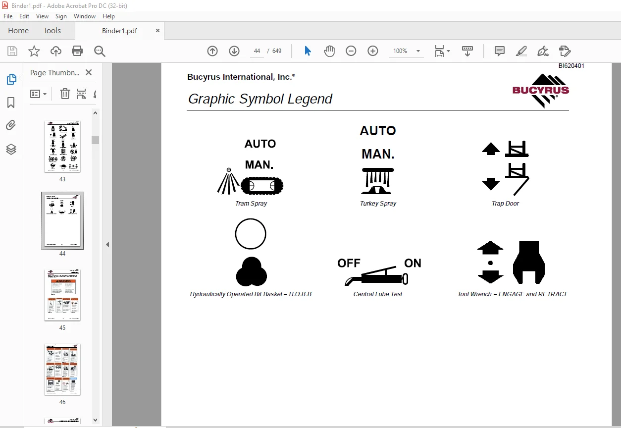
Graphic Symbol Legend 2-5
Graphic Symbol Legend 2-5
Warning Decals 2-9
Warning Decals 2-9
Operator Control and Instrument Panels 2-11
Control Panels 2-11
Right Hand Control Panel 2-11
System Pressure Gauge Panel 2-13
Switch Panel 2-16
Switches / Diagnostic / Control Panel Circuit 2-19
Machine Stability 2-21
Tramming Procedure 2-21
Track Adjustments 2-21
New Machine Procedure 2-22
General Maintenance Checks While Tramming 2-22
Roller Locations 2-23
Temperature and Condition Record Chart for Walking 2-24
Propelling the Machine 2-25
Stability Limits 2-27
SKF Transient Stability Limits 2-28
Cab Heater 2-29
Cab Heater Fault Isolation 2-29
Air Conditioner 2-30
T7 Series Split System Air Conditioning Manual 2-30
Section 1 0 Technical Data and Control Settings 2-31
Section 2 0 Installation and Commissioning 2-33
Section 3 0 Routine Maintenance Procedures 2-39
BI620401
Bucyrus International, Inc ®
SKF-12 Introduction Int-6 September, 11 Version 1
Contents
Section 4 0 Fault Diagnosis 2-40
Section 5 0 Reference Drawings 2-49
Notes 2-54
Section 3 – Main Frame / Crawlers 3-1
Section 3 Contents 3-3
Main Frame Repair – General 3-5
Main Frame Repair 3-5
Weld Inspection Schedule 3-6
Main Frame 3-6
Levelling Jacks 3-7
Levelling Jacks Cylinder 3-7
Levelling Jacks 3-8
Limit Switch 3-8
Levelling Jack Cylinders 3-8
Mast Elevating Cylinders 3-9
Mast Elevating Cylinders 3-9
Internal Counterbalance Valve 3-10
Fuelling Valves 3-12
Hydrau-Flo® Fuelling Valves 3-12
Crawler Assembly 3-14
Crawler Assembly 3-14
Crawler Component Repair 3-15
Tramming 3-16
Maintenance checks for Tramming 3-16
Track Adjustments 3-16
New Machine Procedure 3-17
General Maintenance Checks While Tramming 3-17
Roller Locations 3-18
Temperature and Condition Record Chart for Walking 3-19
Metric Bolt Torque 3-20
Metric Bolt Torque Specifications 3-20
Track Maintenance 3-21
Before Operating the Machine 3-21
General Maintenance 3-21
Track Tension 3-22
Track Assembly 3-22
Hydraulic Tensioner 3-24
Track Tension Unit 3-25
Track and Support Rollers 3-26
Track Roller 3-26
Track Roller Unit 3-27
Track Roller – Assembly 3-28
Track Roller – Test and Install 3-29
Support Roller 3-31
BI620401
Bucyrus International, Inc ®
September, 11 Version 1 Int-7 SKF-12 Introduction
Contents
Track Chain 3-35
Track Chain 3-35
Track Shoes Installation 3-38
Track Link Position 3-38
Track Shoe – Mounting to Track Chain 3-38
Track Shoe Bolt Torque (Direct Torque Method) 3-40
Bolt Torque KN111 3-40
Track Shoe Bolt Torque (Torque Turn Method) 3-41
Bolt Torque KN111 3-41
Track Chain and Shoe Installation 3-42
Track Chain with Shoes 3-42
Final Drive Unit 3-44
Final Drive Unit 3-44
Removal from Track Frame 3-45
Installation into Track Frame 3-46
Final Drive Maintenance 3-47
Final Drive Oil 3-48
Final Drive Assembly 3-50
Parking Brake – Description 3-51
General Description 3-52
General Recommendations for Disassembly and Assembly Operations 3-52
Final Drive – Disconnect and Parking Brake 3-54
Towing Procedure – Gear Drive Disconnect 3-54
Parking Brake 3-55
Sealing Compounds and Adhesives 3-56
Filling and Checks 3-58
Service Schedule 3-58
Tightening Torques 3-59
Lubrication / Greasing – Grades and Application Range 3-59
Troubleshooting 3-60
Special Tools 3-60
Idler Unit 3-61
Idler Unit 3-61
Track and Sprocket Inspection 3-65
Track Inspection and Wear Limit Guide 3-65
Sprocket Wear Patterns 3-70
Auxiliary Crane 3-76
Hydraulic Crane 3-76
Notes 3-78
Section 4 – Engine / Drive Train / Compressor 4-1
Section 4 Contents 4-3
Power Group Locator 4-7
Power Group Locator 4-7
Test Point Locator 4-8
Test Point Locator 4-8
BI620401
Bucyrus International, Inc ®
SKF-12 Introduction Int-8 September, 11 Version 1
Contents
Cummins Engine 4-10
Cummins Engine 4-10
QST30 Electric Fuel Supply System 4-11
Construction 4-12
Electric Fuel Supply Pumps 4-12
Combo Fuel Filter Head and Pump Manifold 4-12
FS1006 Fuel Filter with Water Separator 4-12
Fuel Manifold with Integrated FSO Valve 4-13
Fuel Connections 4-13
Pre-filters 4-13
Wiring with EFS Power Relay 4-14
Pressure and Temperature Sensors 4-14
Operation 4-15
QST30 Electric Fuel Supply System Flow Diagram 4-16
QST30 Electric Fuel Supply System Detail 4-17
Oil Reserve Systems 4-18
LED Monitor Readings 4-19
Adjustment of Running Oil Level 4-19
Wiring Diagram – Oil Reserve Basic Circuit 4-20
Oil Pressure Switch 4-20
Oil Reserve System 4-20
Troubleshooting 4-21
Maintenance 4-21
Engine and Compressor Air Cleaners 4-22
Engine and Compressor Air Cleaner Service Assembly 4-22
Engine and Compressor Air Cleaner Service 4-23
Flexible Drive Coupling 4-26
Flexible Drive Coupling Service 4-26
Pump Drive 4-28
Pump Drive Assembly – Removal and Replacement 4-28
Pump Drive Gearbox 4-29
Pump Drive Gearbox Repair 4-29
Hydraulic Pumps 4-31
Pump Arrangement 4-31
Hydraulic Pumps – Removal and Replacement 4-32
Compressor Installation 4-33
Compressor Assembly 4-33
Safety 4-34
Compressor Installation 4-37
Compressor Alignment 4-39
Mounting Instructions for Arcusaflex™ Flywheel Couplings 4-40
Taper-Loc Bushing Installation – Model AC-T5 SN F2 V1 3535 4-41
Tightening Torques for Arcusaflex™ Flywheel Couplings 4-41
Compressor Shaft Seal 4-42
Compressor Shaft Seal 4-42
BI620401
Bucyrus International, Inc ®
September, 11 Version 1 Int-9 SKF-12 Introduction
Contents
High Pressure Compressor 4-44
Description 4-44
Compressed Air Functions 4-44
Compressor Oil Circuit – 1475cfm @ 500psi 4-48
Compressor Condensation Table 4-51
Compressor Air Circuits – 1475cfm @ 500psi 4-52
Compressor Air Circuit Diagram Legend 4-54
Compressor Air Circuit – 1475cfm @ 500psi 4-55
Compressor Functional Description 4-67
Operation 4-70
Compressor Maintenance 4-73
General Maintenance 4-73
Interstage Tube 4-75
Discharge Check Valve 4-76
Separator / Receiver Tank 4-77
Scavenge Line 4-79
Compressor Discharge Temperature Switches, Senders and Gauges 4-80
Minimum Pressure / Check Valve 4-81
Minimum Pressure / Check Valve Maintenance 4-81
Thermal Bypass Valve 4-82
Thermal Bypass Valve Maintenance 4-83
Compressor Fluid Filter 4-84
Changing Filter Elements 4-85
Fluid Stop Valve 4-86
Inlet Valve 4-88
Compressor Regulation 4-90
Relieving Regulators 4-90
Reducing Regulators 4-92
System Blowdown Valve 4-94
Running Blowdown Valve 4-95
Moisture Separator Maintenance 4-97
Auxiliary Regulator 4-97
Troubleshooting 4-101
Coolers 4-103
Fan / Oil Cooler Piping 4-103
Fan and Motor Installation 4-104
Aluminium Tube Air to Oil Cooler 4-105
High Pressure Air to Oil Coolers – Standard Parts 4-105
Repair Instructions – External Cleaning and Tube Removal 4-106
Repair Instructions – Seal Removal, Header Plate Preparation and Seal Installation 4-107
Repair Instructions – Special Header Plate Repair 4-109
Radiator Cooler 4-111
Typical Radiator Core – Standard Parts 4-111
Cleaning 4-112
Tube Removal 4-113
Seal Installation 4-114
BI620401
Bucyrus International, Inc ®
SKF-12 Introduction Int-10 September, 11 Version 1
Contents
Lubricating Seals and Tube Ends 4-114
Tube Installation 4-115
Notes 4-118
Section 5 – Dust Control System 5-1
Section 5 Contents 5-3
Dust Control System 5-5
Dust Control Systems 5-5
Water Injection 5-7
Water Tanks 5-7
Water Injection Pump 5-8
Water Injection Relief Valve 5-8
Water Injection Control 5-9
Water Injection Basic Circuit 5-11
Water Pump 5-12
Water Injection Pump Assembly 5-12
Pump Specifications 5-13
Torque Requirements 5-13
Servicing Instructions 5-13
Servicing the Plunger Packings 5-13
Reassembling Plunger Packings 5-14
Servicing the Pump Valves 5-14
Reassembling Valve Parts 5-14
Servicing the Crankshaft 5-15
Servicing the Crossheads 5-15
Replacing Piston Cup Seals 5-16
Replacing Suction and Discharge Valves 5-17
Replacing Power End Bearings 5-18
Servicing the Wrist Pin Bearings 5-19
Fastener Torque Requirements 5-19
Recommended Lubricants 5-20
Water Pump Motor Repair 5-20
Water Pump Drive Coupling 5-20
Level and Flow Transducer 5-20
Notes 5-21
Section 6 – Mast / Rotary Drive / Pipe Rack 6-1
Section 6 Contents 6-3
Mast Weldment 6-5
Mast Repair 6-5
Weld Inspection Schedule 6-6
Mast Inspection 6-6
Mast Assembly and Installation 6-7
Mast Assembly 12m 6-7
Mast Pivot Caps 6-8
Mast Elevate Cylinders 6-9
BI620401
Bucyrus International, Inc ®
September, 11 Version 1 Int-11 SKF-12 Introduction
Contents
Angle Drilling 6-9
Mast Assembly 6-10
Raising the Mast 6-10
Feed Cylinders 6-12
SKF Feed System 6-12
Removal 6-13
SKF-12 Feed Cylinder 6-14
Repair 6-15
Installation 6-15
Hoist / Pulldown Cable 6-16
Cable Tensioning 6-16
Auto Tensioning – Operating Principle 6-17
Auto Tensioning – Cable Removal, Installation and Adjustment 6-17
Rope Tensioning 6-19
Wire Rope 6-21
Rotary Drive 6-22
Alignment Procedure 6-22
Rotary Drive Assembly 6-23
Rotary Drive – Removal from Mast 6-24
Rotary Drive – Installation 6-24
Single Motor Rotary Drive Gearbox 6-25
Manufacturers Recommendations – Blast Hole Drilling Consumables 6-26
Air Swivel (Single Seal Style) 6-27
Rotary Drive Motor – Repair 6-28
Torque Limit Table Grade 8 UNC 6-29
Torque Limit Table Grade 8 UNF 6-30
Rotary Drive Motor 6-31
Deck Wrench 6-32
Deck Wrench 6-32
H O B O Wrench 6-33
H O B O Wrench 6-33
Tong Dies 6-34
Optional Hydraulic Operated Bit Basket – H O B B 6-35
Pipe Positioner 6-36
Pipe Positioner 6-36
Carousel Pipe Rack 6-37
Carousel Pipe Rack 6-37
Chain Drive – Adjustment / Replace 6-37
Pipe Rack Bearings – Replace 6-38
Carousel Top Tube Bearing – Replace 6-39
Carousel Lower Bearing – Replace 6-41
Upper Pivot Support Bearing 6-42
Carousel Pivot Support Upper Bearing – Replace 6-43
Pivot Support Pipe Lower Bushing 6-44
Carousel Pivot Support Lower Bearing – Replace 6-45
Mid Point Carousel Pivot Support 6-46
Carousel Rotate Motor 6-46
Notes 6-47
BI620401
Bucyrus International, Inc ®
SKF-12 Introduction Int-12 September, 11 Version 1
Contents
Section 7 – Hydraulic Systems 7-1
Section 7 Contents 7-3
Hydraulic Symbols 7-7
Hydraulic Symbols 7-7
Pressure Setting Sequence 7-9
Pressure Setting Sequence 7-9
Hydraulic System 7-9
Main Hydraulic Pumps 7-10
Pump Arrangement 7-10
Hydraulic Tank 7-11
Hydraulic Tank 7-11
Hydraulic System 7-12
Main Return and Case Drain Filter 7-13
Routine Maintenance 7-14
Changing Filter Elements 7-14
Loop Filters 7-15
Loop Filters 7-15
Loop Filter cross section 7-16
Filter Assembly Loop 7-17
Changing Filter Elements 7-18
Charge Circuit 7-19
Routine Maintenance 7-19
Changing Filter Elements 7-20
Charge Pumps 7-22
Charge Circuit Schematic 7-23
Main Pumps Circuit 7-24
Main Pumps Circuit 7-24
Right Track / Left Track / Rotation Pumps 7-25
Linde Hpv-02 Bi-directional Variable Displacement Closed Loop Pump 7-25
Dimensions 7-27
Operational Parameters 7-28
Linde HPV-02 Pump Schematic 7-29
Controls 7-30
Hydraulic Piston Pumps – Removal and Replacement 7-33
Main Pumps 7-33
EP (24V DC) Control 7-33
Main Pump Adjustments 7-34
Technical Data 7-35
Setting Linde HPV-02 Main pumps – Neutral Setting 7-36
Setting Linde HPV-02 Main pumps – Pressure Settings 7-37
Setting Linde HPV-02 Main pumps – Pre-setup Checks 7-38
Main Pumps Linde HPV-02 7-39
Brake Test Procedure 7-40
Diverter Valve 7-42
Closed Loop Pump Circuit 7-42
BI620401
Bucyrus International, Inc ®
September, 11 Version 1 Int-13 SKF-12 Introduction
Contents
Operation 7-42
Diverter Valve 7-42
Rotation Circuit 7-43
Basic Rotation Circuit 7-43
Basic Right Track / Pulldown and Hoist 7-44
Rotation Circuit Schematic 7-45
Rotation Circuit 7-46
Tram Circuit 7-47
Operation 7-47
Tram Circuit Schematic 7-48
Rotary Drive Gearbox Motor 7-49
Variable Displacement Rotation Motor 7-49
Pilot Control Manifold 7-53
Pilot Control Manifold Assembly 7-53
Proportional Valve set-up 7-63
Auto Pulldown Card 7-63
OEM Controllers / EP Levers 7-64
Auxiliary Functions / Fan Circuit 7-65
Auxiliary / Fan Pump Operation 7-65
Auxiliary Priority Function 7-67
Linde HPR-02 Self-Regulating Pump 7-68
Auxiliary Pump Circuit Schematic 7-69
Feed and Auxiliary Functions Pump 7-70
Linde HPR-02 Self-Regulating Pump 7-71
Hydraulic Piston Pumps – Removal and Replacement 7-72
Auxiliary Circuit 7-74
Auxiliary Circuit Functions 7-74
Auxiliary Valves 7-76
Counterbalance Valves 7-79
Counterbalance Valve Adjustments 7-79
Internal Counterbalance Valve 7-80
Levelling Jack Cylinders 7-82
Jack Leg Cylinder 7-82
Counterbalance Valve Test Procedure 7-82
Mast Elevating Cylinders 7-83
Mast Elevating Cylinders 7-83
Jack Control and Mast Elevating Circuit 7-84
4 Bank Valve 7-84
Hydraulic Operated Breakout Wrench 7-85
H O B O Wrench 7-85
Setting of H O B O Sequence Valves 7-86
H o b o Float Valve 7-86
Hoist and Pulldown Control 7-87
Hoist / Pulldown Circuit Schematic 7-87
Control Valve Assembly 7-88
Technical Data 7-88
BI620401
Bucyrus International, Inc ®
SKF-12 Introduction Int-14 September, 11 Version 1
Contents
Cooler Fan Circuit 7-89
Cooler Fan Circuit 7-89
Cooler Fan Circuit Schematic 7-91
Hydraulic cooler – Thermal valve 7-92
Basic Cooler Fan Circuit 7-93
Cooler Fan Motor 7-94
Cooler Fan Motor Assembly 7-94
Hydraulic Motor 7-95
Water Pump Motor 7-98
Water Pump Motor Repair Information 7-98
Shaft Seal Repair 7-99
Hydraulic Cylinder Repair 7-102
Hydraulic Cylinders 7-102
General Information 7-103
H Head 7-105
N Head 7-106
Z Head 7-107
Z Head (Two Piece) 7-108
K Head 7-109
M Head 7-110
Z Piston 7-111
Z Piston (Threaded) 7-112
H and K Piston 7-113
M Piston 7-114
N Piston 7-117
Notes 7-118
Section 8 – Electrical Components 8-1
Section 8 Contents 8-3
Electrical Locator 8-5
Electrical Component Location 8-5
Jump Starting 8-8
Jump Starting 8-8
Batteries 8-10
Batteries 8-10
Welding Precautions 8-11
Welding Precautions 8-11
Electrical Components 8-12
Electrical Circuits 8-12
Transducers 8-12
EP Levers 8-13
Joystick Adjustments 8-14
Vigilante Guide 8-16
Important Information 8-16
PLC 8-17
Touchscreen 8-20
BI620401
Bucyrus International, Inc ®
September, 11 Version 1 Int-15 SKF-12 Introduction
Contents
Laser Depth System 8-21
Distance Meter 8-24
Start-up and Shutdown 8-24
Hydraulic Function Enable 8-24
Alarms 8-25
Solenoid Control 8-25
Auto Lube 8-28
Hammer Oil Systems 8-28
Gauges 8-28
Level Switches 8-31
Head Speed Module 8-31
Dust Suppression 8-32
Acknowledgements 8-32
Disclaimers 8-32
Notes 8-33
N B: For further information on specific electronic components, please refer to
Vendor Documents in Table of Contents on Service Manual CD
Section 9 – Lubrication and Preventive Maintenance 9-1
Section 9 Contents 9-3
Central Lube System 9-5
Auto Lube Basic Operation 9-5
Central Lube Tank Assembly 9-6
Auto Lube Grease Pump 9-7
Auto Lube Tube Pump 9-13
Graco Vent Valve 9-18
Central Lube System Circuit 9-19
Basic Operational Principles of Auto Lube Injectors 9-20
SL-V and SL-V XL Injectors 9-20
SL-1 and Sl-11 Injectors 9-21
SL-32 Injectors 9-22
Typical Grease System Circuit 9-23
First 50 Hours Service 9-24
Lube Faults / Operation 9-25
Auto Lube Timer 9-26
Lube Pressure Screen 9-26
Hammer Oil Tank 9-27
Hammer Oiler Tank Assembly 9-27
Hammer Oil Circuit 9-28
10:1 Hammer Oil Pump Instructions 9-29
Installation 9-31
Operation 9-34
Troubleshooting 9-35
Air Motor and Throat Service 9-36
Displacement Pump Service 9-40
Parts List 9-41
BI620401
Bucyrus International, Inc ®
SKF-12 Introduction Int-16 September, 11 Version 1
Contents
Parts Drawing 9-42
Dimensions 9-43
Technical Data 9-43
Performance Chart 9-44
Air Service Units 9-45
Air Service Unit 9-45
Filter Regulator 9-46
Air Line Oiler 9-47
Soft Start Dump Valve 9-48
Pipe Thread Lubricator 9-49
Air Operated Pipe Thread Pump 9-49
Filter Locator 9-57
Filter Locator Assembly 9-57
Lubrication and Preventive Maintenance 9-58
General Lubrication 9-58
Equipment Lubrication 9-58
Care of Lubrication Points 9-58
Safety 9-59
Isolation Battery Switch 9-60
Track Gear 9-61
Engine Maintenance 9-62
Air Cleaners 9-63
Air Filter Elements 9-63
Alternator Maintenance 9-63
Pump Drive and Drive Shaft Maintenance 9-64
Compressor Maintenance 9-64
Cooler Packs 9-64
A-frame and Pivot Point Maintenance 9-66
Pulldown and Hoist Ropes and Sheaves Maintenance 9-66
Rotary Head Maintenance 9-66
Hydraulic System Maintenance 9-68
Hydraulic Maintenance 9-68
Water Pump Maintenance 9-68
Cab Maintenance 9-68
Air Conditioner Maintenance 9-70
Battery Maintenance 9-70
Lubrication System Maintenance 9-70
Fire Suppression Maintenance 9-70
Drill Folding Stairway – Inspection Requirements 9-72
Weld Inspection Schedule 9-73
Weld Inspection Schedule SK Series 9-73
Track and Sprocket Inspection 9-74
Track Inspection and Wear Limit Guide 9-74
Sprocket Wear Patterns 9-79
Lubrication Recommendations 9-85
Lubrication Recommendations 9-85
BI620401
Bucyrus International, Inc ®
September, 11 Version 1 Int-17 SKF-12 Introduction
Contents
Lubrication and Maintenance Chart – 250hr 9-86
Lubrication and Maintenance Chart – 500hr 9-96
Lubrication and Maintenance Chart – 1000hr 9-107
Lubrication and Maintenance Chart – 2000hr 9-118
Lubricant Specifications 9-130
Hydraulic System 9-130
Hydraulic Tank Capacity 9-130
Compressor Lubrication 9-131
Compressor Lubricant Specifications 9-131
Lubricating Grease 9-132
Gear Lubricant 9-132
Scheduled Oil Sampling Analysis 9-132
Critical Fasteners 9-133
Bolted Joint Maintenance Guide Rotary Drills 9-133
Critical Fasteners ID and Inspection Schedule 9-135
Torque Values 9-136
Externally Threaded SAE – ASTM Fasteners 9-136
SAE Recommended Torque Values 9-137
Torque Values 9-138
Notes 9-139
Contact us: [email protected]
https://vimeo.com/867133912?share=copy
PLEASE NOTE:
- This is the SAME exact manual used by your dealers to fix your vehicle.
- The same can be yours in the next 2-3 mins as you will be directed to the download page immediately after paying for the manual.
- Any queries / doubts regarding your purchase, please feel free to contact [email protected]
S.V