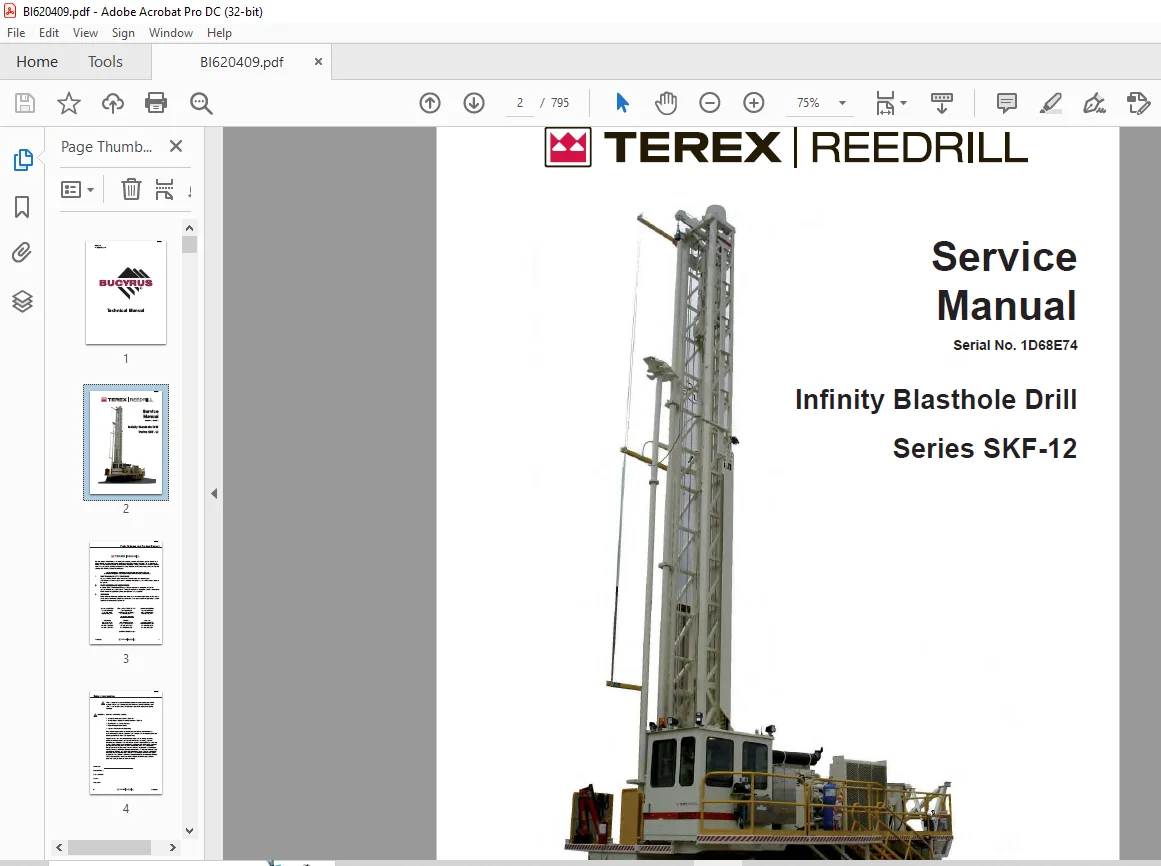
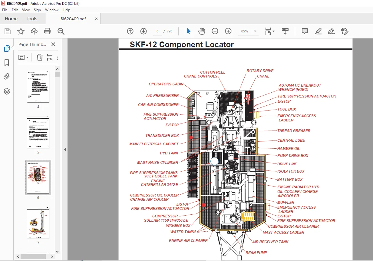
Cat Bucyrus Terex Series SKF-12 Infinity Blasthole Drill Service Manual SN 1D68E74 – PDF DOWNLOAD
$32.95
Cat Bucyrus Terex Series SKF-12 Infinity Blasthole Drill Service Manual SN 1D68E74 – PDF DOWNLOAD
Description
Cat Bucyrus Terex Series SKF-12 Infinity Blasthole Drill Service Manual SN 1D68E74 – PDF DOWNLOAD
FILE DETAILS:
Cat Bucyrus Terex Series SKF-12 Infinity Blasthole Drill Service Manual SN 1D68E74 – PDF DOWNLOAD
Language : English
Pages : 795
Downloadable : Yes
File Type : PDF
IMAGES PREVIEW OF THE MANUAL:
DESCRIPTION:
Cat Bucyrus Terex Series SKF-12 Infinity Blasthole Drill Service Manual SN 1D68E74 – PDF DOWNLOAD
Safety:
The Rotary Drill is a heavy moving machine with a mast which raises vertically for drilling. Like
all moving objects and reach extending devices, there are potential hazards associated with its
use. These hazards will be minimised if the machine is properly inspected and maintained. The
maintainers must read this manual and have been trained to use the machine in an appropriate and
safe manner. Should any questions arise concerning the maintenance or operation of the machine
contact Reedrill in your state or territory.
There are many personal hazards and dangers associated with working on and around a drill rig. If
the safety instructions outlined in this section are adhered to, risk of injury or harm to yourself
and others will be signi cantly reduced.
In this section and those that follow, the word:
● DANGER means that severe injury or death will result from failure to follow instruction
● WARNING means that severe injury or death can result from failure to follow instruction
● CAUTION means that minor injury or property damage can result from failure to follow
instruction
● NOTE means that special attention should be given to the instruction
Personal Protective Equipment:
Ensure that the minium PPE is worn at all times when operating or maintaining the machine. Speci
c PPE may be required when undertaking some tasks or repairs. For example working at height,
welding or grinding repairs.
Noise:
The Rotary Drill generates high noise while it is in operation therefore, hearing protection is
mandatory whenever working in the vicinity of the drill.
Electrical Contact:
The Mines Regulation 5.28 states that unless minimum clearances under
and in the vicinity of overhead power lines in accordance with AS 3007.5 can be assured, no
drilling activity can take place within 10 meters any electrical power-line.
Overhead and Buried Utilities:
● Should be located, noted and emphasised on all drilling location plans and drilling
assignment sheets.
● Whenever overhead power lines exist on or near a drilling site or project, consider all
wires to be live and dangerous.
● Watch for sagging power lines before entering a site. Do not lift power lines to gain
entrance.
● Before raising a drill rig mast on a site in the vicinity of power lines, walk completely
around the rig. Determine what the minimum distance from any point on the drill rig to the nearest
power line will be when the mast is raised or being raised.
● Do not raise the mast or operate the drill rig within a minimum of 10 meters of any
electrical power line or underground utility without a permit indicating “danger zones” and minimum
clearances.
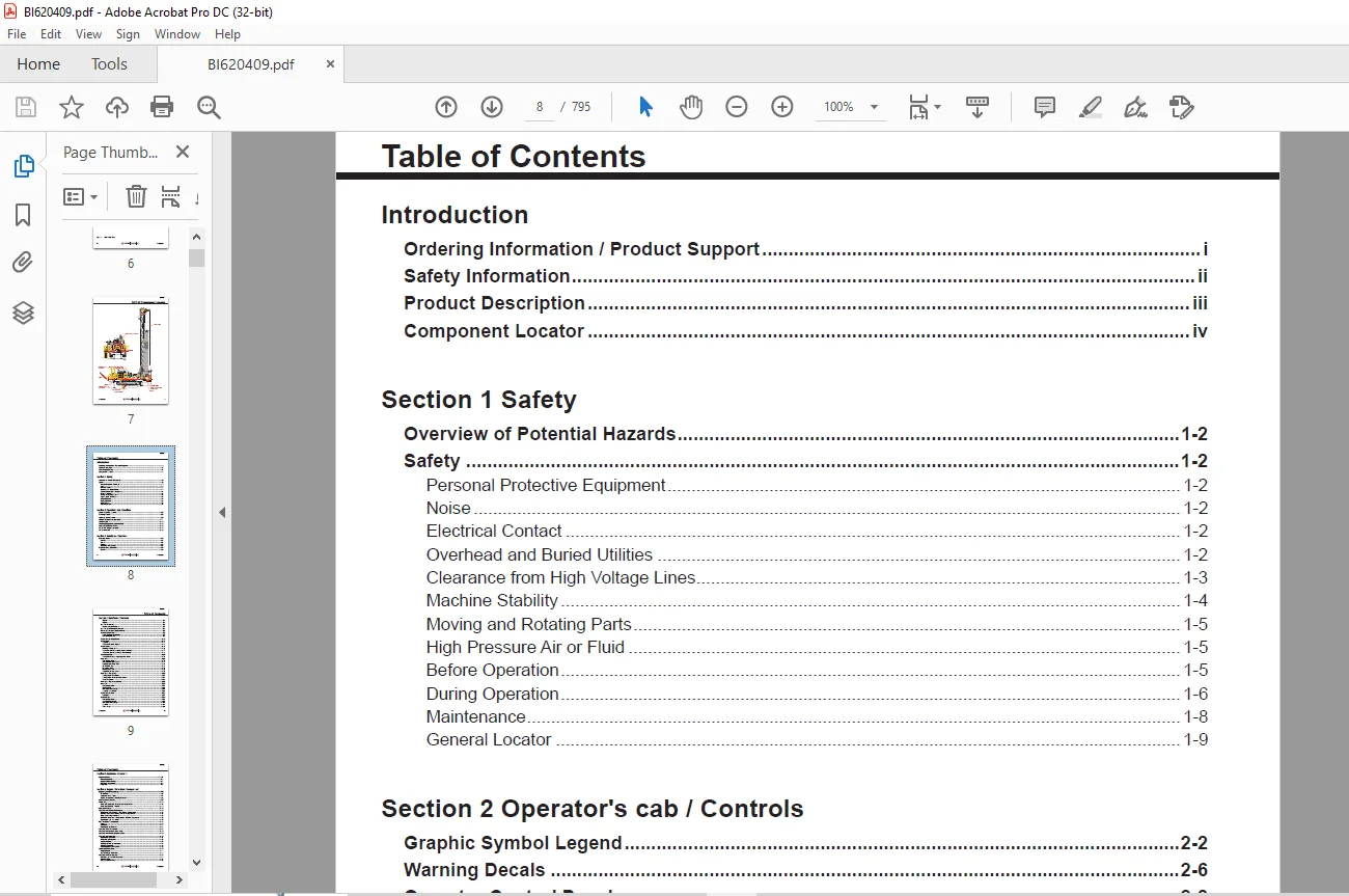
TABLE OF CONTENTS:
Cat Bucyrus Terex Series SKF-12 Infinity Blasthole Drill Service Manual SN 1D68E74 – PDF DOWNLOAD
Introduction
Ordering Information / Product Support i
Safety Information ii
Product Description iii
Component Locator iv
Section 1 Safety
Overview of Potential Hazards 1-2
Safety 1-2
Personal Protective Equipment 1-2
Noise 1-2
Electrical Contact 1-2
Overhead and Buried Utilities 1-2
Clearance from High Voltage Lines 1-3
Machine Stability 1-4
Moving and Rotating Parts 1-5
High Pressure Air or Fluid 1-5
Before Operation 1-5
During Operation 1-6
Maintenance 1-8
General Locator 1-9
Section 2 Operator’s cab / Controls
Graphic Symbol Legend 2-2
Warning Decals 2-6
Operator Control Panel 2-8
System Pressure Gauge Panel 2-11
Switch Panel 2-12
Switches/Diagnostic Control Panel 2-15
Cab Heater Fault Isolation 2-16
AC/Heater/Pressurizer Unit 2-17
Air Conditioner 2-18
Section 3 Mainframe / Crawlers
Leveling Jacks 3-2
Remove 3-3
Repair 3-3
Replace 3-3
Lubricating Jack Casings 3-3
Mast Elevating Cylinders 3-4
Remove 3-5
BI620409
Introduction vii
Section 3 Mainframe / Crawlers
Table of Contents
Repair 3-5
Replace 3-5
Crawler Assembly 3-6
Crawler Component Repair 3-7
Crawler Serial Number Location 3-7
Metric Bolt Torque Specifi cations 3-8
Track Maintenance 3-9
Before Operating the Machine 3-9
General Maintenance 3-9
Track Tension Adjustment 3-10
Track Chain 3-12
Separate 3-12
Track Link Repair & Replace 3-14
Track Shoes 3-16
Mounting to Track Chain 3-16
Track Shoe Bolt Torque (Direct Torque Method) 3-17
Track Shoe Bolt Torque (Torque Turn Method) 3-17
Track Assembly 3-20
Track Chain & Shoe – Assembly & Installation 3-20
Final Drive 3-22
General Description 3-22
Removal from Track Frame 3-23
Installation into Track Frame 3-24
Oil Check/Change 3-25
Oil Specifi cations 3-26
Recommended Oils 3-26
Temperature Range Chart 3-27
Final Drive Assembly 3-28
Parking Brake – Description 3-30
Parking Brake – Removal & Installation 3-31
Towing Procedure 3-31
Final Drive Assembly Manual 3-33
Idler Unit 3-90
General Description 3-90
Idler Assembly 3-91
Removal & Disassembly 3-92
Assembly & Installation 3-94
Track Tension Unit 3-96
Installation 3-97
Track Rollers 3-98
General Description 3-98
Track Roller Assembly 3-99
Removal & Disassembly 3-100
Assembly 3-101
Test & Install 3-102
BI620409
viii Introduction
Table of Contents
Section 4 Engine / Drive train / Compressor
Engine Service Procedures 4-3
Power Train 4-3
Caterpillar 3412E Engine 4-4
Engine and Compressor Air Cleaner Service 4-5
Flexible Drive Coupling 4-6
Pump Drive 4-10
Pump Drive Assembly – Removal and Replacement 4-10
Pump Drive Gearbox – Repair 4-12
Hydraulic Pumps 4-13
Compressor Service Procedures 4-15
Compressor Drive Coupling – Removal and Replacement 4-16
Mounting Instructions for Arcusafl ex Flywheel Couplings 4-18
Taper-Loc Bushing Installation 4-18
Before Installation and Start-Up of New or Rebuilt Compressor 4-19
Compressor Unit – Installation 4-19
High Pressure Compressor 4-20
Safety 4-20
Description 4-23
Compressed Air Functions 4-23
Compressor Fluid Circuit 4-27
Compressor Condensation Table 4-29
Compressor Functional Description 4-30
Compressor Operation 4-33
Compressor Air Circuit 4-38
Initial Start-up Procedure 4-39
Regulator Set-up 4-39
Subsequent Start-up Procedure 4-40
Shutdown Procedure 4-40
General Operating Instructions 4-40
General Maintenance 4-40
Daily Operation 4-41
50, 250, 500, & 1000 Hours 4-41
Compressor Maintenance 4-42
Main Drive Shaft Seal Replacement 4-42
Interstage Tube 4-44
Discharge Check Valve 4-45
Support Rollers 3-103
General Description 3-103
Support Roller Assembly 3-104
Removal & Disassembly 3-105
Assembly 3-106
Section 3 Mainframe / Crawlers
BI620409
Introduction ix
Table of Contents
Section 5 Dust Control Systems
Dust Control System Functions 5-2
Basic Water Injection Circuit 5-2
Water Injection Circuit 5-3
Dust Collector/Water Injection Pressure Adjustment 5-5
Water Pump Assembly 5-6
Water Pump Service Manual 5-7
Water Pump Motor Service Manual 5-32
Section 6 Mast / Rotary drive / Pipe rack
12 Meter Mast Assembly 6-2
Cable Tensioning Assembly 6-3
Feed Cylinder – Removal and Installation 6-4
SKF-12 Feed Cylinder 6-6
Cylinder Repair 6-7
Hoist / Pulldown Cable Adjustment 6-8
Auto Tensioning (optional) – Operating Principle 6-11
Auto Tensioning – Cable Installation & Adjustment 6-14
Hoist / Pulldown Cable Replacement 6-16
Rotary Head Guide Alignment 6-17
Separator/Receiver Tank 4-46
Minimum Pressure Check Valve 4-47
Scavenge Line 4-48
Compressor Discharge Temperature Switches, Senders, & Gauges 4-49
Thermal Bypass Valve 4-51
Compressor Fluid Filter 4-54
Fluid Stop Valve 4-56
Inlet Valve 4-58
Relieving Regulators 4-59
Reducing Regulators 4-61
System Blowdown Valve 4-63
Running Blowdown Valve 4-64
Moisture Separator 4-66
Troubleshooting 4-66
Recommended Spare Parts Listing 4-68
Fan/Oil Cooler Piping 4-69
Fan Motor and Fan Installation 4-70
Radiator/Oil Cooler Repair 4-72
Mesabi Radiator & Cores Service Manual 4-73
High Pressure Compressor Fluid Cooler 4-81
Section 4 Engine / Drive train / Compressor
BI620409
x Introduction
Rotary Drive Assembly 6-19
Removal from Mast 6-20
Installation 6-20
Rotary Drive Gearbox 6-21
Rotary Drive Assembly and Parts List 6-21
Rotary Drive Gearbox – Repair Manual 6-23
Air Swivel 6-63
Rotary Drive Motor – Repair 6-26
Winch Assembly 6-66
Precautions on the Use of Winches 6-66
Wire Rope 6-66
Wedge Sockets 6-68
Grooved Drums 6-69
Plain (Smooth) Drums 6-69
Drums – Multiple Layers 6-71
Winch Service Manual – Model BG8A 6-73
Deck Wrench 6-104
H O B O Wrench 6-105
Tong Dies 6-106
Pipe Positioner 6-107
Carousel Pipe Rack 6-108
Chain Drive – Adjust/Replace 6-108
Pipe Rack Bearings – Replace 6-109
Carousel Top Tube Bearing – Replace 6-110
Carousel Lower Bearing – Replace 6-113
Carousel Pivot Support Upper Bearing – Replace 6-115
Carousel Pivot Support Lower Bearing – Replace 6-117
Carousel Pivot Support Mid-Point Bearing – Replace 6-118
Section 7 Hydraulic systems
Hydraulic Symbols 7-2
Hydraulic Tank 7-4
Hydraulic System 7-5
Pressure Setting Sequence 7-6
Main Return and Case Drain Filters 7-7
Routine Maintenance 7-8
Changing Filter Elements 7-8
Main Hydraulic Pumps 7-9
Hydraulic Pump – Identifi cation 7-9
Hydraulic Piston Pumps – Removal and Replacement 7-10
Right Track/Pulldown, Left Track/Rotation Pumps 7-6
Technical Data 7-11
AA4VG 125 Hydraulic Pump EP2 Control 7-13
Table of Contents
Section 6 Mast / Rotary drive / Pipe rack
BI620409
Introduction xi
Table of Contents
Section 7 Hydraulic systems
AA4VG EP Contoller 7-14
EP (24VDC) Control 7-15
Adjustment of Drill and Tram Controllers 7-16
Start-Up Procedure 7-17
Connections 7-19
Before Making Pump Adjustments 7-20
Mechanical Zero Position Adjustment 7-21
Hydraulic Centering Adjustment 7-22
Set Charge Pressure 7-24
Set Pressure Override (P O R ) 7-24
Set Crossover Relief (High Pressure) 7-26
Removal and Installation 7-27
Hydraulic Piston Pumps – Maintenance 7-28
Hydraulic Piston Pump – Trouble Shooting 7-30
Charge Circuit 7-34
Charge Circuit Gear Pump 7-34
Routine Maintenance 7-37
Changing Filter Elements 7-37
Loop Filters 7-38
Routine Maintenance 7-41
Changing Filter Elements 7-41
Diverter Valve 7-42
Operation 7-42
Hydraulic Feed and Rotation Circuits 7-43
Basic Rotation Circuit 7-43
Rotation Circuit 7-44
Basic Pulldown Circuit 7-45
Hoist / Pulldown Circuit 7-46
Drill / Tram Control Circuit 7-47
Operation 7-47
Drill / Tram Circuit 7-49
Rope Tensioning Circuit 7-50
Rotary Drive Gearbox Motor 7-51
Technical Data 7-52
Shaft Seal Replacement 7-58
Installation 7-59
Start-Up Procedure 7-60
Troubleshooting Procedure 7-61
Routine Maintenance 7-64
Port Information 7-65
Fan and Auxiliary Pump Circuit 7-65
Fan and Auxiliary Functions Pump 7-67
Function of Load Sensing Control 7-67
Standby Pressure 7-67
BI620409
xii Introduction
Main Pressure 7-67
Hydraulic Pumps 7-68
Hydraulic Piston Pumps – Removal and Replacement 7-68
Model AA11VLO Hydraulic Piston Pumps – Repair 7-68
New or Rebuilt Hydraulic Pumps – Start-Up 7-70
Start-Up Procedure 7-70
Auxiliary Functions / Fan Circuit 7-72
Operation 7-73
Auxiliary Priority Function 7-78
Cooler Fan Circuit 7-79
Hydraulic Cooler – Thermal Valve 7-80
Cooler Fan Motor 7-81
Jack and Mast Elevate Circuit 7-88
Counterbalance Valve Adjustment 7-90
Mast Elevating Cylinders Counterbalance Valves 7-91
Leveling Jack Cylinders 7-92
Jack Counterbalance Valve Adjustment 7-92
Auxiliary Functions/6 Spool Valve 7-93
3 Bank Valve 7-94
6 Bank Valve 7-94
9 Bank Valve 7-94
Hydraulic Operated Breakout Wrench (HOBO) 7-96
Setting of Sequence Valves 7-96
Carousel Rotate Motor 7-97
Pilot Control Manifold 7-104
Pilot Control Manifold Schematic 7-105
Hydraulic Gear Pumps 7-119
Hydraulic Gear Pumps – Removal and Replacement 7-119
Hydraulic Gear Pumps – Shaft Seal Removal and Replacement 7-120
Dust Collector / Water Injection Circuit 7-122
Pressure Adjustment 7-122
Hydraulic Cylinder Repair 7-124
Section 8 Electrical Components
Electrical Symbols 8-2
Welding Precautions 8-3
Electrical Components 8-4
Electrical Locator 8-5
Machine Isolation 8-5
Batteries and Alternator 8-6
Batteries 8-6
Jump Starting 8-7
Electrical Circuits 8-8
Table of Contents
Section 7 Hydraulic systems
BI620409
Introduction xiii
Transducers 8-8
Joystick Adjustments 8-9
Vigilante Drill Management System 8-12
Drill Mode Screen 8-12
Laser Depth System 8-13
Vigilante System Screens 8-15
Drill Electrical Guide 8-19
Ladder Proximity Switch 8-35
Jacks Proximity Switch 8-35
LDM 40 A Laser 8-36
Radiator Level Switch 8-48
Hammer Oil Level Transducer 8-52
Combined Pressure Sensor 8-54
Access Light Timer 8-63
Rod Counter Proximity Switch 8-64
Engine Flash Codes 3412E 8-65
Caterpillar 3412E Electrical System 8-67
Section 9 Lubrication and Preventive Maintenance
Service Points – SKF-12 9-2
Lubrication and Preventative Maintenance 9-4
Safety Precautions 9-4
Isolation – Battery Switch 9-5
Track Checks and Lubrication 9-5
Engine Checks and Servicing 9-6
Alternator Checks and Servicing 9-7
Air Conditioner Checks and Servicing 9-8
Drive Shaft Checks and Maintenance 9-8
Compressor Checks and Servicing 9-9
Cooler Checks and Servicing 9-10
Hydraulic Checks and Servicing 9-11
A-Frame and Mast Pivot Point Checks and Maintenance 9-12
Rotary Head Check and Service Points 9-13
Checks and Servicing Pull Down/Hoist Sheaves and Maintenance 9-14
Cabin Checks and Service Points 9-15
Fire Suppression Checks and Servicing 9-15
Battery Checks and Servicing 9-16
Bean Pump Checks and Miantenance 9-16
Lubrication System Checks and Servicing 9-17
Lubrication and Maintenance Chart – 250, 750, 1250, 1750 Hrs 9-18
Lubrication and Maintenance Chart – 500, 1500 Hrs 9-27
Lubrication and Maintenance Chart – 1000 Hrs 9-36
Lubrication and Maintenance Chart – 2000 Hrs 9-45
Lubrication – General, Compressor and Winch 9-56
Section 8 Electrical Components
Table of Contents
BI620409
xiv Introduction
Lubricant Specifi cations 9-57
Compressor 9-57
Lubricating Grease 9-57
Gear Lubricant 9-57
Hydraulic System 9-58
Hydraulic Tank Capacity 9-58
Preventative Maintenance 9-59
Hydraulic System Maintenance 9-59
Cooling System Maintenance 9-59
Torque Values for Standard Fasteners 9-62
Torque Values for Split Flange Connections 9-63
Torque Values for Hydraulic Tubes and Fittings 9-64
Section 10 Optional Equipment
Auxiliary Crane 10-2
Palfi nger Hydraulic Crane 10-2
Remote Winch Control 10-33
Auto Lube System 10-34
Description 10-34
Lube Pump Air Motor 10-35
Parts List 10-37
Service and Disassembly 10-38
Troubleshooting 10-39
Lube Pump Tube 10-40
Service and Operating Procedures 10-40
Parts List 10-42
Disassembly and Troubleshooting 10-43
SL-1 Injector Assembly 10-44
Parts List 10-44
Operation 10-45
Auto Lube System 10-46
Filter/Regulator/Lubricator 10-46
Filter Maintenance and Repair 10-47
Regulator Maintenance and Repair 10-48
Lubricator Maintenance and Repair 10-49
Pipe Thread Lubricator 10-50
Air Service Unit 10-50
Filter Regulator 10-51
Air Line Regulator 10-52
Pipe Thread Pump 10-53
Hammer Oiler Tank Assembly 10-61
Hammer Oiler Circuit 10 62
Hammer Oil System 10 63
Air Service Unit Components 10-63
Filter Regulator 10-64
Air Line Oiler 10-65
Hammer Oil Pump 10-66
Contact us: [email protected]
PLEASE NOTE:
- This is not a physical manual but a digital manual – meaning no physical copy will be couriered to you. The manual can be yours in the next 2 mins as once you make the payment, you will be directed to the download page IMMEDIATELY.
- This is the same manual used by the dealers inorder to diagnose your vehicle of its faults.
- Require some other service manual or have any queries: please WRITE to us at [email protected]
S.V