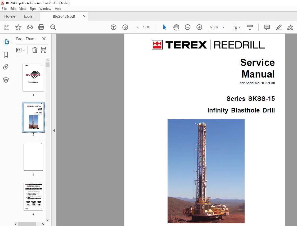
Cat Bucyrus Terex Series SKSS-15 Infinity Blasthole Drill Service Manual SN 1D67C80 – PDF DOWNLOAD
$33.95
Cat Bucyrus Terex Series SKSS-15 Infinity Blasthole Drill Service Manual SN 1D67C80 – PDF DOWNLOAD
Description
Cat Bucyrus Terex Series SKSS-15 Infinity Blasthole Drill Service Manual SN 1D67C80 – PDF DOWNLOAD
FILE DETAILS:
Cat Bucyrus Terex Series SKSS-15 Infinity Blasthole Drill Service Manual SN 1D67C80 – PDF DOWNLOAD
Language : English
Pages : 803
Downloadable : Yes
File Type : PDF
IMAGES PREVIEW OF THE MANUAL:
DESCRIPTION:
Cat Bucyrus Terex Series SKSS-15 Infinity Blasthole Drill Service Manual SN 1D67C80 – PDF DOWNLOAD
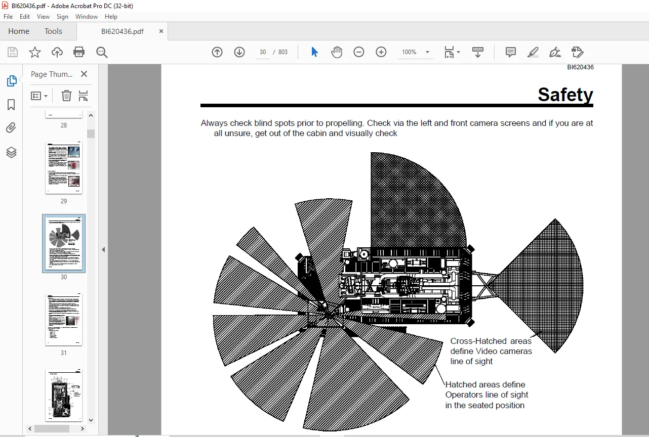
Safety:
- The Rotary Drill is a heavy moving machine with a mast which raises vertically for drilling. Like
all moving objects and reach extending devices, there are potential hazards associated with its
use. These hazards will be minimised if the machine is properly inspected and maintained. The
maintainers must read this manual and have been trained to use the machine in an appropriate and
safe manner. Should any ques- tions arise concerning the maintenance or operation of the machine
contact Reedrill in your state or territory. - There are many personal hazards and dangers associated with working on and around a drill rig. If
the safety instructions outlined in this section are adhered to, risk of injury or harm to yourself
and others will be significantly reduced.
BEFORE OPERATION:
* Wear all mandatory (ie safety helmet, eye protection, hearing protection) and other necessary Personal Protective Equipment when operating or working on or in the vicinity of the machine.
* Be sure all safety guards, hand rails and access steps or ladders are securely in place and in good condition.
* Always maintain three-point contact when mounting and dismounting the machine and never attempt to carry tools or equipment when getting on the machine. Place equipment on the drill prior to climbing the access ladders.
* Be sure all connections in compressed air lines are coupled and secured, and that hose socks are in place and secured to prevent accidental disconnection.
* Be sure that all personnel are clear of the machine and work area before starting the engine
or operating the machine.
* Be sure that the drill area is clear of all obstructions before operating the machine
* Ensure that the safety chain is attached when using a towbar
* Do not operate the machine with: a hydraulic leak, broken or damaged electrical wiring or
damaged hydraulic hoses or fittings
* Do not operate the machine without familiarising yourself with the location of all hand held fire extinguishers
* Be sure the fire suppression system has not been activated, is still pressurised, and that lines and nozzles are in the correct place and not damaged
* Do not operate the machine without familiarising yourself with the location of on-board fire
suppression activation points
* Do not operate the machine without first checking that all emergency stops are operational and familiarising yourself as
to their location.
* Do not use the machine for anything other than its designed purpose for blasthole drilling
* Do not wear jewellery or loose fitting clothing when working on the machine. Keep clothing and
hands clear of moving parts
* Do not move the machine if the drill is in a potentially unstable position
* Always be aware of the drill rigs automated functions and make sure people are clear of all
components. The Rotary Drill has an automated function of the dust curtain raise/lower cylinders
when the machine is switched from “Drill” to “Pro- pel” mode
* Do not propel the machine with the mast raised over undulat- ing ground or across grades or
over any distance other than short distances on a drill pattern.
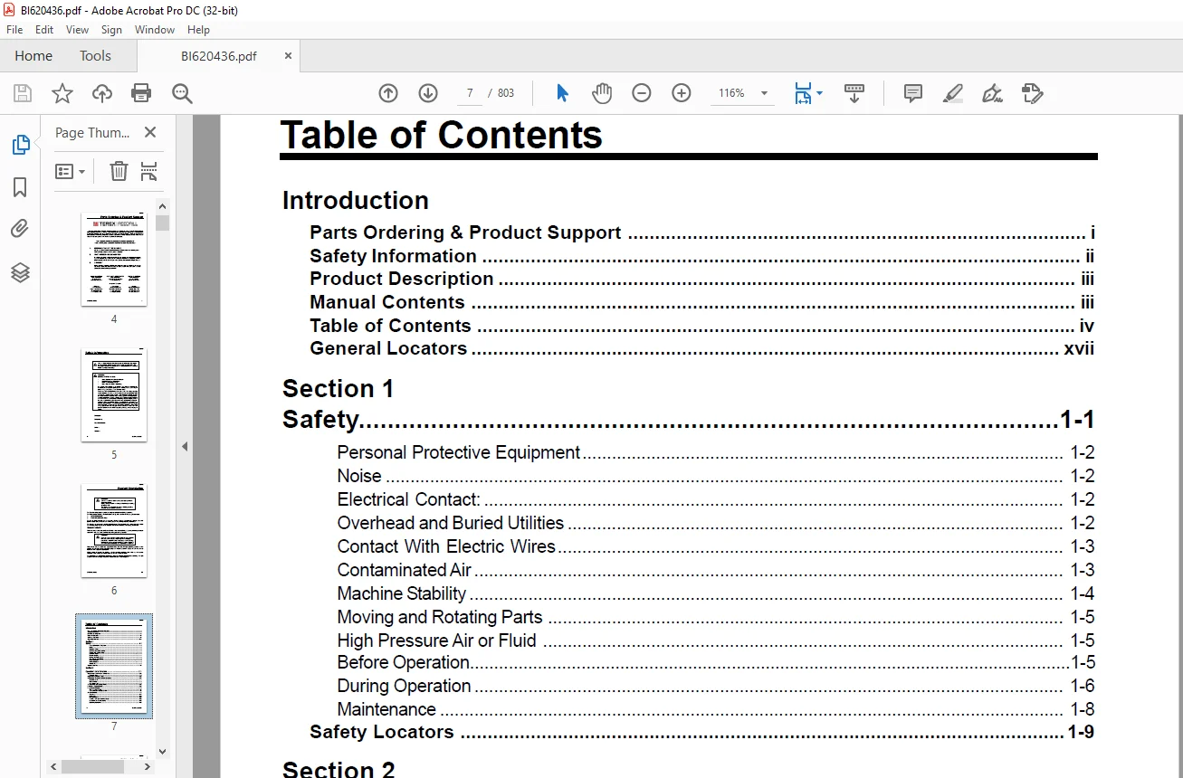
TABLE OF CONTENTS:
Cat Bucyrus Terex Series SKSS-15 Infinity Blasthole Drill Service Manual SN 1D67C80 – PDF DOWNLOAD
Introduction
Parts Ordering & Product Support i
Safety Information ii
Product Description iii
Manual Contents iii
Table of Contents iv
General Locators xvii
Section 1
Safety 1-1
Personal Protective Equipment 1-2
Noise 1-2
Electrical Contact: 1-2
Overhead and Buried Utilities 1-2
Contact With Electric Wires 1-3
Contaminated Air 1-3
Machine Stability 1-4
Moving and Rotating Parts 1-5
High Pressure Air or Fluid 1-5
Before Operation 1-5
During Operation 1-6
Maintenance 1-8
Safety Locators 1-9
Section 2
Operator’s Cab/ Controls 2-1
Operator’s Controls and Indicators 2-2
Control Panels 2-2
Right Hand Control Panel 2-3
Instrument Panel and Circuit Breakers 2-4
Circuit Breakers 2-4
Light Switches 2-5
Instrument Panel 2-5
System Pressure Guage Panel 2-6
Left Hand Control Panel 2-8
Foot Control Pedals 2-14
Thread Grease Switch 14
Pipe Safety Arm Override Switch 14
Air Conditioner 15
Contents 2-17
Introduction 2-19
Unit Specification 2-20
Technical Data and Control Settings 2-23
Installation and Commissioning 2-25
Operating Instructions 2-32
BI620436
SKSS Introduction v
Table of Contents
Routine Maintenance Procedures 2-34
Fault Diagnosis 2-38
Warranty 2-48
Basic Spare Parts Listing 2-49
Reference Drawings 2-51
Section 3
Main Frame – Crawlers 3-1
Main Frame Repair 3-2
Leveling Jacks 3-3
Leveling Jack Cylinders 3-4
Remove 3-4
Replace 3-4
Mast Elevating Cylinders 3-5
Remove 3-7
Replace 3-7
Crawler Assembly 3-8
Crawler Component Repair 3-9
Metric Bolt Torque Specifications 3-10
Track Maintenance 3-11
Before Operating Machine: 3-11
General Maintenance 3-11
Track Tension Adjustment 3-12
Hydraulic Tensioner 3-13
Correct Track Tension 3-13
Description 3-14
Nitrogen Tensioner 3-15
Hydraulic Tensioner 3-16
Repair 3-16
Nitrogen Tensioner Assembly 3-17
Track Tension Adjustment 3-18
Nitrogen Tensioner – Filling Instructions 3-18
Nitrogen Tensioner – Pressure Check 3-20
Nitrogen Tensioner – Pressure Release 3-20
Track Chain – Separate 3-22
Track Chain Repair 3-24
Track Link – Repair & Replace 3-24
Track Link – Description 3-25
Track Shoes Installation 3-26
Track Link Position 3-26
Track Shoe – Mounting to Track Chain 3-26
Direct Torque Method 3-27
Torque Turn Method 3-27
Track Shoe – Retightening 3-27
Track Shoe Bolt Torque (Direct Torque Method) 3-28
Track Shoe Bolt Torque (Torque Turn Method) 3-29
BI620436
vi SKSS Introduction
Table of Contents
Track Chain and Shoe Installation 3-30
Track Chain with Shoes 3-30
Track Chain & Shoe – Assembly & Installation 3-30
Final Drive 3-32
Final Drive – General Description 3-32
Final Drive Unit Removal 3-33
Removal from Track Frame 3-33
Installation into Track Frame 3-34
Final Drive Maintenance 3-35
Oil Check / Change 3-35
Final Drive Oil 3-36
Specifications 3-36
Recommended Oil 3-36
Final Drive Assembly 3-37
Parking Brake – Description 3-38
Final Drive Disconnect 3-39
Final Drive – Disconnect & Parking Brake 3-40
Towing Procedure – Gear Drive Disconnect 3-40
Parking Brake – Removal & Installation 3-40
Idler Assembly 3-41
Idler Unit Removal 3-43
Idler Unit – Assembly 3-45
Track and Support Rollers 3-49
General Description 3-49
Track Roller – Removal & Disassembly 3-51
Support Roller – Removal & Disassembly 3-52
Track and Support Roller – Assembly 3-53
Track and Support Roller – Test and Install 3-54
Auxiliary Crane 3-56
Hiab Hydraulic Crane 3-56
Load Lift Capacities 3-56
Maintenance 3-57
Fuel Tank Fill Assembly 3-58
Hydraflo Fuel Fill 3-58
Troubleshooting 3-59
Section 4
Engine / Drive Train / Compressor 4-1
Power Group Locator 4-2
Engine 4-3
Engine Fuel System 4-4
Oil Reserve Systems 4-12
Engine Oil Reserve System Circuit 4-12
Engine Oil Reserve System 4-12
LED Monitor Readings 4-13
Signals 4-13
Adjustment of Running Oil Level 4-13
BI620436
SKSS Introduction vii
Table of Contents
Wiring Diagram 4-14
Oil Pressure Switch 4-14
Servicing 4-14
Troubleshooting 4-15
Oil Reserves Systems – Maintenance 4-15
Engine and Compressor Air Cleaners 4-16
Engine and Compressor Air Cleaner Service 4-17
Inspection and General Service 4-17
Engine and Compressor Air Cleaner Service 4-18
Safety Element Service 4-19
Flexible Drive Coupling Service 4-20
Adaptor Flanges 4-20
Centering Flanges 4-20
Rubber Element 4-20
Tube Assembly 4-20
Mounting Screws and Adhesive 4-21
Pump Drive 4-23
Pump Identification 4-23
Pump Drive Assembly – Removal and Replacement 4-24
Pump Drive Gearbox 4-25
Pump Drive Gearbox – Repair 4-26
3″ Input Shaft Assembly 4-28
Hydraulic Pumps 4-29
Compressor Installation 4-30
Compressor Drive Coupling-Removal and Replacement 4-31
Compressor Unit – Installation 4-32
Before Start-Up of New or Rebuilt Compressor: 4-34
Drill Compressor 4-35
High Pressure Compressor 4-36
Section 1 Safety 4-36
General 4-36
Pressure Release 4-36
Fire and Explosion 4-37
Moving Parts 4-37
Toxic and Irritating Substances 4-37
Electrical Shock 4-38
Lifting 4-38
Section 2 Description 4-39
Introduction 4-39
Compressed Air Functions 4-39
Sullair Compressor Unit 4-40
Compressor Discharge System 4-41
Compressor Cooling and Lubrication System 4-42
Compressor Fluid Circuit 4-43
Compressor Condensation Table 4-46
Compressor Air Circuit 1475cfm @ 500psi 4-47
Compressor Air Circuit 4-48
Compressor Functional Description 4-61
Air Inlet System 4-61
BI620436
viii SKSS Introduction
Table of Contents
Lubrication Guide 4-61
Application Guide 4-61
Capacity Control System With Poppet Valve, Functional Description 4-62
Start Mode 4-62
Normal Operation 4-62
Modulating Mode 4-62
Unload Mode 4-62
Shutdown Mode 4-63
Instrument Group 4-63
Protection System 4-63
Compressor Operation 4-64
Section 3 Operation 4-64
General 4-64
Purpose Of Controls 4-64
Initial Start-up Procedure 4-66
Subsequent Start-up Procedure 4-67
Shutdown Procedure 4-67
General Operating Instructions 4-67
Compressor Maintenance 4-68
Section 4 General Maintenance 4-68
General 4-68
Daily Operation 4-68
Maintenance After Initial 50 Hours Of Operation 4-69
Maintenance Every 250 Hours 4-69
Maintenance Every 500 Hours 4-69
Maintenance Every 1000 Hours 4-69
Main Drive Shaft Seal Replacement 4-70
Interstage Tube 4-73
Discharge Check Valve 4-74
Separator/Receiver Tank 4-75
Minimum Pressure / Check Valve 4-77
Scavenge Line 4-78
Scavenge Line Sight Glass 4-78
Scavenge Line Oriface 4-78
Compressor Discharge Temperature Switches, Senders and Gauges 4-79
Thermal/Bypass Valve 4-80
Fluid Stop Valve 4-82
Compressor Fluid Filter 4-84
Inlet Valve 4-86
Compressor Regulation 4-88
Relieving Regulators 4-88
Reducing Regulators 4-91
System Blowdown Valve 4-93
Running Blowdown Valve 4-94
Moisture Separator Maintenance 4-96
Auxiliary Regulator 4-97
Troubleshooting 4-101
Compressor Oil Cooler Assembly 4-105
Compressor oil cooler 4-105
BI620436
SKSS Introduction ix
Table of Contents
Radiator/Hydraulic Oil Cooler Assembly 4-106
Radiator/Oil Cooler Repair 4-107
High Pressure Compressor Fluid Cooler 4-109
Radiator Cooler 4-117
Section 5
Dust Control Systems 5-1
Water Injection 5-3
Water Tanks 5-3
Water Tank Top-up Solenoid Valve 5-4
Water Injection Relief Valve 5-6
Water Injection Control 5-7
Basic Water Injection System – SKSS-15 5-9
Water Pump 5-10
Pump Specifications 5-10
Servicing Instructions 5-10
Parts List 5-11
Recommended Lubricants 5-16
Water Injection Valve 5-17
Water Injection Ball Valve Assembly 5-17
Water Injection Ball Valve 5-17
Actuator 5-18
High Pressure Cleaner 5-31
Foam Injection 5-37
Section 6
Mast / Rotary Drive / Pipe Rack 6-1
Mast Weldment 6-2
Mast Repair 6-2
Mast Assembly 6-3
Mast Pivot 6-4
Feed Cylinders 6-5
Feed Cylinder – Removal 6-7
Feed Cylinder Assembly 6-9
Repair 6-10
Installation 6-10
Hoist/Pulldown Cable Adjustment 6-11
Hoist/Pulldown Cable Replacement 6-14
Rotary Drive Assembly 6-16
Rotary Head Guide Alignment 6-17
Rotary Head Drive System 6-18
Rotary Drive – Removal from Mast 6-19
Rotary Drive – Installation 6-19
Rotary Drive Gearbox 6-20
Rotary Drive Gearbox – Item Listing 6-21
Rotary Head Bull Shaft Bearing Nut 6-21
BI620436
x SKSS Introduction
Table of Contents
Rotary Drive Gearbox – Repair 6-22
Main Shaft Bearing Preload 6-22
Air Swivel 6-23
Winch Assembly 6-24
Precautions on the Use of Winches 6-24
Wire Rope 6-24
Wedge Sockets 6-26
Grooved Drums 6-27
Plain (Smooth) Drums 6-27
Drums – Multiple Layers 6-27
Winch Assembly Service Manual 6-28
Hydraulic Winch Repair 6-29
Deck Wrench 6-60
H O B O Wrench 6-61
Breakout System – HOBO 6-62
Pipe Safety Arm 6-62
Pipe Positioner 6-63
Carousel Pipe Rack 6-64
Major Components 6-64
Carousal Indexing 6-65
Pipe Rack Bearings – Removal 6-67
Pipe Rack Components – Inspection 6-70
Pipe Rack – Assembly and Installation 6-71
Pipe Rack Roller – Remove and Replace 6-72
Pipe Rack Roller – Disassembly and Assembly 6-73
Section 7
Hydraulic Systems 7-1
Hydraulic Symbols 7-2
Pressure Setting Sequence 7-4
Hydraulic Tank 7-6
Return Hydraulic Filters 7-7
Main Return and Case Drain Filter 7-8
Main Hydraulic Pumps 7-10
Pump Identification 7-10
Right Track, Left Track/Rotation Pumps 7-11
Hydraulic Piston Pumps Removal and Repair 7-11
Hydraulic Piston Pumps – Operation Specifications Adjustment and Repair 7-11
HD/D Control 7-12
Technical Data 7-14
Port Locations 7-18
Setting Procedure 7-19
Charge Pressure, High Pressure and P O R Relief Settings 7-20
Set Charge Pressure 7-20
Set Crossover Relief (High Pressure) 7-21
Set Pressure Override (P O R ) 7-22
Mechanical Zero Position – HD Pump Control 7-23
BI620436
SKSS Introduction xi
Table of Contents
Hydraulic Zero Position – HD Pump Control 7-24
Removal and Inspection of Charge Pump 7-25
Removal and Installation of Shaft Seal 7-26
Routine Maintenance 7-27
Charge Filter 7-30
Routine Maintenance 7-30
Tram/Rotation Pump Circuit 7-32
Tram/Rotation Pump Circuit 7-33
Rotation Circuit 7-34
Rotary Torque Control 7-34
Rotary Torque Control Circuit 7-36
Rotation/Tram Motor Circuit 7-37
Loop Filters 7-38
Rotary Drive Gearbox Motor 7-42
Rotary Drive Gearbox Motor – Test and Repair 7-42
Case leakage bypass test 7-42
Shaft Seal Replacement 7-43
Trouble Shooting 7-45
Feed and Auxiliary Pump Circuit 7-47
Hydraulic Piston Pumps Removal and Replacement 7-47
Hydraulic Piston Pumps – Operation, Specifications, Adjustment and Repair 7-47
Feed & Auxiliary Functions Pump 7-50
Function of Load Sensing Control (DRS) 7-50
Adjustment Procedure 7-50
Standby Pressure: 7-50
Main Pressure: 7-50
Repair Instructions – Shaft Seal 7-51
Pump Replacement Start Up 7-52
Auxiliary and Feed Circuits 7-53
Main Control Valves 7-54
Valve Stand Assembly 7-54
MP18 Valve – Jack and Mast Raise Valve 7-55
MP22 Valve – Hoist and Pulldown Control 7-57
4WE6 – Aux Functions and Mast Valves 7-60
Exploded View of 4WE6 7-63
Counterbalance Valve 7-64
Counterbalance Valve Adjustments 7-64
Pilot Control Manifold 7-65
Control Valve Assembly 7-67
Auxiliary Pump Load Solenoid Valve – V03 7-67
Shuttle Valve – V04 7-67
Auxiliary Pump Load Sense Relief – V05 7-67
Jacks/Mast raise Load Sense relief – V06 7-68
Drill/Tram Interlock Solenoid Valve – V07 7-68
Drill/Tram Solenoid Valve – V08 7-69
Auto Pulldown Solenoid Valve – V09 7-69
Pilot Operated Directional Valve – V10 7-69
Set-up Interlock Solenoid Valve – V11 7-69
BI620436
xii SKSS Introduction
Table of Contents
Auto Pulldown Pressure Reducing Valve – V12 7-70
Shuttle Valve – V13 7-70
Surge Protection Relief Valve – V14 7-70
Maximum Pulldown Pressure Relief – V15 7-71
2nd Maximum Pulldown Relief Valve – V16 7-71
Reduced Pulldown Relief Valve – V17 7-71
Reduced Pulldown Solenoid Valve – V18 7-71
Shuttle Valve – V19 7-72
Orifice – V20 7-72
Maximum Rotation Pressure Relief – V21 7-72
Surge Protection Pressure Reducing/Relieving Valve – V22 7-72
Feed Valve Assembly 7-73
Hoist/Pulldown Control Valve 410665 MP22 7-73
Set Max Pulldown Relief Valve (V15) 7-73
Feed Control Valve 7-61
Hydraulic Feed Circuit 7-76
Holdback Control 7-81
Jack Control and Mast Elevating Circuit 7-82
Pressure Adjustment 7-83
Leveling Jack Cylinders 7-84
Jack Leg Cylinder 7-84
Counterbalance Valve Test Procedure 7-85
Mast Elevating Cylinders 7-86
Counterbalance Valve Test Procedure 7-87
Auxiliary Functions Circuit 7-88
Hydraulic Operated Breakout Wrench 7-90
Setting of HOBO Sequence Valves 7-91
Pipe Positioner Sequence Valves 7-92
Setting of Pipe Positioner Sequence Valves 7-92
Pipe Safety Arm Sequence Valves 7-93
Setting of Pipe Safety Arm Sequence Valves 7-93
Hydraulic Gear Pumps 7-94
Hydraulic Gear Pumps – Repairs Operation Specifications and Adjustment 7-94
Shaft Seal Removal and Replacement 7-95
Cooler Fan Circuit 7-97
Fan Motor Circuit 7-97
Adjustment 7-97
Cooler Fan Motor 7-100
Hydraulic Thermostatic Valve 7-104
Central Lube 7-105
Hydraulic Circuit 7-106
Air Conditioner Compressor Drive Circuit 7-107
Air Conditioner Drive Motor 7-108
Water Injection Circuit 7-112
Water Injection valve 7-113
Water Injection Electrical Circuit 7-114
Toc-2 Controller 7-114
Water Injection Valve 7-115
BI620436
SKSS Introduction xiii
Table of Contents
Water Pump Motor 7-132
Shaft Seal Repair 7-133
Hydraulic Cylinders Repair 7-136
Hydraulic Cylinders List 7-136
Section 8
Vigilante Guide and Electrical Components 8-1
Electrical Locator 8-2
Batteries 8-5
Jump Starting 8-6
Welding Precautions 8-8
Vigilante Guide 8-9
Contents 8-9
Important Information 8-10
PLC 8-11
Run/Rem/Program Key-switch 8-11
Eeprom 8-12
Recover From A Processor Fault 8-12
Output Card 8-13
Replacing A Faulty Card 8-13
Analog Card Configuration 8-13
Touchscreen 8-14
Setting The Date and Time 8-14
Changing A CF Card 8-14
Setting Brightness 8-14
Laser Depth System 8-15
General Info 8-15
Functional Description of Operation 8-15
Setting up the Laser 8-15
Safety Instructions & Precautions 8-16
Calibration 8-16
Pipe in Hole Detection (option) 8-17
Pipe Rack Swing Interlock 8-17
Distance Meter 8-17
Setting Up 8-17
Start Up and Shut Down 8-18
Idle Timer 8-18
Hydraulic Function Enable 8-18
Drill Tram Enable Function 8-18
Alarms 8-18
Shutdown Alarms 8-18
Indication Only Alarms 8-19
Filter Bypass Indication Only Alarms 8-19
Solenoid Control 8-19
Drill / Tram Solenoid (Off to Tram / On to Drill) 8-19
Drill / Tram Interlock Solenoid (On to Tram / On to Drill) 8-19
Tram Conditions OK 8-20
BI620436
xiv SKSS Introduction
Table of Contents
Drill Conditions 8-20
Setup Interlock Solenoid (On to operate Jacks and Mast) 8-21
Pipe Rack Pressure Reduce Solenoid (On to reduce pull-down pressure) 8-21
Aux Priority Solenoid (On to load Aux pressure) 8-21
Pipe Rack Swing In interlock 8-21
Dust Curtain Raise Solenoid 8-21
Pipe Positioner Kickout Solenoid 8-21
Washdown Solenoid 8-22
Auto Lube 8-22
Operation 8-22
Hammer Oiler System 8-22
Auto Mode 8-22
Manual Mode 8-22
Gauges 8-23
General Info 8-23
Operation checks 8-23
Pressure Transducer 8-23
Level Transducer 8-23
Hammer Oil Level Transducer 8-23
Temperature Transducer 8-24
Water Flow Transducer 8-24
Inclinometers 8-25
Head Speed Module 8-28
General info 8-28
Calibrating 8-28
Level Switches 8-29
Dust Suppression 8-29
Water Injection 8-29
Turkey Spray 8-29
Water Suppression Tank – Top Up 8-29
Head Speed Module 8-31
Inclinometer 8-33
Ladder Prox Switch 8-36
Laser 8-37
Level Switches 8-49
Radiator Level Switch 8-53
Level Transducers 8-57
Hammer Oil Level Transducer 8-67
Pressure Transducers 8-69
Temperature Transducer 8-78
Temperature Sensor 8-90
Water Flow Transducer 8-91
Water Control Module 8-105
Rod Counter Prox Switch 8-112
Remote Fuel Level Display 8-113
BI620436
SKSS Introduction xv
Table of Contents
Section 9
Lubrication and Preventive Maintenance 9-1
Central Lube System 9-2
Hydraulic Control Schematic 9-3
Auto Lube 9-3
Central Lube System Circuit Drawing 9-5
Central Lube Tank Assembly 9-6
Central Lube System 9-7
Central Lube Pump Module 9-8
Central Lube Pump 9-21
SL-1 Injector Assembly 9-46
SL-1 Injector Specifications 9-46
Hammer Oiler Tank Assembly 9-48
Hammer Oil Circuit 9-49
Hammer Oil System 9-50
Air Service Unit Components 9-50
Filter Regulator 9-51
Air Line Oiler 9-52
Pipe Thread Lubricator 9-70
Air Service Unit 9-70
Filter Regulator 9-71
Air Line Lubricator 9-72
Pipe Thread Pump 9-73
Filter Locator 9-81
Lubrication And Maintenance 9-83
Safety 9-83
Track Gear 9-83
Engine Maintenance 9-84
Air Cleaners 9-85
Air Filter Elements 9-85
Alternator Maintenance 9-85
Pump Drive And Drive Shaft Maintenance 9-86
Compressor Maintenance 9-86
Cooler Packs 9-87
A-Frame And Pivot Point Maintenance 9-87
Pull Down And Hoist Ropes And Sheaves Maintenance 9-88
Rotary Head Maintenance 9-88
Hydraulic System Maintenance 9-89
Hydraulic Maintenance 9-89
Water Pump Maintenance 9-90
Cab Maintenance 9-90
Air Conditioner Maintenance 9-90
Battery Maintenance 9-91
BI620436
xvi SKSS Introduction
Lubrication System Maintenance 9-91
Fire Suppression Maintenance 9-91
Lubrication – General 9-92
Equipment Lubrication 9-92
Lubrication & Maintenance Chart – 250hr 9-93
Lubrication & Maintenance Chart – 500hr 9-103
Lubrication & Maintenance Chart – 1000hr 9-114
Lubrication & Maintenance Chart – 2000hr 9-125
Lubrication and Maintenance 9-137
Lubricant Specifications 9-138
Hydraulic System 9-138
Hydraulic Tank Capacity 9-138
Compressor Lubrication 9-139
Lubricating Grease 9-140
Gear Lubricant 9-140
Scheduled Oil Sampling Analysis 9-140
Torque Values for Split Flange Connections 9-141
Torque Values for Hydraulic Tubes & Fittings 9-142
Torque Values for Standard Fasteners 9-143
Need help? Contact: [email protected]
https://vimeo.com/867083692?share=copy
PLEASE NOTE:
- This is the same manual used by the DEALERSHIPS to SERVICE your vehicle.
- The manual can be all yours – Once payment is complete, you will be taken to the download page from where you can download the manual. All in 2-5 minutes time!!
- Need any other service / repair / parts manual, please feel free to contact us at heydownloadss @gmail.com . We may surprise you with a nice offer
S.V