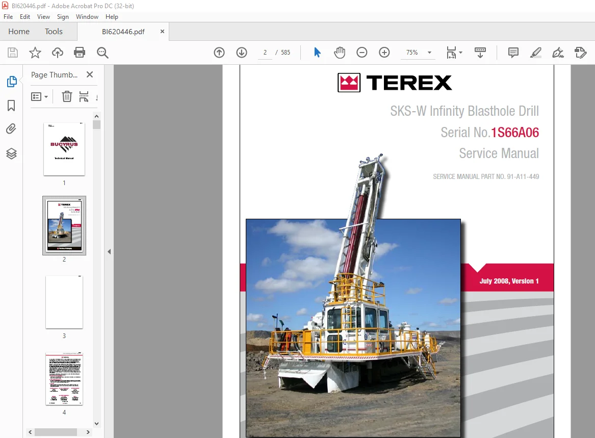
Cat Bucyrus Terex SKS-W Infinity Blasthole Drill Service Manual SN 1S66A06 – PDF DOWNLOAD
$28.95
Cat Bucyrus Terex SKS-W Infinity Blasthole Drill Service Manual SN 1S66A06 – PDF DOWNLOAD
Description
Cat Bucyrus Terex SKS-W Infinity Blasthole Drill Service Manual SN 1S66A06 – PDF DOWNLOAD
FILE DETAILS:
Cat Bucyrus Terex SKS-W Infinity Blasthole Drill Service Manual SN 1S66A06 – PDF DOWNLOAD
Language : English
Pages : 585
Downloadable : Yes
File Type : PDF
IMAGES PREVIEW OF THE MANUAL:
DESCRIPTION:
Cat Bucyrus Terex SKS-W Infinity Blasthole Drill Service Manual SN 1S66A06 – PDF DOWNLOAD
Safety Information:
- This manual is furnished with your Infinity Series rotary blasthole drill to aid you in performing
the necessary service work to maintain your drill in good operating condition. - This manual contains repair and adjustment information for all major operating systems on the
machine. In some cases such as hydraulic pumps and motors it is better to replace the unit with a
new or rebuilt unit than to perform major repairs. Should further information be desired or should
particular problems arise which are not covered sufficiently in this manual, the matter should be
referred to manufacturer. - The descriptions and specifications contained in this manual were in effect at the time of printing.
The right is reserved to make changes at any time without notice and without obligation. - It is YOUR responsibility to understand and follow manufacturer’s instructions on machine operation
and service, and to observe pertinent safety precautions, laws and regulations. Failure to read and
understand this manual and all safety, capacity and instruction placards on the machine before
operating the unit, constitutes a misuse of the machine. - It is your responsibility to know the
manufacturer’s specific requirements, government regulations, required precautions and any work
hazards which may exist. You must make these known to all personnel working with the equipment or
in the area, so that all may take the necessary and required safety precautions. Keep all children,
visitors, and untrained personnel away from the equipment. - It is also your responsibility to
operate your equipment with skill, good judgment, and caution. Following recognised safety
procedures will help you avoid accidents. Failure to heed these instructions can result in property
damage, serious injury or death.
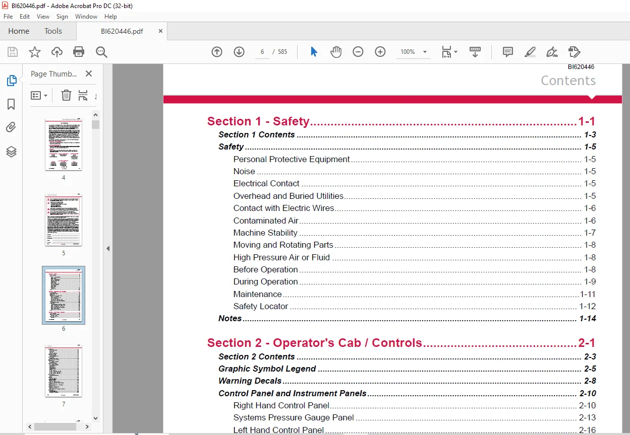
TABLE OF CONTENTS:
Cat Bucyrus Terex SKS-W Infinity Blasthole Drill Service Manual SN 1S66A06 – PDF DOWNLOAD
Section 1 – Safety 1-1
Section 1 Contents 1-3
Safety 1-5
Personal Protective Equipment 1-5
Noise 1-5
Electrical Contact 1-5
Overhead and Buried Utilities 1-5
Contact with Electric Wires 1-6
Contaminated Air 1-6
Machine Stability 1-7
Moving and Rotating Parts 1-8
High Pressure Air or Fluid 1-8
Before Operation 1-8
During Operation 1-9
Maintenance 1-11
Safety Locator 1-12
Notes 1-14
Section 2 – Operator’s Cab / Controls 2-1
Section 2 Contents 2-3
Graphic Symbol Legend 2-5
Warning Decals 2-8
Control Panel and Instrument Panels 2-10
Right Hand Control Panel 2-10
Systems Pressure Gauge Panel 2-13
Left Hand Control Panel 2-16
Circuit Breaker and Instrument Panels 2-20
Engine Gauges, Switches and Indicator Lights 2-21
Cab Heater 2-22
Cab Heater Fault Isolation 2-22
Air Conditioner 2-23
T7 Series Split System Air Conditioning Manual 2-23
Section 1 0 Technical Data and Control Settings 2-24
Section 2 0 Installation and Commissioning 2-26
Section 3 0 Routine Maintenance Procedures 2-32
Section 4 0 Fault Diagnosis 2-33
Section 5 0 Reference Drawings 2-42
Notes 2-47
Section 3 – Main Frame / Crawlers 3-1
Section 3 Contents 3-3
Main Frame Repair – General 3-5
Main Frame Repair 3-5
Weld Inspection Schedule 3-6
Main Frame 3-6
BI620446
Int-6 SKS-W Introduction
Contents
Levelling Jacks 3-7
Levelling Jacks Cylinder 3-7
Levelling Jacks 3-8
Limit Switch 3-8
Levelling Jack Cylinders 3-8
Mast Elevating Cylinders 3-9
Mast Elevating Cylinders 3-9
Internal Counterbalance Valve 3-10
Crawler Assembly 3-12
Parts List 3-13
Crawler Component Repair 3-13
Metric Bolt Torque Specifications 3-14
Track Maintenance 3-15
Before Operating the Machine 3-15
General Maintenance 3-15
Track Tension Adjustment 3-16
Before Operating the Machine 3-16
General Maintenance 3-16
Track Assembly 3-17
Idler Unit Description 3-18
Hydraulic Tensioner 3-19
Repair 3-19
Nitrogen Tensioner 3-20
Nitrogen Tensioner – Filling Instructions 3-21
Nitrogen Tensioner – Pressure Check 3-22
Nitrogen Tensioner – Pressure Release 3-22
Hydraulic Tensioner 3-23
Hydraulic Tensioner Assembly 3-23
Repair 3-23
Track Chain 3-24
Track Chain – Separate 3-24
Track Chain Repair 3-25
Track Shoes Installation 3-27
Track Link Position 3-27
Track Shoe – Mounting to Track Chain 3-27
Track Shoe Bolt Torque (Direct Torque Method) 3-29
Bolt Torque KN111 3-29
Track Shoe Bolt Torque (Torque Turn Method) 3-30
Bolt Torque KN111 3-30
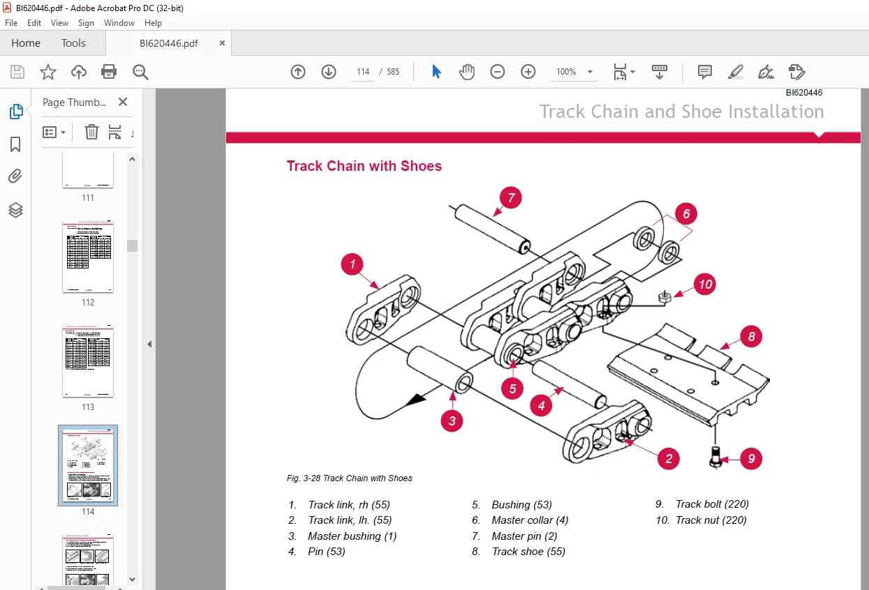
Track Chain and Shoe Installation 3-31
Track Chain with Shoes 3-31
Track Chain and Shoe – Assembly and Installation 3-31
Final Drive Unit 3-33
General Description 3-33
Removal from Track Frame 3-34
Installation into Track Frame 3-35
BI620446
SKS-W Introduction Int-7
Contents
Final Drive Maintenance 3-36
Final Drive Oil 3-37
Final Drive Assembly 3-38
Parts List 3-39
Final Drive – Disconnect and Parking Brake 3-40
Towing Procedure – Gear Drive Disconnect 3-40
Parking Brake – Description 3-41
Parking Brake – Removal and Installation 3-41
Idler Unit 3-42
Idler Unit – Assembly 3-42
Idler Unit – Removal 3-45
Track and Support Rollers 3-46
Track Roller Assembly 3-46
General Description 3-46
Track Roller – Removal and Disassembly 3-47
Support Roller – Removal and Disassembly 3-47
Track and Support Roller – Assembly 3-48
Track and Support Roller – Test and Install 3-49
Track and Sprocket Inspection 3-51
Track Inspection and Wear Limit Guide 3-51
Sprocket Wear Patterns 3-55
Auxiliary Crane 3-61
Rear Deck Crane Palfinger Crane PC 1300 Service Information 3-61
Warranty Provisions 3-62
Checking Bolted Connections 3-62
Maintenance Chart 3-63
Lubrication 3-65
Hydraulic Fluids 3-68
Oil Change / Oil Maintenance 3-69
Cleaning Agents and Equipment 3-70
Repairing Paint Damage 3-71
Removal From Service and Disposal 3-71
Notes 3-72
Section 4 – Engine / Drive Train / Compressor 4-1
Section 4 Contents 4-3
Power Group Locator 4-5
Caterpillar C27 Engine 4-6
Caterpillar C27 Engine 4-6
Engine Mounts 4-7
Engine and Compressor Air Cleaner 4-8
Engine and Compressor Air Cleaner Service Assembly 4-8
Engine and Compressor Air Cleaner Service 4-9
Flexible Drive Coupling 4-12
Flexible Drive Coupling Service 4-12
BI620446
Int-8 SKS-W Introduction
Contents
Pump Drive 4-14
Pump Identification and Parts List 4-14
Pump Drive Assembly – Removal and Replacement 4-15
Pump Drive Gearbox 4-16
Pump Drive Gearbox 4-16
Pump Drive Gearbox Repair 4-17
Pump Drive Gear Box Input Shaft Assembly 4-18
Hydraulic Pumps 4-20
Hydraulic Pumps – Removal and Replacement 4-20
Compressor Installation 4-21
Safety 4-21
Compressor Installation 4-24
Compressor Drive Coupling 4-26
Compressor Alignment 4-27
Compressor Shaft Seal 4-28
Compressor Shaft Seal 4-28
Low Pressure Compressor 4-30
Description 4-30
Compressed Air Functions 4-30
Inlet Valve 4-34
Compressor Regulation 4-36
Compressor Regulation Closed Poppet Inlet 4-37
Running Blowdown Valves 4-38
Relieving Regulators 4-39
Compressor Control Set-up Closed Poppets Inlet 4-41
Compressor Functional Description 4-50
Compressor Operation 4-51
Compressor Operation 4-51
Compressor Maintenance 4-53
General Maintenance 4-53
Compressor Receiver Tank Assembly 4-54
Parts List 4-55
Separator Elements 4-56
Separator Elements – Remove and Replace 4-57
Scavenge Line 4-58
Compressor Discharge Temperature Gauge, Switch and Sender 4-60
Minimum Pressure Valve 4-61
Minimum Pressure / Check Valve Maintenance 4-61
Thermal Bypass Valve 4-62
Thermal Bypass Valve Maintenance 4-63
Compressor Fluid Filter 4-64
Changing Filter Elements 4-65
Troubleshooting 4-66
Coolers 4-68
Hydraulic Oil / Hydraulic Cooler Assembly 4-68
Compressor Oil Cooler 4-69
Fan Speed 4-69
BI620446
SKS-W Introduction Int-9
Contents
Aluminium Tube Air to Oil Cooler 4-70
Aluminium Tube Air to Oil Cooler – Standard Parts 4-70
Removal Replacement 4-71
Oil Cooler – Internal Cleaning 4-73
Radiator Cooler 4-75
Typical Radiator Core – Standard Parts 4-75
Cleaning 4-76
Tube Removal 4-76
Seal Installation 4-77
Tube Installation 4-78
Notes 4-80
Section 5 – Dust Control System 5-1
Section 5 Contents 5-3
Dust Control System 5-5
Dust Control Systems 5-5
Dust Collector 5-6
Dust Collector Assembly 5-10
Parts List 5-11
Fan Wheel 5-12
Routine Maintenance 5-13
Water Injection 5-14
Water Tanks 5-14
Water Injection Relief Valve 5-15
Water Injection Control 5-16
Water Injection Basic Circuit 5-18
Water Pump 5-19
Pump Specifications 5-19
Servicing Instructions 5-19
Water Injection Pump and Parts List 5-20
Replacing Piston Cup Seals 5-21
Replacing Suction and Discharge Valves 5-22
Replacing Power End Bearings 5-23
Servicing the Wrist Pin Bearings 5-24
Fastener Torque Requirements 5-24
Recommended Lubricants 5-25
Water Pump Motor Repair 5-25
Water Injection Hydraulic Control Valve Repair 5-25
Water Pump Drive Coupling 5-25
Level and Flow Transducer 5-25
Notes 5-26
Section 6 – Mast / Rotary Drive / Pipe Rack 6-1
Section 6 Contents 6-3
Mast Weldment 6-5
Mast Repair 6-5
BI620446
Int-10 SKS-W Introduction
Contents
Weld Inspection Schedule 6-6
Mast Inspection 6-6
Mast Assembly 6-7
Mast Assembly 10m 6-7
Mast Weldment 6-8
Mast Pivot 6-8
Mast Locking 6-8
Hoist / Pulldown Cylinder 6-9
Hoist / Pulldown Cylinder Parts List 6-9
Removal From Mast Assembly 6-10
Repair 6-11
Installation 6-11
Hoist / Pulldown Cable Adjustment 6-13
Hoist / Pulldown Cable Adjustment 6-13
Hoist / Pulldown Cable Replacement 6-15
Rotary Drive 6-17
Rotary Head Assembly and Parts List 6-17
Rotary Head Guide Alignment 6-18
Rotary Head – Drive System 6-19
Rotary Drive – Removal from Mast 6-20
Rotary Drive – Installation 6-20
Rotary Drive Gearbox – Repair 6-21
Rotary Head Bull Shaft Bearing Nut 6-22
Air Swivel 6-23
Winch Assembly 6-24
Precautions on the use of Winches 6-24
Wire Rope 6-24
Wedge Sockets 6-26
Grooved Drums 6-26
Plain (Smooth) Drums 6-27
Drums – Multiple Layers 6-27
Winch Assembly Service 6-28
BG8A and BG8B Hydraulic Winch Manual 6-29
Forward 6-30
Explanation of Model Number 6-30
Theory of Operation 6-31
Winch Installation 6-33
Wire Rope Installation 6-34
Preventative Maintenance 6-35
071 Motor 6-36
Trouble Shooting 6-37
Disassembly of Winch 6-41
Planetary Carrier Service 6-43
Motor Support Brake Cylinder Service 6-45
Brake Clutch Service 6-49
Winch Assembly 6-51
BI620446
SKS-W Introduction Int-11
Contents
Brake Valve Service 6-53
Reversing Direction of Drum Rotation 6-55
Recommended Fastener Torque 6-56
Metric Conversion Table 6-57
Deck Wrench 6-58
Deck Wrench 6-58
H O B O Wrench 6-59
HOBO Wrench 6-59
Breakout System – H O B O 6-60
Optional Hydraulic Operated Bit Basket – H O B B 6-60
Pipe Positioner 6-61
Pipe Positioner 6-61
Carousel Pipe Rack 6-62
Major Components 6-62
Rod Handling – Carousel Indexing 6-63
Pipe Rack Assembly 6-64
General Information 6-65
Pipe Rack Bearings – Removal 6-65
Pipe Rack Components – Inspection 6-67
Pipe Rack – Assembly and Installation 6-68
Pipe Rack Roller – Remove and Replace 6-69
Pipe Rack Roller – Disassembly and Assembly 6-70
Notes 6-72
Section 7 – Hydraulic Systems 7-1
Section 7 Contents 7-3
Hydraulic Symbols 7-7
Pressure Setting Sequence 7-9
Pressure Setting Sequence 7-9
Hydraulic System 7-9
Hydraulic Tank 7-10
Hydraulic Tank 7-10
Return Hydraulic Filters 7-11
Main Return and Case Drain Filters 7-12
Routine Maintenance 7-13
Changing Filter Elements 7-13
Main Hydraulic Pumps 7-14
Pump Identification and Parts List 7-14
Right Track / Pulldown, Left Track / Rotation Pumps 7-15
Hydraulic Piston Pumps – Removal and Replacement 7-15
Main Pumps 7-16
AA4VG180 Hydraulic Pump EP2 Control 7-16
AA4VG EP Controller 7-18
EP (24V DC) Control 7-19
Technical Data 7-20
Main Hydraulic Pumps 7-21
BI620446
Int-12 SKS-W Introduction
Contents
Setting Procedure 7-22
Port Locations 7-23
Charge Pressure, High Pressure, P O R and Zero Position Settings 7-24
Set Charge Pressure – 450psi (31bar) 7-24
Set Crossover Relief (High Pressure) – 5500psi (380bar) 7-25
Set Pressure Override (P O R) – 5000psi (345bar) 7-26
Set Mechanical Zero Position – EP Pump Control 7-27
Set Hydraulic Zero Position – EP Pump Control 7-28
Removal and Inspection of Charge Pump 7-29
Removal and Installation of Shaft Seal 7-30
Routine Maintenance 7-31
Troubleshooting Procedure 7-32
Charge Circuit 7-34
Charge Circuit 7-34
Charge Filter 7-35
Routine Maintenance 7-35
Changing Filter Elements 7-36
Main Pumps Circuit 7-37
Main Pumps Circuit 7-37
Loop Filters 7-38
Routine Maintenance 7-38
Changing Filter Elements 7-41
Rotation Circuit 7-42
Rotation Circuit 7-42
Rotary Drive Gearbox Motor 7-43
Rotary Drive Gearbox Motor – Test and Repair 7-43
Shaft Seal Replacement 7-44
Troubleshooting 7-46
Tram Circuit 7-48
Tram Circuit 7-48
Main Closed Loop Circuits 7-50
Diverter Valve 7-50
Operation 7-50
Diverter Valve 7-50
Right Track / Pulldown and Hoist Circuit 7-51
Basic Right Track / Pulldown and Hoist Circuit 7-51
Basic Right Track / Pulldown and Hoist 7-51
Pulldown and Hoist Circuit 7-52
Hoist / Pulldown Cylinder Counterbalance Valve 7-52
Left Track / Rotation Pump 7-53
Basic Left Track / Rotation Pump Circuit 7-53
Basic Left Track / Rotation Pump 7-53
Pilot Control Manifold 7-54
Pilot Control Manifold 7-54
Electro Proportional Valves 7-67
Proportional Valve Set-up 7-68
BI620446
SKS-W Introduction Int-13
Contents
Proportional Pulldown 7-69
OEM Controllers / EP Levers 7-70
Auto Pulldown Card 7-71
Auxiliary Pump Circuit 7-72
Auxiliary Pump Circuit 7-72
Spools 7-73
Electro – Hydraulic Kit (24V DC) 7-73
Auxiliary Pump 7-75
Auxiliary Functions 7-75
Auxiliary Pump Operation 7-76
Auxiliary Circuit 7-79
Counterbalance Values 7-81
Counterbalance Valves Adjustment 7-81
Jack Control and Mast Elevating Circuit 7-82
OEM Controllers / EP Levers 7-83
Jack Control and Mast Elevating Control Valve 7-84
Levelling Jack Cylinders 7-85
Jack Leg Cylinder 7-85
Counterbalance Valve Test Procedure 7-86
Mast Elevating Cylinders 7-87
Internal Counterbalance Valve 7-87
Internal Counterbalance Valve Test Procedure 7-88
Hydraulic Operated Breakout Wrench 7-89
H O B O Wrench Circuit Schematic 7-89
H O B O Wrench circuit 7-90
Operation 7-91
Setting of H O B O Sequence Valves 7-92
Cooler Fan Circuit 7-93
Fan Motor Circuit 7-93
Cooler Fan Motor 7-96
Hydraulic Motor 7-96
Hydraulic Thermostatic Valve 7-100
Hydraulic Cooler – Thermal Valve 7-100
Water Injection Circuit 7-101
Dust Collector and Water Injection Circuit 7-101
Water Injection Valve 7-102
Introduction 7-104
Valve Stack Assembly 7-105
Segment Alterations 7-106
Pulsar™ Solenoid Removal and Plug 7-108
Work Port Option Exchange 7-108
Assembly Drawing – VBL By-pass Inlet Segment Parts List 7-110
Assembly Drawing – VPL Work Segment Parts List 7-112
Water Pump Motor 7-114
Water Pump Motor Repair Information 7-114
Shaft Seal Repair 7-115
BI620446
Int-14 SKS-W Introduction
Contents
Hydraulic Cylinder Repair 7-118
Hydraulic Cylinders 7-118
General Information 7-119
H Head 7-121
N Head 7-122
Z Head 7-123
Z Head (Two Piece) 7-124
K Head 7-125
M Head 7-126
Z Piston 7-127
Z Piston (Threaded) 7-128
H and K Piston 7-129
M Piston 7-130
N Piston 7-133
Notes 7-134
Section 8 – Electrical Components 8-1
Section 8 Contents 8-3
Electrical Locator 8-5
Electrical Locator 8-5
Parts List 8-6
Solenoid Banks 8-7
Jump Starting 8-9
Jump Starting 8-9
Batteries 8-11
Batteries 8-11
Welding Precautions 8-12
Welding Precautions 8-12
Vigilante Guide 8-13
Laser Depth System 8-13
Start Up and Shut Down 8-17
Alarms 8-17
Solenoid Control 8-18
Auto Lube 8-20
Gauges 8-20
Level Switches 8-21
Dust Suppression 8-21
N B: For further information on specific electronic components, please refer to
Electronic Components Section on Service Manual CD
Important Information 8-22
PLC 8-23
Touchscreen 8-26
Acknowledgements 8-27
Disclaimers 8-27
Notes 8-28
BI620446
SKS-W Introduction Int-15
Contents
Vendor Documents
• 8 Channel Analog Card • 32 Digital Input Card
• Access Light Timer • Calibrating Laser Depth System
• Hydraulic Flow Meter (optional) • Input and Output Cards
• Iqan-toc • Ladder Prox Switch
• Ldm41a Laser Manual • Level Switch
• Pressure Transducers • Rod Counter Prox Switch
• Remote Level Display • Using a Eeprom
• Water Control Module • Water Flow Transducer
Section 9 – Lubrication and Preventive Maintenance 9-1
Section 9 Contents 9-3
Central Lube System 9-5
Description 9-5
Auto Lube 9-5
Central Lube Tank Assembly 9-6
Auto Lube Licoln Pheumatic Pump Owners Manual 9-7
Central Lube System Circuit 9-17
SL-1 Injectors 9-18
SL-1 Injectors Assembly 9-18
SL-1 Injectors Specifications 9-18
Air Service Units 9-20
Filter Regulator 9-20
Air Line Oiler 9-21
Pipe Thread Lubricator 9-22
Air Service Unit 9-22
Air Operated Pipe Thread Pump 9-23
Filter Locator 9-31
Air Locator Assembly 9-31
Lubrication General 9-32
Equipment Lubrication 9-32
Care of Lubrication Points 9-32
Lubrication and Preventive Maintenance 9-33
Safety 9-33
Track Gear 9-34
Engine Maintenance 9-35
Air Cleaners 9-36
Air Filter Elements 9-36
Alternator Maintenance 9-36
Pump Drive and Drive Shaft Maintenance 9-37
Compressor Maintenance 9-37
Cooler Packs 9-37
A-frame and Pivot Point Maintenance 9-39
Pull Down and Hoist Ropes and Sheaves Maintenance 9-39
Rotary Head Maintenance 9-39
Hydraulic System Maintenance 9-41
BI620446
Int-16 SKS-W Introduction
Contents
Hydraulic Maintenance 9-41
Water Pump Maintenance 9-41
Cab Maintenance 9-41
Air Conditioner Maintenance 9-43
Battery Maintenance 9-43
Lubrication System Maintenance 9-43
Fire Suppression Maintenance 9-43
Weld Inspection Schedule 9-45
Weld Inspection Schedule SK Series 9-45
Lubrication and Maintenance Chart – 250hr 9-46
Lubrication and Maintenance Chart – 500hr 9-55
Lubrication and Maintenance Chart – 1000hr 9-64
Lubrication and Maintenance Chart – 2000hr 9-73
Lubricant Specifications 9-83
Hydraulic System 9-83
Hydraulic Tank Capacity 9-83
Compressor Lubrication 9-84
Compressor Lubricant Specifications 9-84
Lubricating Grease 9-85
Gear Lubricant 9-85
Scheduled Oil Sampling Analysis 9-85
Torque Values for Split Flange Connections 9-86
Torque Values for Split Flange Connections 9-86
Procedure No 1-87 Revision A 9-88
Notes 9-89
Need help? Contact: [email protected]
PLEASE NOTE:
- This is the SAME manual used by the dealers to troubleshoot any faults in your vehicle. This can be yours in 2 minutes after the payment is made.
- Contact us at [email protected] should you have any queries before your purchase or that you need any other service / repair / parts operators manual.
S.V