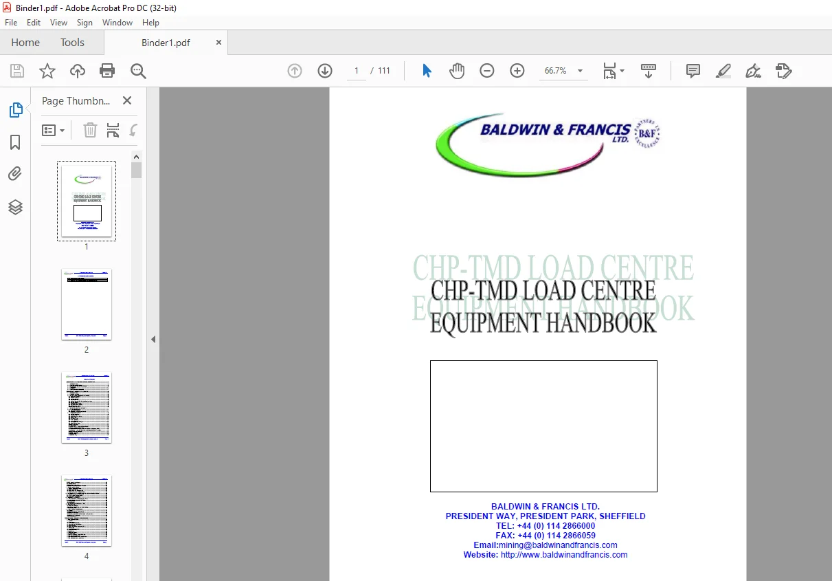
Cat CHP-TMD Load Centre Equipment Operation Handbook Manual – PDF DOWNLOAD
$24.95
Cat CHP-TMD Load Centre Equipment Operation Handbook Manual – PDF DOWNLOAD
Description
Cat CHP-TMD Load Centre Equipment Operation Handbook Manual – PDF DOWNLOAD
FILE DETAILS:
Cat CHP-TMD Load Centre Equipment Operation Handbook Manual – PDF DOWNLOAD
Language : English
Pages : 111
Downloadable : Yes
File Type : PDF
IMAGES PREVIEW OF THE MANUAL:
DESCRIPTION:
Cat CHP-TMD Load Centre Equipment Operation Handbook Manual – PDF DOWNLOAD
1 INTRODUCTION:
This section of the TMD Equipment Handbook gives a general introduction to unit. It is intended to
let the user assess the suitability of the unit for the job in hand. For ease of reference, the
information is given in summary form.
NOTE 1: The TMD series load centres are extremely flexible units and as such have
various build options, some of which are detailed in this section, further options may be listed
in section 8 which details the options fitted to your unit.
NOTE 2: As the basic mechanical and electrical features of the TMD33 and TMD11 units
are very similar, this Handbook will often refer to the units generically as ‘TMD’ for
simplicity.
2 GENERAL DESCRIPTION.
- The Baldwin & Francis TMD Compact Load Centres offer a simple and cost effective solution to the
control of multiple drives underground, up to a supply voltage of 3300 volts. One unit can control
up to 12 drives, up to a total load of 2000 amps; each drive has a full range of protection
features, user-selectable to suit the drive duty as needed. - The TMD contains all major components necessary for the control and protection of
modern underground switchgear; various isolator / circuit breaker combinations, up to twelve
interchangeable drive chassis units, the control system, and auxiliary supplies of both
intrinsically safe and flameproof type. - Flexible control of the TMD’s drives is achieved by the executive controller; this is
a dedicated microprocessor system which acts as the central point of control for the unit. It
drives the ‘switchgear display’ to provide comprehensive monitoring for the control
system. - Each contactor chassis within the TMD is controlled by its own protection and control card mounted
as part of the drive chassis. The protection card houses a micro- computer which
looks after the outgoing cable and motor concerned. - A range of monitoring options is available. The state of each main drive, and all external control
circuits (e.g. motor pilot core, remote start circuit) can be seen instantly on the TMD’s display
panel. ‘User friendly’ messages, in both English and the user’s local language, are
provided to aid the operator and craftsman. - Additionally, external control, monitoring and management systems (e.g. SCADA) can be easily linked
to the TMD. Users can choose a fieldbus-type data transmission (e.g. Modbus/RTU) or an Ethernet
link with either fibre or copper connectivity. - External controls are straightforward; the isolator handles are located on the right-hand side of
the unit. Below these, located on the isolator / transformer compartment door, are switches
controlling the auxiliary supplies. All remaining controls are located on the drive compartment
doors, including keypads for easy access to the switchgear display functions. - AustDAC signals & communications may also be included in the TMD. When fitted this provides a
complete interface to external keys, lockouts and remote monitoring functions.
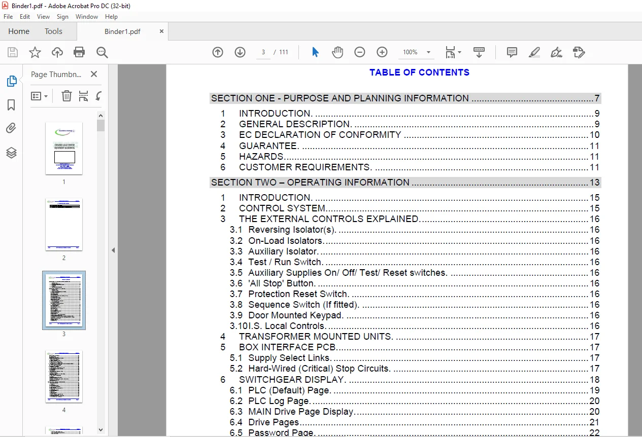
TABLE OF CONTENTS:
Cat CHP-TMD Load Centre Equipment Operation Handbook Manual – PDF DOWNLOAD
SECTION ONE - PURPOSE AND PLANNING INFORMATION......................  7
INTRODUCTION........................................................  9
GENERAL DESCRIPTION.................................................  9
EC DECLARATION OF CONFORMITY........................................ 10
GUARANTEE........................................................... 11
HAZARDS............................................................. 11
CUSTOMER REQUIREMENTS............................................... 11
SECTION TWO – OPERATING INFORMATION................................. 13
INTRODUCTION........................................................ 15
CONTROL SYSTEM...................................................... 15
THE EXTERNAL CONTROLS EXPLAINED..................................... 16
	Reversing Isolator(s)........................................... 16
	On-Load Isolators............................................... 16
	Auxiliary Isolator.............................................. 16
	Test / Run Switch............................................... 16
	Auxiliary Supplies On/ Off/ Test/ Reset switches................ 16
	'All Stop' Button............................................... 16
	Protection Reset Switch......................................... 16
	Sequence Switch (If fitted)..................................... 16
	Door Mounted Keypad............................................. 16
	I.S. Local Controls............................................. 16
TRANSFORMER MOUNTED UNITS........................................... 17
BOX INTERFACE PCB................................................... 17
	Supply Select Links............................................. 17
	Hard-Wired (Critical) Stop Circuits............................. 17
SWITCHGEAR DISPLAY.................................................. 18
	PLC (Default) Page.............................................. 19
	PLC Log Page.................................................... 20
	MAIN Drive Page Display......................................... 20
	Drive Pages..................................................... 21
	Password Page................................................... 22
	Level 1 Edit Page............................................... 23
	Level 2 Edit Page............................................... 23
	Changing the Password(s)........................................ 23
	Drive Settings Page............................................. 24
	Set Points Page................................................. 25
	Timer Page...................................................... 26
	Drive Mapping (Assigning Drive Duties).......................... 27
	Manually Mapping Drive Duties................................... 27
	Automatic Drive Mapping with the Intelligent Pilot Module, (.... 28
	Additional Functions Page (Clock, Language and Comms Setting.... 28
	PLC Configuration Page.......................................... 29
	Drive TEST Page................................................. 29
	System Page..................................................... 30
	COMMS Page...................................................... 31
	I.S. Input / Output Pages....................................... 32
	General Notes................................................... 32
	Drive Status Messages........................................... 32
	Executive Controller Diagnostic LEDs............................ 34
DRIVE PILOT CIRCUITS................................................ 35
	BS3101 Pilot Control Circuit.................................... 35
	Pilot Proving Circuit........................................... 35
	Pilot Control with Intelligent Pilot............................ 35
	Pilot Proving for an Intelligent Pilot.......................... 35
EXTERNAL I.S. BARRIERED CONTROL AND INTERLOCK CIRCUITS.............. 36
	Barriered Executive Controller I/O.............................. 36
	AFC / Shearer Interlock Circuit................................. 37
	External I.S. I/O modules....................................... 37
		Setting Switches & Links.................................... 37
INTERNAL ACTUATORS.................................................. 38
	Protection Card  -  Earth Leakage Selector...................... 38
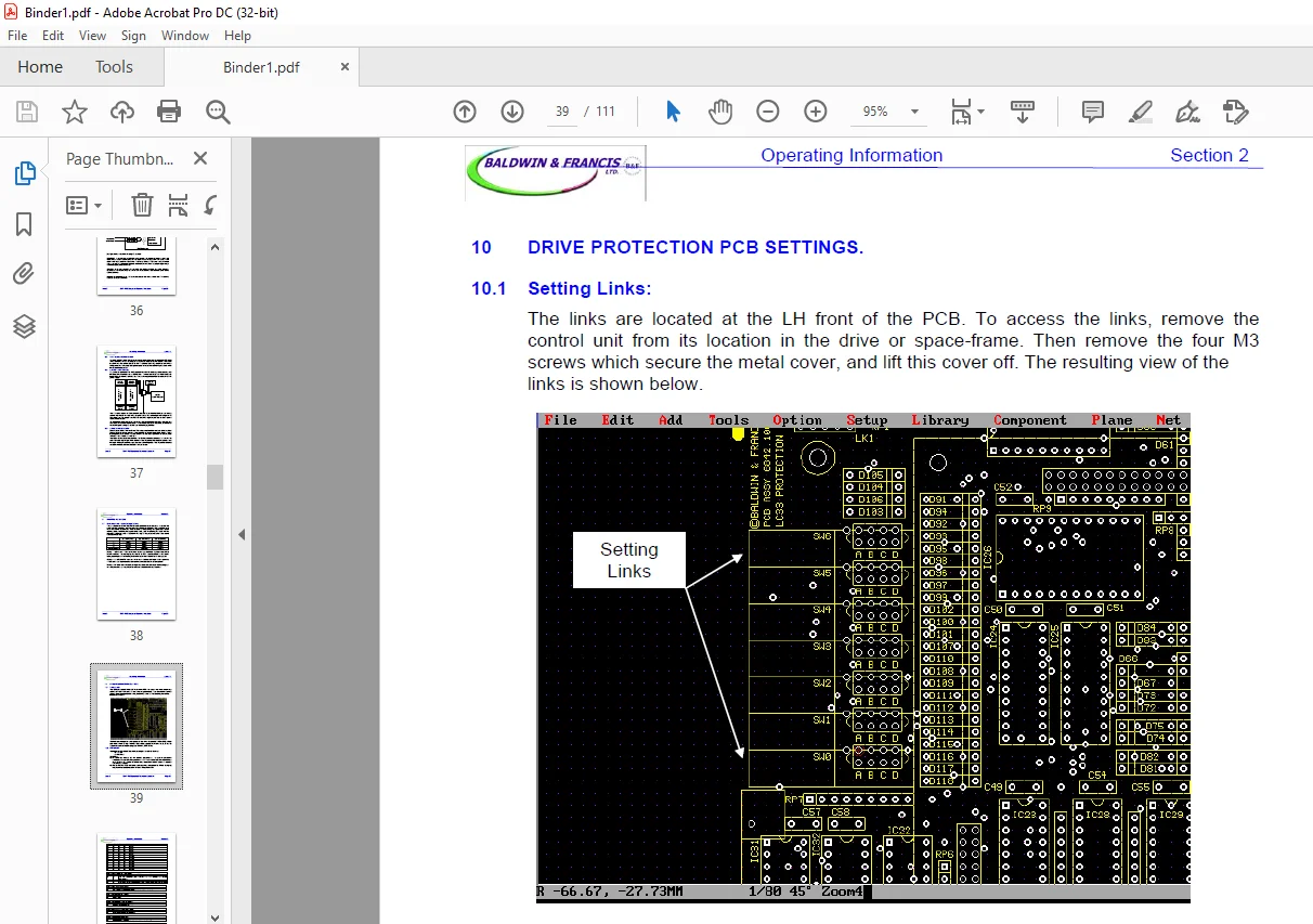
DRIVE PROTECTION PCB SETTINGS....................................... 39
	Setting Links:.................................................. 39
	FUNCTIONS....................................................... 39
HV SEARCH DIP SWITCH SETTINGS....................................... 42
INSTALLATION........................................................ 43
	Physical Installation........................................... 43
	Incoming Supply Cable and Earth Bonding......................... 43
	Outgoing cables................................................. 43
TMD POWER-UP PROCEDURE.............................................. 44
	General......................................................... 44
	Drive protection and duty settings.............................. 44
	Drive Test Procedure............................................ 45
	Checking the external control circuits and transducers.......... 45
	Auxiliary & I.S. Supplies....................................... 45
	Full Energisation............................................... 45
SECTION THREE – TECHNICAL SPECIFICATION............................. 47
PERFORMANCE DATA.................................................... 49
	General......................................................... 49
	Construction.................................................... 49
	Main Isolators Ratings.......................................... 49
	Auxiliary/ Test Isolator Rating................................. 49
	Door Interlocks................................................. 49
	Live Compartment Indication (L.C.I.)............................ 49
	Lifting Lugs.................................................... 50
	Contactor Compartment........................................... 50
	315/ 450A Drives................................................ 50
	630A Drives..................................................... 50
	Outgoing Supplies............................................... 50
	Indirect Entry.................................................. 50
	Auxiliary / Lighting Supply (Optional).......................... 50
	I.S. Supplies (Optional)........................................ 50
	RS485/232 Modbus/RTU Transmission............................... 51
	I.S. Barriered Inputs and Outputs............................... 51
	I.S. Diode Proved Digital Inputs................................ 51
	I.S. Digital (relay)/ Analogue Outputs.......................... 51
	Back Trip Circuits.............................................. 51
	Pilot Data Outputs.............................................. 51
	High Voltage Search............................................. 51
CONTACTOR PROTECTION................................................ 52
	Under / Over voltage protection :............................... 52
	Sensitive core balance earth leakage:........................... 52
	Insulated neutral earth leakage (optional):..................... 52
	Phase Sensitive Short Circuit (generally used for 3300V driv.... 52
	Current Magnitude Short Circuit (generally used for 1100V dr.... 52
	High Set Protection :........................................... 52
	Overload protection :........................................... 53
	Undercurrent Protection :....................................... 53
	Pilot Control : (positive diode- cathode to earth).............. 53
	Pilot Proving : (negative diode- anode to earth)................ 53
	I.S. Lockout :.................................................. 54
	Frozen Contactor Detection :.................................... 54
	Through Bottle Protection :..................................... 54
	Variable Anti-inch Timer :...................................... 54
SECTION FOUR – HANDLING, TRANSPORT & STORAGE........................ 55
INTRODUCTION........................................................ 57
HANDLING/ TRANSPORTATION............................................ 57
STORAGE PRECAUTIONS................................................. 57
SECTION FIVE – MAINTENANCE & FAULT FINDING.......................... 59
INTRODUCTION........................................................ 61
GENERAL............................................................. 61
	Isolator maintenance............................................ 61
	Vacuum contactor maintenance.................................... 61
	Drive chassis replacement (fixed drives)........................ 62
	Control unit replacement........................................ 62
	Changing an outgoing socket..................................... 62
	CBCT assembly replacement....................................... 63
TMD SYSTEM SOFTWARE................................................. 64
	Exec Controller Software........................................ 64
	Protection Software............................................. 64
	HVS Software.................................................... 64
SUMMARY OF DIAGNOSTIC FEATURES...................................... 65
	Live Compartment ( LCI ) and other Indications.................. 65
	Exec Controller Display......................................... 65
INTERNAL PROBLEMS................................................... 65
	Main Power Transformer Primary Fuses............................ 65
	Main Power Transformer Secondary Fuses.......................... 66
	Drive Chassis Faults / Fuses.................................... 67
	Drive Control Unit Internal Faults.............................. 67
	Contactor Auxiliary Failure..................................... 67
	Core Balance Transformer / Pilot Circuit........................ 67
SECTION SIX – PARTS LISTS........................................... 69
INTRODUCTION........................................................ 71
SECTION SEVEN – MODIFICATION INSTRUCTIONS........................... 73
INTRODUCTION........................................................ 75
AUSTDAC SIGNALS & COMMUNICATIONS.................................... 76
	Configuring the AustDAC system.................................. 77
SECTION EIGHT – APPLICATION SPECIFIC DATA........................... 79
INTRODUCTION........................................................ 81
Contents............................................................ 82
02510315............................................................ 83
03510322............................................................ 84
16510310............................................................ 85
17510302............................................................ 86
17510313............................................................ 87
19510320 Sht 1...................................................... 88
19510320 Sht 2...................................................... 89
5118.0319........................................................... 90
5118.0320........................................................... 91
5130.0505........................................................... 92
5130.0502........................................................... 93
5130.0507........................................................... 94
5439.0012........................................................... 95
Contents............................................................ 96
Sheet 1............................................................. 97
Sheet 2............................................................. 98
Sheet 3............................................................. 99
Sheet 4.............................................................100
Sheet 5.............................................................101
Sheet 6.............................................................102
Sheet 7.............................................................103
Sheet 8.............................................................104
Sheet 9.............................................................105
Sheet 10............................................................106
Questions? Email us: [email protected]
https://vimeo.com/887883136?share=copy
PLEASE NOTE:
- This is the SAME exact manual used by your dealers to fix your vehicle.
- The same can be yours in the next 2-3 mins as you will be directed to the download page immediately after paying for the manual.
- Any queries / doubts regarding your purchase, please feel free to contact [email protected]
S.V