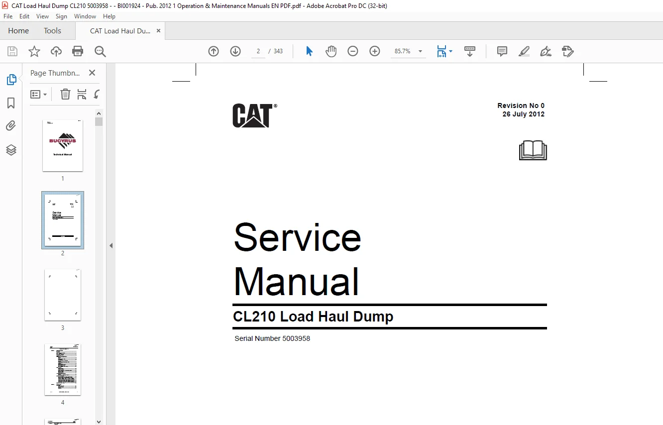
CAT CL210 Load Haul Dump Service Manual SN:5003958 – PDF DOWNLOAD
$29.95
CAT CL210 Load Haul Dump Service Manual SN:5003958 – PDF DOWNLOAD
Description
CAT CL210 Load Haul Dump Service Manual SN:5003958 – PDF DOWNLOAD
FILE DETAILS:
CAT CL210 Load Haul Dump Service Manual SN:5003958 – PDF DOWNLOAD
Language : English
Pages : 343
Downloadable : Yes
File Type : PDF
IMAGES PREVIEW OF THE MANUAL:
DESCRIPTION:
CAT CL210 Load Haul Dump Service Manual SN:5003958 – PDF DOWNLOAD
INTRODUCTION
The operation of heavy mining machinery can be hazardous. To ensure safe operation, operators and personnel must be alert, competent, correctly trained, tested and licensed in the principles, capabilities and correct operating and isolation procedures of the machinery.
This manual is designed to provide the CL210 Load Haul Dump operator and service personnel with the proper information regarding the machine’s instrumentation, operating controls and general safe working procedures. All operators and service personnel of this machine must be conversant with the information contained within this manual before operating or performing service tasks on the machine.
To ensure safe and efficient operation, the CL210 Load Haul Dump must be adequately maintained by the operators and service personnel. The operator’s pre-start inspection procedure contained in Section 6 of the Operator’s Manual must be performed before the machine is returned to active service.
DESCRIPTION
The CL210 is a 10000 kg Load Haul Dump machine. It allows it to be used for general purpose work throughout the mine, which includes carrying heavy loads, materials and supplies.
The motive force is provided by a 172 kW CAT 3126 turbocharged four-stroke inline six cylinder flameproof diesel engine package. Flameproofing of the system includes a dry exhaust conditioning system complete with exhaust and intake flame traps. The start system is pneumatic. The Diesel Control System (DCS) is an intrinsically safe electronic monitoring system. The engine power output is connected to the constant four-wheel drive system via a drive coupling through a four-speed bidirectional power shift transmission to heavy duty axles.
The CL210 utilises a dry exhaust system complete with a replaceable particulate filter, catalysed exhaust post treatment purifier and an exhaust outlet flame trap.
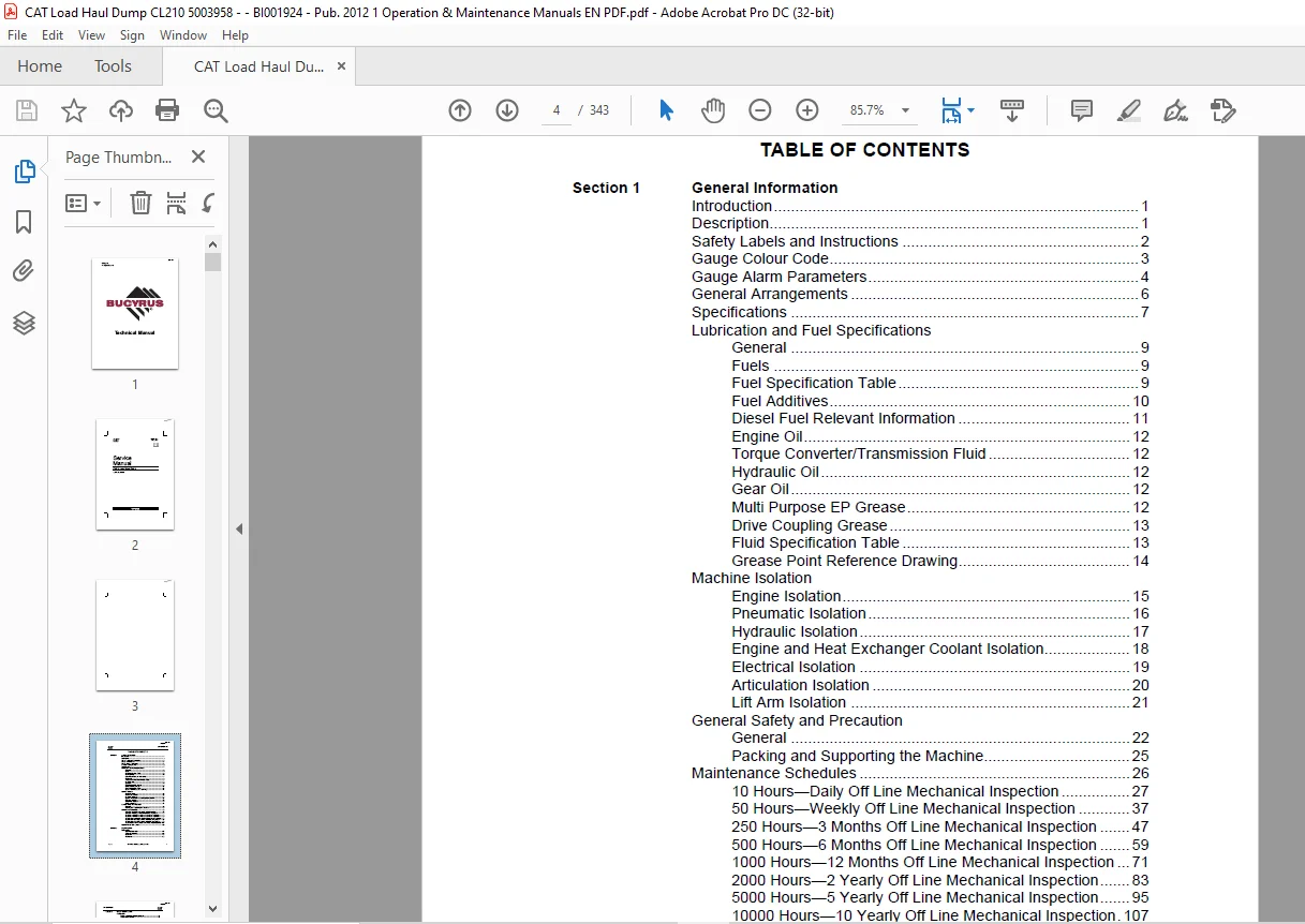
TABLE OF CONTENTS:
CAT CL210 Load Haul Dump Service Manual SN:5003958 – PDF DOWNLOAD
Section 1 General Information
Introduction 1
Description 1
Safety Labels and Instructions 2
Gauge Colour Code 3
Gauge Alarm Parameters 4
General Arrangements 6
Specifications 7
Lubrication and Fuel Specifications
General 9
Fuels 9
Fuel Specification Table 9
Fuel Additives 10
Diesel Fuel Relevant Information 11
Engine Oil 12
Torque Converter/Transmission Fluid 12
Hydraulic Oil 12
Gear Oil 12
Multi Purpose EP Grease 12
Drive Coupling Grease 13
Fluid Specification Table 13
Grease Point Reference Drawing 14
Machine Isolation
Engine Isolation 15
Pneumatic Isolation 16
Hydraulic Isolation 17
Engine and Heat Exchanger Coolant Isolation 18
Electrical Isolation 19
Articulation Isolation 20
Lift Arm Isolation 21
General Safety and Precaution
General 22
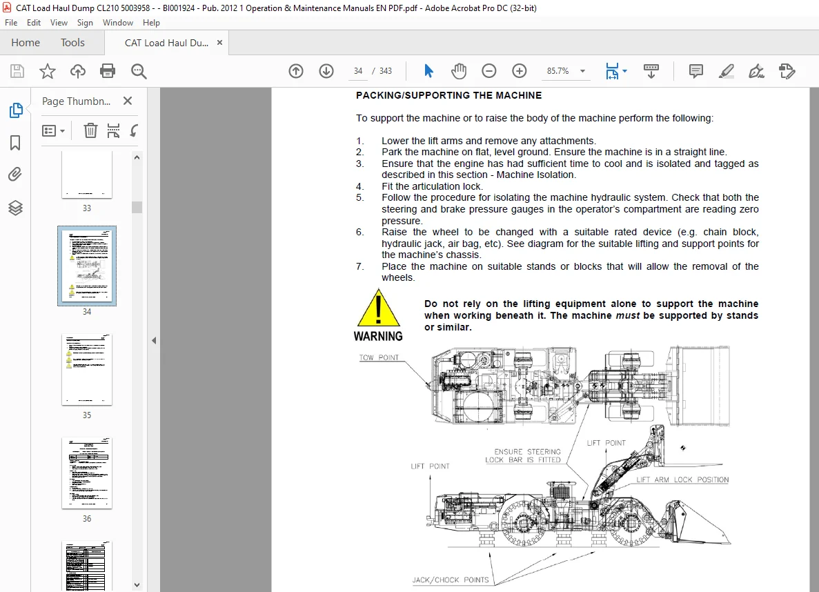
Packing and Supporting the Machine 25
Maintenance Schedules 26
10 Hours—Daily Off Line Mechanical Inspection 27
50 Hours—Weekly Off Line Mechanical Inspection 37
250 Hours—3 Months Off Line Mechanical Inspection 47
500 Hours—6 Months Off Line Mechanical Inspection 59
1000 Hours—12 Months Off Line Mechanical Inspection 71
2000 Hours—2 Yearly Off Line Mechanical Inspection 83
5000 Hours—5 Yearly Off Line Mechanical Inspection 95
10000 Hours—10 Yearly Off Line Mechanical Inspection 107
Recommended Bolt Torque 119
Section 2 Engine System
Fuel System
General Description 121
Safety Precautions 122
Fuel Tank 123
Fuel Lines 123
Section 2 Engine System (cont )
Fuel System
Primary Fuel Filter/Water Separator 124
Secondary Fuel Filter 126
Fuel System – Priming 127
Lubrication System
General Description 128
Safety Precautions 129
Oil Filter 130
Checking/Filling Engine Oil 131
Changing Engine Oil 131
Flushing the Lubrication System 132
Air Intake System
General Description 133
Safety Precautions 133
Air Cleaner/Indicator Assembly 134
Emergency Intake Shutoff Valve 135
Inlet Flame Trap/Flameproof Joints 136
Servicing Air Intake System 137
Cooling System
General Description 139
Safety Precautions 140
Engine Package 140
Expansion Tank 141
Header Tank 141
Fan Assembly 142
Water Pump Belt Tension 143
Radiator 144
Checking/Filling and Flushing Coolant System 146
Flushing a Contaminated Cooling System 147
Exhaust System
General Description 148
Safety Precautions 149
Exhaust Downpipe 149
Exhaust Purifier 151
Exhaust Heat Exchanger 153
Exhaust Particulate Filter 166
Exhaust Outlet Flame Trap 168
Flame Path Joints or Fixed Connections 172
Exhaust Emission Testing Procedure 172
Engine Exhaust Cooling System 173
Throttle Control
General Description 176
Safety Precautions 176
Cable Adjustment 177
Engine System Trouble Shooting 178
Section 3 Transmission and Drive Train
Engine Drive Coupling
General Description 183
Safety Precautions 183
Checking and Greasing Drive Coupling 184
Removal and Installation of Drive Coupling 185
Section 3 Transmission and Drive Train (cont )
Transmission/Torque Converter
General Description 186
Safety Precautions 188
Checking/Filling the Transmission Oil 189
Changing the Transmission Oil Filter Element 190
Changing the Transmission Oil 191
Troubleshooting Guide 192
Service Data 194
Front and Rear Axle
General Description 196
Safety Precautions 196
Checking/Filling the Planetary Wheel End Oil Level 197
Checking/Filling the Axle Centre Oil Level 198
Changing Oil In Axle Centres, Wheel Ends and Liquid Cooled
Brakes 200
Checking Wear of the Posi-Stop Brake Assemblies 201
Drive Lines
General Description 202
Safety Precautions 203
Greasing and Inspecting Drive Lines 204
Removing and Installing the Rear Drive Lines 204
Removing and Installing the Front Drive Lines 205
Removing and Installing the Upper Drive Lines 206
Wheel and Tyre Assemblies
General Description 207
Safety Precautions 207
Removal 207
Installation 209
Section 4 Hydraulic System
General Description 211
Safety Precautions 212
Hydraulic Isolation 213
Pumps and Mountings
Steering/Brake Pump 214
Main Hydraulic Pump 217
Auxiliary Hydraulic Pumps 218
Hydraulic Tank
Checking and Filling Hydraulic Oil 219
Changing Hydraulic Oil 220
Checking and Replacing Return Filter 221
Steering and Brake Hydraulic Manifold 222
Steering/Brake Pump Pressure Filter 226
Steering Circuit
Steering Accumulator 228
Steering Control Valve 229
Brake Circuit
Brake Accumulator 230
Brake Valve 231
Brake Heads 235
Section 4 Hydraulic System (cont )
Attachment Controls
Control Levers 236
Main Control Valve Bank 238
Tilt and Lift Circuits 240
RAS Attach and PTO Circuits 241
Alternator/Heat Exchanger Circuit 242
Cooling Fan Circuit 244
Hydraulic Schematic 245
Section 5 Electrics and Instruments
Electrical System
General Description 247
Safety Precautions 247
Alternator, Lights and Hour Meter General Arrangement 248
Electric Lighting Components 249
Engine Service Hour Meter 252
Electrical System Troubleshooting 253
Alternator and Drive Assembly
General Description 254
Safety Precautions 254
Alternator Assembly 254
Alternator Drive Assembly 256
Diesel Control System (DCS)
General Description 257
Power Supply 257
Display Illustrations 258
Display Assemblies 268
General Arrangement 269
Switches 270
Sensors 270
Sensor Locations 271
Instructions for Diesel Control System Head 274
System Operation 280
Fault Diagnosis Guide 281
Section 6 Frame Components
General Description 285
Safety Precautions 285
Front Frame
Chassis 286
Lift Arm
General 288
Fitting and Removal of Lift Arm Lock 289
Rapid Attach Back Plate (RAS) Assembly 290
Rear Frame
Chassis 292
Operator’s Compartment 293
Compartment Door Assembly 294
Canopy Assembly 295
Operator’s Seating 297
Articulation Joint 298
Covers 300
Section 7 Pneumatic System
General Description 301
Pneumatic Schematic 302
Safety Precautions 303
Air Compressor
Compressor Mounting 304
Compressor 304
Air Receiver 305
Starter Motor 308
Safety Circuit
Diesel Control System 309
Safe Start System 309
Brake and Transmission Interlock System 310
Operator’s Horn 311
Pneumatic System Troubleshooting 312
Section 8 Attachments and Accessories
General Description 313
Safety Precautions 315
Spade Lip Ejector Bucket 316
10000 kg Side Shift Forks 318
Hydraulic Reeler 320
Elevated Work Platform 324
7000 kg Slew Jib Crane 327
Fuel Pod 328
Contact us: [email protected]
https://vimeo.com/889076766?share=copy
S.S