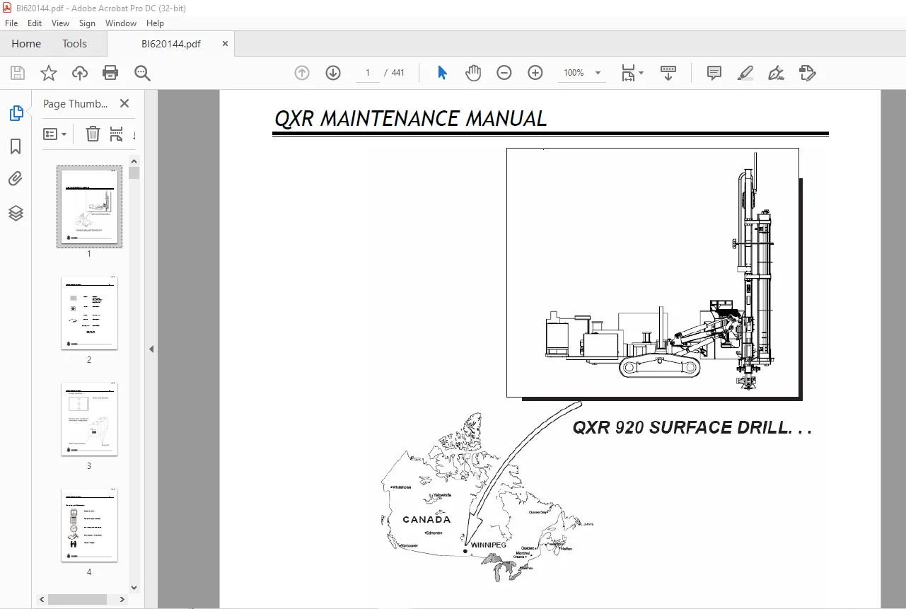
CAT CUBEX QXR 920 Surface Drill Maintenance Manual BI620144 – PDF DOWNLOAD
$29.95
CAT CUBEX QXR 920 Surface Drill Maintenance Manual BI620144 – PDF DOWNLOAD
Description
CAT CUBEX QXR 920 Surface Drill Maintenance Manual BI620144 – PDF DOWNLOAD
FILE DETAILS:
CAT CUBEX QXR 920 Surface Drill Maintenance Manual BI620144 – PDF DOWNLOAD
Language : English
Pages : 441
Downloadable : Yes
File Type : PDF
IMAGES PREVIEW OF THE MANUAL:
DESCRIPTION:
CAT CUBEX QXR 920 Surface Drill Maintenance Manual BI620144 – PDF DOWNLOAD
Operating/Maintenance Safety:
When operating this machine, the safety of the operating crew and other workers in the vicinity
must be the principal concern. All persons operating this machine must understand the necessary
safety precautions to help minimize the risk of accidents and injury. The operator must ensure that
all fire fighting equipment is in working order, inspect the condition of all walkways, handrails,
ladders, and guards.
All safety equipment such as hardhat, steel cap boots, safety goggles, hearing protection, gloves,
etc., should be worn while operating this Machine.
Snug fitting clothing should be worn by the operator in or around the drill so as not to be caught
up in any moving machinery.
Special precautions must be taken by everyone when using a drill rig in the vicinity of electrical
power lines and other utilities. Underground electricity is as dangerous as overhead electricity.
Be aware and always suspect the existence of underground utilities such as electrical power, gas,
petroleum, telephone, sewer, and water.
Electricity can shock, burn and cause death.
• Overhead and buried utilities should be located, noted and emphasized on all boring
location plans and boring assignment sheets.
• When overhead electrical power lines exist at or near a drilling site or project,
consider all wires to be live and dangerous.
• Watch for sagging power lines before entering a site. Do not lift power lines to
gain entrance.
• Before raising the drill rig mast on a site in the vicinity of power lines, walk
completely around the drill rig. Determine what the minimum distance from any point on the drill
rig to the nearest power line will be when the mast is raised and/or being raised. Do not raise the
mast or operate the drill rig within a minimum of three (3) meters of any electrical power line or
other obstruction.
• Only move the drill rig with the mast down.
If there are any questions concerning the safety of drilling on sites in the vicinity of overhead
power ll your supervisor.
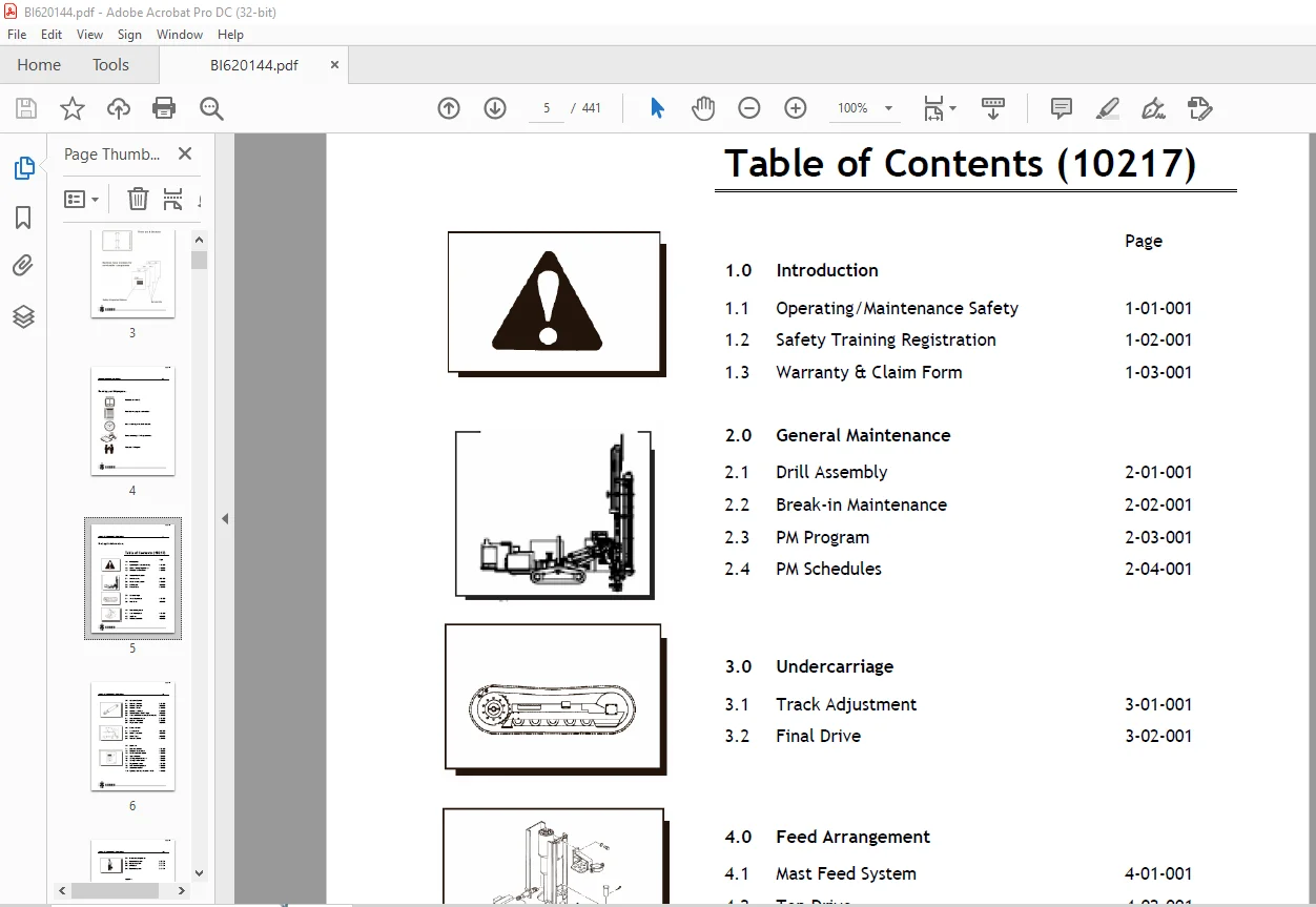
TABLE OF CONTENTS:
CAT CUBEX QXR 920 Surface Drill Maintenance Manual BI620144 – PDF DOWNLOAD
Planning your PM program…..................................................... 4
Finding the Information…...................................................... 5
1.1 Operating/Maintenance Safety...................................... 9
Drill Operation and Maintenance Safety................................ 11
General Safety Instructions............................................. 11
Safety Instructions for Driving and Operating........................... 12
Safety Instructions for Servicing....................................... 12
Extinguishing Fires....................................................... 18
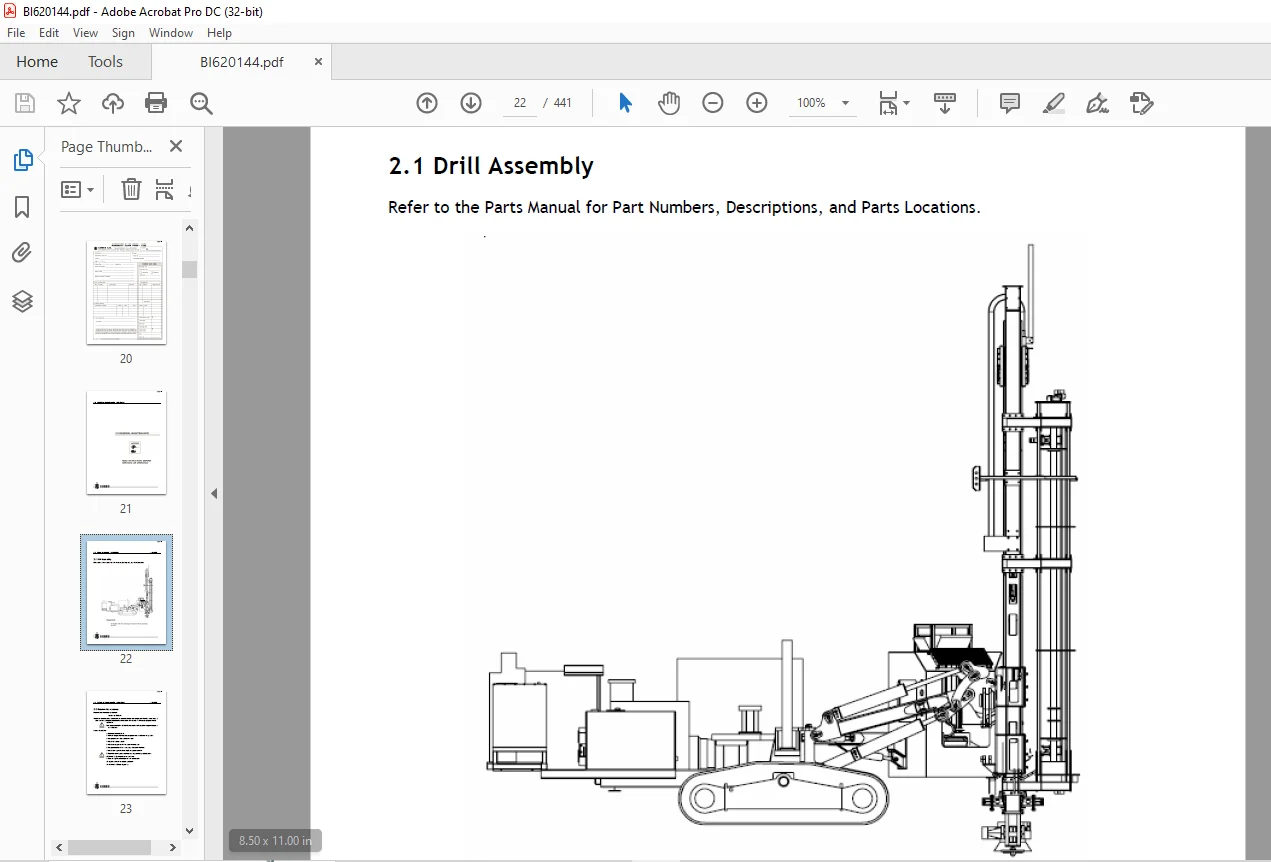
2.1 Drill Assembly............................................................ 22
2.2 Break-in Maintenance...................................................... 23
2.3 Preventative Maintenance Program.......................................... 24
2.3.1 Lubrication......................................................... 26
2.3.2 Lubrication Cross-over.............................................. 27
2.3.3 Rock Drill Grease................................................... 28
2.3.4 Lubrication Points and Intervals.................................... 28
2.3.5 Centralized Machine Lubrication..................................... 29
Greaser Assembly...................................................... 31
2.3.6 Drill Filtration Points and Intervals............................... 33
2.3.7 Bolt Torque......................................................... 34
2.3.8 Pipe Thread Grease Pump............................................. 35
2.3.8.1 Preventative Maintenance Tasks................................ 35
2.3.8.2 Safety........................................................ 36
2.3.8.3 Maintenance................................................... 37
2.3.9 Annual Maintenance of the Coolant Heater............................ 38
2.4 Recommended Tools:........................................................ 43
3.1 Track Adjustment.......................................................... 49
3.2 Final Drive............................................................... 50
4.1 Mast Feed System..........................................................264
4.1.1 QXR Feed Chain Adjustment...........................................266
4.1.2 Slider Adjustment...................................................269
4.1.3 Carrier Block.......................................................270
4.1.4 Feed Chain Block....................................................271
4.1.5 Jib Boom............................................................272
4.1.6 Lower Mast..........................................................273
4.1.6.1 Overhaul procedure............................................274
4.2 Top Drive.................................................................275
4.2.1 Checking Bearing Pre-load...........................................276
4.2.2 Adjusting Bearing Pre-load..........................................277
4.2.3 Removing Top Drive..................................................277
4.2.3.1 Using the Right Equipment.....................................278
4.2.4 Disassembly Procedure...............................................279
4.2.5 Installation of Pinion Gears and Bearings...........................280
4.2.6 Driveshaft Assembly and Installation................................281
4.2.7 Setting Bearing Preload.............................................287
4.2.8 Installing Upper Seal and Housing...................................289
4.2.9 Installing Air Swivel and Hydraulic Motors..........................291
4.2.10 Saver Sub..........................................................293
4.2.10.1 Removal......................................................293
4.2.10.2 Installation.................................................295
4.2.11 Air Swivel.........................................................296
4.2.11.1 Removing Air Swivel..........................................296
4.2.11.2 Installation of Air Swivel...................................297
4.2.11.3 Dismantling Air Swivel.......................................299
4.2.11.4 Inspection of Parts..........................................301
4.2.11.5 Assembly Procedure...........................................302
4.3 Carousel Assembly.........................................................310
4.3.1 Carousel Adjustment.................................................313
4.3.1.1 Pipe Clamp Adjustment.........................................313
4.3.1.2 Clamp Arm Adjustment..........................................314
5.1 Hydraulic Symbols.........................................................317
5.2 Hydraulic Circuits........................................................318
5.3 Hydraulic Pump............................................................321
5.3.1 Installation........................................................322
5.3.1.1 Pre Start-up..................................................322
5.3.1.2 Start-up......................................................322
5.3.2 Adjustments.........................................................324
5.3.2.1 System (Operating) Pressure Adjustment........................324
5.3.2.2 Stand-by Pressure Adjustment..................................324
5.3.3 Testing the Pump....................................................325
5.3.4 Troubleshooting the Pump............................................327
5.3.5 Factors Affecting the Pump’s Life...................................328
5.3.5.1 Contaminated Fluid............................................328
5.3.5.2 Poor Suction Conditions.......................................329
5.3.5.3 Excessive Case Pressure.......................................330
5.3.5.4 Too Low an Operating Pressure.................................330
5.3.5.5 Cavitation/Aeration...........................................331
5.4 Hydraulic Cylinders.......................................................332
5.4.1 Double Acting Cylinders.............................................333
5.4.2 Cylinder Inspection.................................................333
5.4.3 Cylinder Overhaul...................................................333
5.5 Control Valves – On/Off Types.............................................334
5.5.1 Control Valves......................................................336
5.5.2 Relief Valve Adjustment.............................................337
5.5.3 Valve Pressure Adjustment...........................................338
5.5.4 Valve Flow Adjustment...............................................338
5.5.5 Valve Overhaul......................................................338
5.5.6 Valve Sections......................................................340
5.5.7 Solenoid............................................................340
5.5.8 Lever Section.......................................................340
5.5.9 Valve Assembly......................................................342
5.5.10 Inlet Section......................................................342
5.6 Motorized Pulldown and Holdback Control Adjustment........................344
5.6.1 Adjusting Pulldown – Maximum Pressure...............................344
5.6.2 Adjusting Holdback – Maximum Pressure...............................344
5.7 Counterbalance Valves.....................................................345
5.7.1 Making Adjustments..................................................346
5.7.2 Troubleshooting.....................................................347
5.8 Hydraulic Filtration......................................................348
5.8.1 Change Hydraulic Fluid Every 2000 Hours.............................349
5.8.2 Return Filters......................................................349
5.8.3 Pressure Filter Element.............................................350
5.9 Proportional Valves.......................................................351
5.9.1 Proportional Valve Settings.........................................351
5.9.2 Flow Settings.......................................................352
5.9.3 Pressure Setting....................................................353
6.1 Air Schematic.............................................................356
6.2 Sullair Compressor........................................................358
6.2.1 Compressor Unit Functional Description .............................359
6.2.2 Compressor Discharge System Functional Description..................361
6.2.3 Compressor Cooling and Lubrication System Functional Description....363
6.2.4 Air Inlet System Functional Description.............................365
6.2.5 Lubrication Guide...................................................366
6.2.6 Application Guide...................................................366
6.2.7 Control System......................................................367
6.2.7.1 Purpose of Controls...........................................367
6.2.7.2 Butterfly Inlet Valve Functional Description..................371
6.2.7.3 Closed Inlet Start Program....................................372
6.2.7.4 Normal Operation..............................................373
6.2.7.5 Modulation....................................................373
6.2.7.6 Unload........................................................373
6.2.7.7 Compressor Start Up Mode and Running Mode Low Air Pressure....374
6.2.7.8 Manual Unload Mode............................................375
6.2.7.9 Running Mode 350 psi Air Pressure.............................376
6.2.7.10 Running Mode 500 psi Air Pressure............................377
6.2.7.11 Instrumentation and Protection...............................378
6.2.7.12 Start Up and Shutdown Procedures.............................380
6.2.7.13 Adjustment Procedures........................................382
6.2.8 Compressor Maintenance..............................................383
6.2.8.1 Main Fluid Filter Service.....................................383
6.2.8.2 Thermal/Bypass Valve..........................................384
6.2.8.3 Separator Element Replacement.................................385
6.2.8.4 Running Blowdown Valve Maintenance............................387
6.2.8.5 Shutdown Blowdown Valve Maintenance...........................388
6.2.8.6 Minimum Pressure/Check Valve Maintenance......................389
6.2.8.7 Discharge Check Valve Maintenance.............................390
6.2.8.8 Safety Valve..................................................391
6.2.8.9 Pressure Regulator (Low / High Air Pressure Regulator)........392
6.2.8.10 Fluid Stop Valve.............................................394
6.2.9 Screw Compressor....................................................395
6.2.9.1 Screw Compressor Arrangement..................................395
Compressor Operator Daily Checklist.......................................396
6.2.9.3 Maintenance Schedules.........................................397
6.2.9.4 Compressor Lubrication Crossover..............................398
6.2.9.5 Compressor Troubleshooting....................................399
6.3 Water Pump................................................................401
6.3.1 Pump Speed Adjustment...............................................402
6.3.2 Dismantling of Valves...............................................403
6.3.3 Assembling of Valves................................................403
6.3.4 Dismantling the Pumping Section.....................................404
6.3.5 Pump Assembly.......................................................404
6.3.6 Removing Sleeves and Seals..........................................405
6.3.7 Installing Sleeves and Seals........................................405
6.3.8 Servicing the Crankcase.............................................406
6.3.9 Pump Installation...................................................406
6.4 Grease Injection..........................................................407
6.4.1 To Fill Reservoir...................................................409
6.4.2 To Prime System.....................................................409
6.4.3 Operation...........................................................409
6.4.4 Adjusting Flow Rate.................................................410
6.4.4.1 Setting for a 4” Hammer.......................................410
6.4.4.2 Setting for a 6” Hammer.......................................410
6.4.5 PanelView Settings for QXR..........................................412
7.1 Electrical Circuits.......................................................414
7.2 Electrical Components.....................................................415
7.3 On/Off Valve Activation...................................................416
7.4 Types of Valves...........................................................417
7.5 Testing of Valve Solenoids................................................417
7.6 Testing On/Off Valves.....................................................418
7.7 Proportional Valves.......................................................419
7.8 Fault Monitoring System...................................................420
7.8.1 Testing Proportional Valves.........................................420
7.9 Accra-Feed PLC System.....................................................422
7.9.1 Accra-Feed Operation................................................422
7.9.2 Accra-Feed Components...............................................422
7.9.3 PLC Operation.......................................................423
7.9.4 Maintenance of PLC in Accra-Feed System.............................423
7.9.5 Troubleshooting Guide...............................................424
7.10 Operator Interface PanelView 1000........................................427
7.10.1 Maintenance of PanelView Terminal..................................427
7.10.2 Troubleshooting PanelView Terminal.................................428
7.10.3 Alarm Messages on the Terminal.....................................430
8.0 Troubleshooting...........................................................432
8.1 Troubleshooting Mechanical Systems........................................433
Tramming does not move or move straight...................................433
Tramming is too slow or lacks power.......................................433
Brakes are slipping.......................................................433
Excessive noise or vibration when tramming................................434
Mast swing does not rotate................................................434
Mast rotates erratically or rotates after setting.........................434
Mast rocks back and forth.................................................434
Hydraulic cylinders not operating.........................................434
Cylinder creep............................................................435
Centralizer does not retract..............................................435
Oil leakage at stinger cylinder...........................................435
Pulldown control does not function correctly..............................435
Holdback control does not function correctly..............................435
Top drive does not rotate, or rotation is slow or rough...................435
Splined piston in top drive does not retract..............................436
Rotation and Feed joysticks produce uneven speeds in both directions......436
8.2 Troubleshooting Hydraulic Systems.........................................437
Fluid is hot..............................................................437
System is noisy...........................................................437
Fluid quickly contaminates................................................437
Fluid is foaming..........................................................437
Valve Solenoid Malfunction................................................437
Insufficient pressure or flow.............................................438
Pump is noisy or vibrates.................................................438
Pump does not run.........................................................438
Hydraulic motors or cylinders do not respond..............................438
Rotation and Feed joysticks produce uneven speeds in both directions......438
8.3 Troubleshooting Air Systems...............................................439
Air pressure is zero or low...............................................439
Water pump pressure is zero...............................................439
Water pump pressure is low................................................439
Water pump runs extremely rough...........................................439
Water pump leaking........................................................439
Grease delivery is incorrect..............................................440
8.4 Troubleshooting Electrical Systems........................................441
Engine does not start.....................................................441
Tram controls (joysticks only) are insensitive............................441
Hydraulic motors or cylinders not operating...............................441
Rotation and Feed joysticks produce uneven speeds in both directions......441
Valve Solenoid Malfunction................................................441
Customer Support: [email protected]
PLEASE NOTE:
- This is the SAME manual used by the dealers to troubleshoot any faults in your vehicle. This can be yours in 2 minutes after the payment is made.
- Contact us at [email protected] should you have any queries before your purchase or that you need any other service / repair / parts operators manual.
S.V