Trusted Business
Verified & Licensed
Virus Free Files
100% Safe Downloads
Secure Payment
SSL Protected
Instant Delivery
Available Immediately
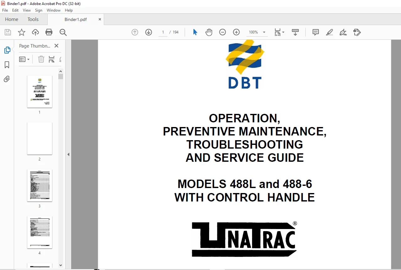
CAT DBT 488L & 488-6 OPERATION PREVENTIVE MAINTENANCE TROUBLESHOOTING & SERVICE GUIDE (A6474X235) – PDF DOWNLOAD
$24.95
- CAT DBT 488L & 488-6 OPERATION PREVENTIVE MAINTENANCE TROUBLESHOOTING & SERVICE GUIDE (A6474X235) – PDF DOWNLOAD
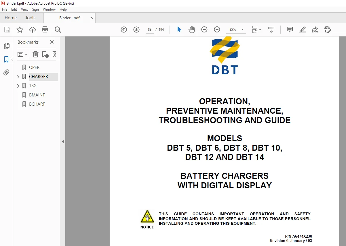
- CAT DBT 5 DBT 6 DBT 8 DBT 10 DBT 12 & DBT 14 OPERATION PREVENTIVE MAINTENANCE TROUBLESHOOTING & GUIDE
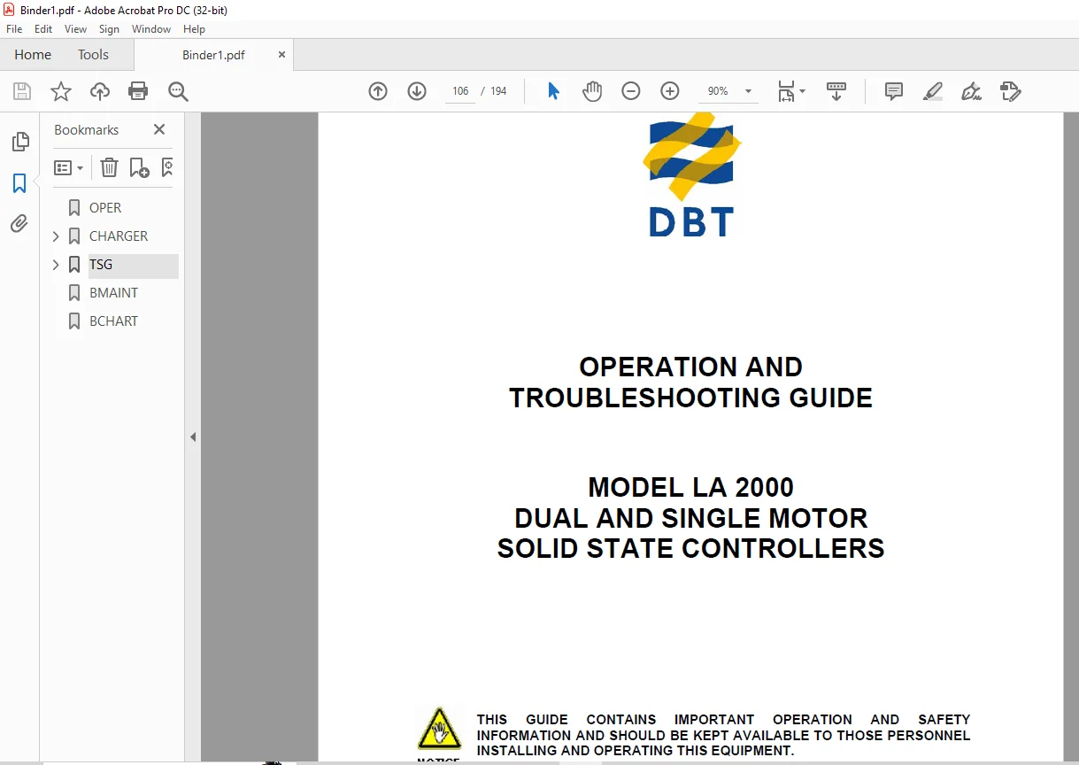
- CAT LA 2000 DUAL & SINGLE MOTOR SOLID STATE CONTROLLERS OPERATION & TROUBLESHOOTING GUIDE
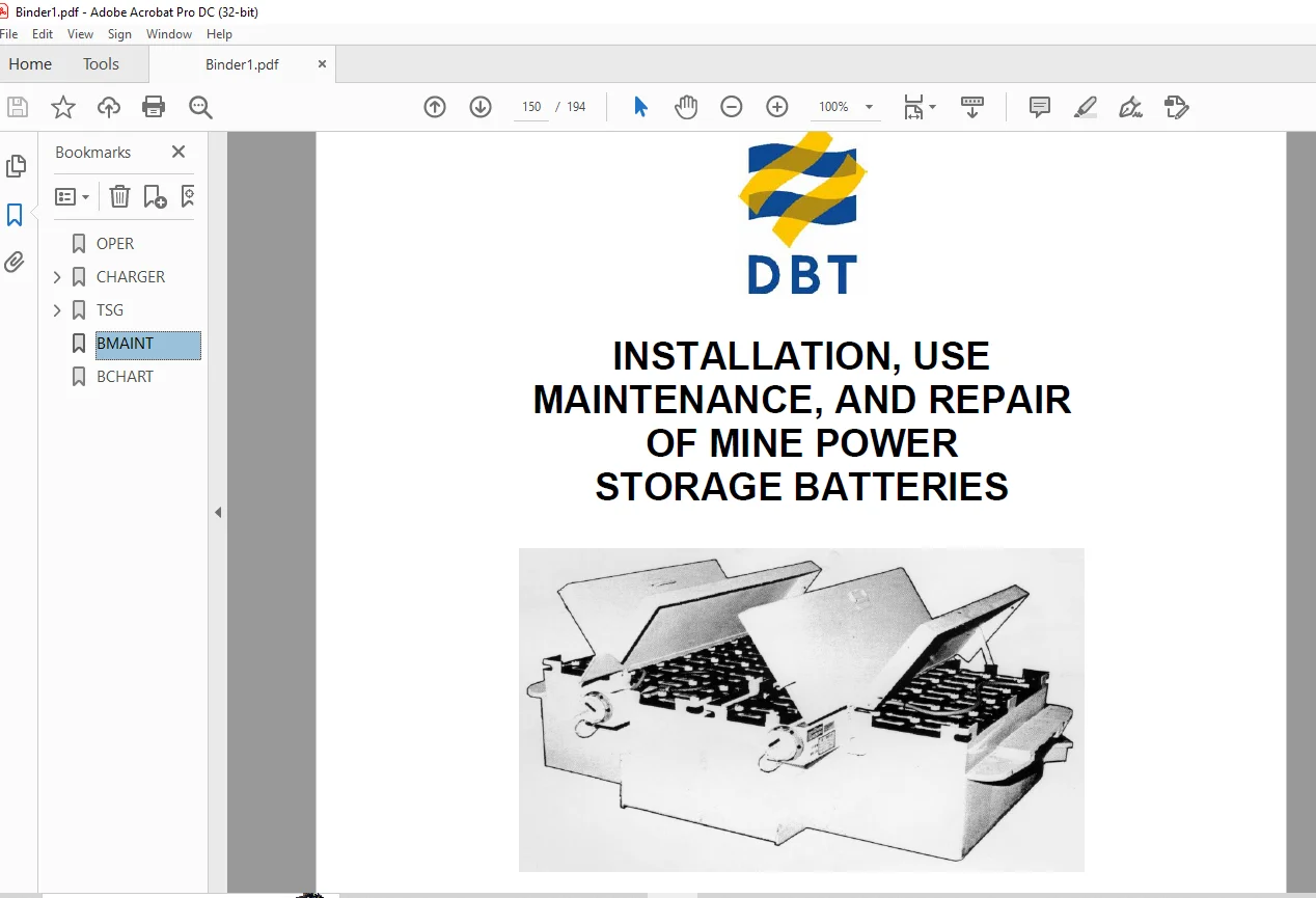
- CAT DBT INSTALLATION USE MAINTENANCE & REPAIR OF MINE POWER STORAGE BATTERIES
Instant PDF Download
Available immediately
Save to Your Device
Download & keep forever
Antivirus Scanned
100% virus-free
Trusted Worldwide
175,000+ customers
Description
CAT DBT 488L & 488-6 OPERATION PREVENTIVE MAINTENANCE TROUBLESHOOTING & SERVICE GUIDE (A6474X235) – PDF DOWNLOAD
FILE DETAILS:
CAT DBT 488L & 488-6 OPERATION PREVENTIVE MAINTENANCE TROUBLESHOOTING & SERVICE GUIDE (A6474X235) – PDF DOWNLOAD
Language : English
Pages :194
Downloadable : Yes
File Type : PDF
DESCRIPTION:
- CAT DBT 488L & 488-6 OPERATION PREVENTIVE MAINTENANCE TROUBLESHOOTING & SERVICE GUIDE (A6474X235) – PDF DOWNLOAD
- CAT DBT 5 DBT 6 DBT 8 DBT 10 DBT 12 & DBT 14 OPERATION PREVENTIVE MAINTENANCE TROUBLESHOOTING & GUIDE
- CAT LA 2000 DUAL & SINGLE MOTOR SOLID STATE CONTROLLERS OPERATION & TROUBLESHOOTING GUIDE
- CAT DBT INSTALLATION USE MAINTENANCE & REPAIR OF MINE POWER STORAGE BATTERIES
- This manual is intended to provide GENERAL product information for the Model 488 Series UN-A-TRAC®. The illustrations, descriptions and procedures contained in this publication apply only to this Model 488 UN-A-TRAC®. DBT America Inc. reserves the right to revise models and designs without prior notice.
- This Model 488 UN-A-TRAC® was manufactured under the guidelines, procedures and requirements of the U. S. Federal Coal Mine Health and Safety Act, Code of Federal Regulations, Title 30, Chapter 1, Subpart 0, Part 75 for underground coal mines, and other applicable non-U. S. regulatory agency standards.
- At the completion of the manufacturing process, this Model 488 UN-A-TRAC® was issued the appropriate approval numbers and nameplates indicating it met the technical requirements of these regulatory agencies. Any change to the design or structure of this Model 488 UN-A-TRAC®, without the consent of DBT America Inc., and these regulatory agencies, or any repair or replacement of parts contrary to DBT America’s instructions, may invalidate these approvals and render this Model 488 UN-A-TRAC® unsafe to operate.
- Strict compliance with all Federal and State Mining laws, regulations and practices regarding the safe operation and maintenance of underground mining equipment and strict adherence to the instructions in this manual is necessary for the personal safety of those working on or around this Model 488 UN-A-TRAC®.
- While this manual attempts to anticipate the most important operations and maintenance needs for this Model 488 UN-A-TRAC®, unforeseen circumstances may arise that have not been addressed in this manual. If any concerns or questions arise, please contact your DBT America Service Representative immediately.
- This work contains information protected under trade secret and other intellectual property laws, and is protected under the U. S. Copyright Act of 1976, as amended. This work is provided under license and the license is nontransferable. Distribution and access is limited only to authorized personnel. Disclosure, reproduction, distribution or unauthorized use may be a violation of federal and state laws and may subject the unauthorized user to criminal liability.
IMAGES PREVIEW OF THE MANUAL:
TABLE OF CONTENTS:
CAT DBT 488L & 488-6 OPERATION PREVENTIVE MAINTENANCE TROUBLESHOOTING & SERVICE GUIDE (A6474X235) – PDF DOWNLOAD
OPER......................................................  1
CHARGER................................................... 83
	PREFACE............................................... 86
	SYMBOLS AND SPECIAL NOTATIONS......................... 87
	MAJOR HAZARDS......................................... 89
	SAFETY PRECAUTIONS AND GUIDELINES..................... 90
	OVERVIEW.............................................. 90
	LOCATION.............................................. 90
	PRE-START............................................. 90
	MAINTENANCE........................................... 91
	THEORY OF OPERATION FERRORESONANT DESIGN.............. 93
	INTRODUCTION.......................................... 94
	GENERAL............................................... 94
	GENERAL INFORMATION................................... 95
	RECEIVING INSTRUCTIONS................................ 95
	HANDLING.............................................. 95
	NOMENCLATURE PLATES................................... 95
	ADJUSTMENTS........................................... 95
	SPARE PARTS........................................... 95
	RATINGS AND SPECIFICATIONS............................ 96
	OUTPUT RATINGS........................................ 96
	INPUT RATINGS......................................... 96
	TYPICAL ELECTRICAL SPECIFICATIONS..................... 96
	STANDARD FEATURES..................................... 97
	OPTIONAL GROUND INTEGRITY............................. 97
	ENVIRONMENTAL RATINGS................................. 98
	INSTALLATION INFORMATION.............................. 99
	MINIMUM WIRE SIZES.................................... 99
	ELECTRICAL CONNECTIONS AND FIELD WIRING............... 99
	OPERATION.............................................101
	START UP (ELECTRONIC TIMER)...........................101
	ADJUSTMENTS...........................................102
	CIRCUIT OPERATION.....................................102
	TROUBLESHOOTING.......................................103
	GENERAL INSPECTION....................................103
	SERVICE INFORMATION...................................103
	SYMPTOMS AND CAUSES...................................104
	GROUND AND SHORT CIRCUIT TEST.........................104
	TROUBLESHOOTING AND REPLACING POWER SILICON DIODES....105
	CHECKING CAPACITORS...................................105
TSG.......................................................106
	TABLE OF CONTENTS.....................................107
	PREFACE...............................................108
	SYMBOLS AND SPECIAL NOTATIONS.........................109
	MAJOR HAZARDS.........................................111
	SAFETY PRECAUTIONS AND GUIDELINES.....................112
	OVERVIEW..............................................112
	MAINTENANCE...........................................112
	INTRODUCTION..........................................113
	LA 2000: INNOVATIVE SPEED CONTROL BY DBT AMERICA......113
	GENERAL SPECIFICATIONS................................118
	FAIL-SAFE OPERATION WILL INCLUDE THE FOLLOWING........118
	DESCRIPTION OF FEATURES...............................119
	LA 2000 MOTOR CONTROLLER CONSIST OF...................119
	LA 2000 MOTOR IGBT PANEL (POWER CONNECTIONS)..........119
	MICROPROCESSOR BASED LOGIC CARD (CONTROL INPUTS)......119
	CONFIGURATION JUMPER TABLE............................121
	OPTIONAL DASHBOARD DISPLAY FEATURES (SEE FIGURE 9)....121
	FAULT MESSAGE CHART...................................122
	OPTIONAL HAND HELD DIAGNOSTICS/CALIBRATOR UNIT........124
	PERSONALITY ADJUSTMENT PROCEDURE......................125
	TRACTION PERSONALITIES (CONTROLLER ADJUSTMENTS).......125
	TRACTION STATUS DISPLAY...............................127
	TRACTION TEST DISPLAY.................................129
	TRACTION BDI DISPLAY..................................130
	ERROR CODE LEGEND (STATUS DISPLAY)....................131
	TROUBLESHOOTING.......................................132
	IGBT MEASUREMENTS.....................................133
	INDIVIDUAL IGBT MEASUREMENTS..........................134
	DIODE MEASUREMENTS....................................135
	DIODE MEASUREMENTS....................................136
	PANEL MEASUREMENTS....................................137
	DRIVER MEASUREMENTS...................................138
	IGBT DUAL MOTOR PANEL, FIGURE 16......................140
	IGBT SINGLE MOTOR PANEL,FIGURE 17.....................141
	IGBT HEAT SINK ASSEMBLY, FIGURE 18....................142
	SINGLE MOTOR PANEL HARNESS ASSEMBLY, FIGURE 19........143
	DUAL MOTOR PANEL HARNESS ASSEMBLY, FIGURE 20..........144
	DASHBOARD DISPLAY, FIGURE 21..........................145
	DUAL "Y" HARNESS, FIGURE 22...........................146
	HARNESS FOR DASHBOARD DISPLAY, FIGURE 23..............147
	CALIBRATOR UNIT, FIGURE 24............................148
	LA 2000 PUMP MOTOR SHUNT, FIGURE 25...................148
	LA 2000 PANEL WIRING HARNESS, FIGURE 26...............149
BMAINT....................................................150
BCHART....................................................194
Questions? Email us: [email protected]
https://vimeo.com/890718406?share=copy
S.S