Cat EL2000 Shearer Operating Manual – PDF DOWNLOAD
$27.95
Cat EL2000 Shearer Operating Manual – PDF DOWNLOAD
Description
Cat EL2000 Shearer Operating Manual – PDF DOWNLOAD
FILE DETAILS:
Cat EL2000 Shearer Operating Manual – PDF DOWNLOAD
Language :English
Pages :339
Downloadable : Yes
File Type : PDF
IMAGES PREVIEW OF THE MANUAL:

DESCRIPTION:
Cat EL2000 Shearer Operating Manual – PDF DOWNLOAD
About this manual
This chapter contains important information which will simplify the use of this manual for you. In addition it includes information about the structure of the manual and on the characters and symbols used.
machine type, you will endanger yourself and others.
Ensure that the serial number on you machine corresponds with the
following :
Ident. no.: EL2000-028 & 029
The operating manual must be accessible at all times to all persons
working on, or with, this shearer.
This operating manual is intended for all persons working with or on
the shearer.
All persons working with the shearer must have read this manual.
This includes persons:
responsible for transport
carrying out the drivage
carrying out erection / dismantling
operating the shearer
eliminating faults
carrying out routine work on the face
carrying out maintenance operations
carrying out repairs
TABLE OF CONTENTS:
Cat EL2000 Shearer Operating Manual – PDF DOWNLOAD
Table of content
1. About this manual
Before starting work 1.3
Who is this operating manual intended for? 1.3
2. Your safety
Personnel 2.4
Operation 2.4
Installation and repair 2.4
Operating conditions 2.4
Unauthorised use 2.4
Safety instructions 2.5
General rules 2.5
Electrical isolation of the shearer 2.11
To electrically isolate the shearer: 2.11
3. Storage and transport
Storage 3.3
Storage of the equipment 3.3
Transport 3.4
Load Units, Dimensions and Weights 3.4
Before Transport 3.4
Transport of the Components 3.4
Transporting The Machine Underground 3.5
Cutting Drum Removal 3.8
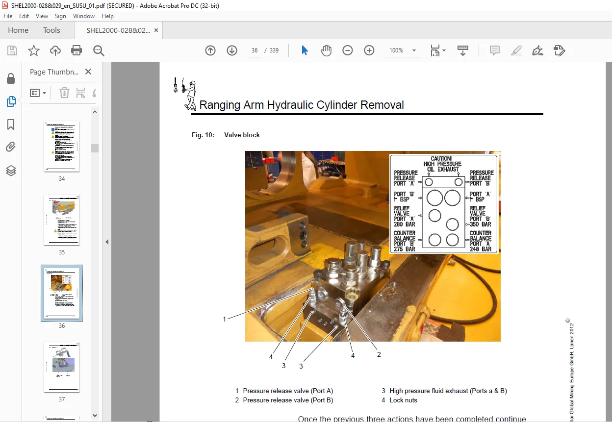
Ranging Arm Hydraulic Cylinder Removal 3.10
Ranging Arm Hydraulic Cylinder Removal 3.10
Removal of the cylinder 3.10
Valve Block Removal Procedure 3.11
Cylinder Anchor Pin Removal Procedure 3.14
Cylinder Clevis Pin Removal Procedure 3.15
EL68A Ranging Arm Motor Removal 3.17
RA0750 Ranging Arm Removal 3.18
DD100 Haulage Downdrive Removal 3.20
Haulage Motor Removal 3.22
HU150 Haulage Unit Removal 3.23
EL56BN Hydraulic Power Pack Motor Removal 3.25
Hydraulic Power Pack Removal 3.26
Caterpillar Global Mining Europe GmbH, Lünen 2012E
Table of content
EL2000 Shearer
Control Box (EL49A), Power Box (EL48A) Removal 3.28
Mainframe 3.30
Shoepost/Skid Shoe Removal 3.32
Shoepost Removal 3.32
Shoepost Assembly 3.32
Valve Block Assembly Procedure 3.36
4. Installation
Installation of the machine underground 4.3
Greasing 4.4
Oil and Fluid filling 4.4
Commissioning the Haulage System 4.5
Fault Diagnosis and Repair 4.6
5. Operation
Introduction To Electrical Equipment 5.3
General 5.3
Electrical control boxes 5.4
Electric motor driven units 5.4
Hydraulically actuated units 5.5
Other electrical equipment 5.5
EL49A Control box 5.9
General 5.9
EL48A Power box 5.13
General 5.13
Operator Controls (electrical) 5.15
Main Switch Handle 5.17
Machine ‘START’ pushbutton 5.17
Motors START / STOP pushbutton 5.17
Motors “STOP” pushbutton 5.17
AFC STOP pushbutton 5.17
Circuit earth leakage test pushbutton 5.18
Earth leakage circuits reset pushbutton 5.18
Stop / Emergency stop lever 5.18
Keypad 5.18
Radio control selection 5.18
Haulage system circuit breaker handle 5.18
Pilot circuit 5.19
General 5.19
Pilot circuit 5.20
Electrical power distribution 5.23
General 5.23
Main power distribution 5.24
Control power distribution 5.25
Caterpillar Global Mining Europe GmbH, Lünen 2012E
Table of content
Doc. no.: EL2000 028 & 029 SUSU / 01
EL68A Ranging Arm Motors 5.29
General 5.30
System operation 5.31
Motor start circuits 5.33
Quill Shaft 5.34
Removal Procedure 5.35
Assembly Procedure 5.38
Quill Shaft Lubrication 5.41
Motor Bearings Lubrication 5.41
EL56BN Power Pack Motor 5.43
General 5.43
System operation 5.44
Motor start circuit 5.45
Lubrication 5.46
Haulage Motor 5.47
General 5.47
Motor operation 5.48
Motor start circuit 5.48
Motor removal procedure 5.48
Lubrication 5.50
Quill Shaft 5.51
Removal Procedure 5.52
Assembly Procedure 5.56
Lubrication 5.58
Radio Control System (Pempek) 5.59
General 5.59
Hydraulic Functions (electrical control) 5.63
General 5.63
Haulage System (AC drive) 5.67
General Description 5.67
Basic System Operation 5.67
AC Haulage Drive(s) 5.68
Configuration Switches 5.69
Double Drive Operation 5.71
Parameters 5.71
Regeneration 5.71
Haulage Circuit Description 5.71
Component Location (quick reference guide) 5.75
General 5.75
Maintenance (electrical) 5.85
Maintence schedules 5.86
General machine specification 5.91
Hoses 5.93
Abbreviations 5.93
Operator controls (mechanical & electrical) 5.94
Electrical Supply 5.94
Machine controls 5.94
Caterpillar Global Mining Europe GmbH, Lünen 2012E
Table of content
EL2000 Shearer
Control mode selector switch 5.94
Cooling supply 5.94
Emergency stop switch and buttons 5.94
Face conditions 5.95
Stopping the shearer 5.95
Electrical trips 5.95
Shearer Operators Report 5.96
Mainframe 5.97
Mainframe Tie Bar Assembly Procedure 5.102
Ranging Arm Hinge Points 5.107
HU 150 Haulage unit 5.109
General 5.109
Downdrive system (DD100) 5.116
Drive Quill Shaft Removal/Assembly 5.119
Lubrication 5.121
Ranging arm RA0750 5.122
Introduction 5.122
General 5.122
High speed section 5.122
Drum speed 5.122
Seals 5.122
Coolers 5.122
Ranging arm lifting cylinder 5.126
Fit ranging arm to mainframe 5.127
Lubrication 5.133
Power pack & hydraulic system 5.135
INTRODUCTION 5.135
General 5.135
Hydraulic Reservoir 5.135
Hydraulic Fluid Cooling 5.136
Pressure Filter 5.137
Return Line Filter 5.137
Safety Relief Valve 5.137
HYDRAULIC PUMP 5.138
DIRECTIONAL CONTROL VALVE BANK 5.138
Solenoid Valve 5.141
RANGING ARM LIFTING CYLINDER (Fig. 167) 5.141
BRAKE VALVE 5.143
HYDRAULIC SYSTEM TECHNICAL DATA 5.144
LUBRICATION 5.145
Water System 5.147
Introduction 5.147
Fire Fighting 5.147
Reverse Flush Filter 5.147
Cooling System 5.148
Caterpillar Global Mining Europe GmbH, Lünen 2012E
Table of content
Doc. no.: EL2000 028 & 029 SUSU / 01
Maintenance (mechanical) 5.151
Introduction 5.151
Oil and Fluid Condition Monitoring 5.152
Maintenance schedules 5.155
6. Technical data
Permissible Media 6.3
General 6.3
Shearer lubrication 6.4
Gear oil filling 6.4
Lubricants 6.5
Gear Oil 6.5
Hydraulic Fluid 6.5
Quill Shaft Grease 6.6
Electric Motor Bearing Grease 6.6
All Other Grease Applications 6.7
Viton Oil Seals 6.8
Torque table 6.9
Torque table 6.10
SUPERNUT tensioning system 6.10
Electrical diagrams 6.11
Diagram Identification 6.11
Balloon Mapping Instructions 6.11
Relay Mapping Instructions 6.11
Wire Number Color Code 6.11
Wire Numbering and Color Coding 6.12
Standing Instructions 6.12
Plug and Socket Details 6.12
Electrical Diagrams 6.13
Hydraulic & water diagrams 6.15
Diagrams 6.15
RECOMMENDED LUBRICANTS 6.17
Electrical diagrams schematic EL2000 S 22 A 6.18
Electrical diagrams schematic EL2000 S 22 B 6.19
Electrical diagrams schematic EL2000 S 22 C 6.20
Electrical diagrams schematic EL2000 S 22 D 6.21
Electrical diagrams schematic EL2000 S 22 E 6.22
Electrical diagrams schematic EL2000 S 22 F 6.23
Electrical diagrams wiring EL2000 W 22 A 6.24
Electrical diagrams wiring EL2000 W 22 B 6.25
Electrical diagrams wiring EL2000 W 22 C 6.26
Electrical diagrams wiring EL2000 W 22 D 6.27
Electrical diagrams wiring EL2000 W 22 E 6.28
Electrical diagrams wiring EL2000 W 22 F 6.29
Electrical diagrams wiring EL2000 W 22 G 6.30
Caterpillar Global Mining Europe GmbH, Lünen 2012E
Table of content
EL2000 Shearer
7. For your information
Our service 7.3
Europe 7.3
Standards and guidelines 7.4
Referenced European standards and guidelines 7.4
Referenced USA standards and guidelines 7.4
Referenced Australian standards and guidelines 7.4
ANNEXE 7.5
Hydraulic, Water and Lubrication diagrams 7.5
SUPERNUT (Downdrive) 7.5
P & S Expansion Bolt System (Shoepost) 7.5
Clampex clamping set 7.5
AmerCable Trailing Cable 7.5
Pempek Radio System 7.5
Rocol Dry Moly Paste 7.5
ACT Cable Handler 7.5
Caterpillar Global Mining Europe GmbH, Lünen 2012E
1
S.M 27/3/2025