Cat Electric Rope Shovel Sullair ES-6 Series User Manual – PDF DOWNLOAD
Original price was: $80.00.$27.95Current price is: $27.95.
CAT Electric Rope Shovel 7295 49HR 495HF2 295HR 141367 141461 – Sullair ES-6 Series – BI619898 – 02250173-918-R00x – MD6640 7495HF 1 Operation & Maintenance Manuals EN PDF
Description
Cat Electric Rope Shovel Sullair ES-6 Series User Manual – PDF DOWNLOAD
DESCRIPTION:
Cat Electric Rope Shovel Sullair ES-6 Series User Manual – PDF DOWNLOAD
1.1 GENERAL
- Sullair Corporation and its subsidiaries design and manufacture all of their products so they can be operated safely. However, the responsibility for safe operation rests with those who use and maintain these products.
- The following safety precautions are offered as a guide which, if conscientiously followed, will mmImIze the possibility of accidents throughout the useful life of this equipment.
- The compressor should be operated only by those who have been trained and delegated to do so, and who have read and understood this Operator’s Manual. Failure to follow the instructions, procedures and safety precautions in this manual may result in accidents and injuries. NEVER start the compressor unless it is safe to do so.
- DO NOT attempt to operate the compressor with a known unsafe condition. Tag the compressor and render it inoperative by disconnecting and locking out all power at source or otherwise disabling its prime mover so others who may not know of the unsafe condition cannot attempt to operate it until the condition is corrected.
- Install, use and operate the compressor only in full compliance with all pertinent OSHA regulations and/or any applicable Federal, State, and Local codes, standards and regulations.
- DO NOT modify the compressor and/or controls in any way except with written factory approval. While not specifically applicable to all types of compressors with all types of prime movers, most of the precautionary statements contained herein are applicable to most compressors and the concepts behind these statements are generally applicable to all compressors.
1.2 PERSONAL PROTECTIVE EQUIPMENT
Prior to installing or operating the compressor, owners, employers and users should become familiar with, and comply with, all applicable OSHA regulations and/or any applicable Federal, State and Local codes, standards, and regulations relative to personal protective equipment, such as eye and face protective equipment, respiratory protective equipment, equipment intended to protect the extremities, protective clothing, protective shields and barriers and electrical protective equipment, as well as noise exposure administrative and/or engineering controls and/or personal hearing protective equipment
1.3 PRESSURE RELEASE
A. Install an appropriate flow-limiting valve between the service air outlet and the shut-off (throttle) valve, either at the compressor or at any other point along the air line, when an air hose exceeding 1/2″ (13mm) inside diameter is to be connected to the shut-off (throttle) valve, to reduce pressure in case of hose failure, per OSHA Standard 29 CFR 1926.302(b )(7) and/or any applicable Federal, State and Local codes, standards and regulations.
B. When the hose is to be used to supply a manifold, install an additional appropriate flow-limiting valve between the manifold and each air hose exceeding 1/2″ (13mm) inside diameter that is to be connected to the manifold to reduce pressure in case of hose failure.
C. Provide an appropriate flow-limiting valve at the beginning of each additional 75 feet (23m) of hose in runs of air hose exceeding 1/2″ (13mm) inside diameter to reduce pressure in case of hose failure.
D. Flow-limiting valves are listed by pipe size and rated CFM. Select appropriate valves accordingly, in accordance with their manufacturer’s recommendations.
E. DO NOT use air tools that are rated below the maximum rating of the compressor. Select air tools, air hoses, pipes, valves, filters and other fittings accordingly. DO NOT exceed manufacturer’s rated safe operating pressures for these items.
F. Secure all hose connections by wire, chain or other suitable retaining device to prevent tools or hose ends from being accidentally disconnected and expelled.
G. Open fluid filler cap only when compressor is not running and is not pressurized. Shut down the compressor and bleed the sump (receiver) to zero internal pressure before removing the cap.
H. Vent all internal pressure prior to opening any line, fitting, hose, valve, drain plug, connection or other component, such as filters and line oilers, and before attempting to refill optional air line anti-icer systems with antifreeze compound.
I. Keep personnel out of line with and away from the discharge opening of hoses or tools or other points of compressed air discharge.
J. Use air at pressures less than 30 psig (2.1 bar) for cleaning purposes, and then only with effective chip guarding and personal protective equipment per OSHA Standard 29 CFR 1910.242 (b) and/or any applicable Federal, State, and Local codes, standards and regulations.
K. DO NOT engage in horseplay with air hoses as death or serious injury may result.
TABLE OF CONTENTS:
Cat Electric Rope Shovel Sullair ES-6 Series User Manual – PDF DOWNLOAD
SECTION 1 = SAFETY
1 1 1 GENERAL SAFETY
1 1 2 PERSONAL PROTECTIVE EQUIPMENT
1 1 3 PRESSURE RELEASE
2 1 4 FIRE AND EXPLOSION
2 1 5 MOVING PARTS
3 1 6 HOT SURFACES, SHARP EDGES AND SHARP CORNERS
3 1 7 TOXIC AND IRRITATING SUBSTANCES
3 1 8 ELECTRICAL SHOCK
4 1 9 LIFTING
4 1 10 ENTRAPMENT
SECTION 2 = DESCRIPTION
5 2 1 INTRODUCTION
5 2 2 DESCRIPTION OF COMPONENTS
5 2 3 ENCAPSULATED COMPRESSOR SYSTEM,
FUNCTIONAL DESCRIPTION
7 2 4 COMPRESSOR COOLING SYSTEM,
FUNCTIONAL DESCRIPTION
7 2 5 AIR INLET SYSTEM, FUNCTIONAL DESCRIPTION
7 2 6 CONTROL, FUNCTIONAL DESCRIPTION
8 2 7 INSTRUMENTATION, FUNCTIONAL DESCRIPTION
SECTION 3 = SPECIFICATIONS
9 3 1 SPECIFICTIONS – ES-6
CONTINUED
BI619898
TABLE OF CONTENTS
PAGE SECTION DESCRIPTION
SECTION 3 – SPECIFICATIONS (CONTINUED)
COMPRESSOR LUBRICATION GUIDE
COMPRESSOR LUBRICATION GUIDE –
24KT COMPRESSORS
3 4 LUBRICATION GUIDE – OPTIONAL FLUID
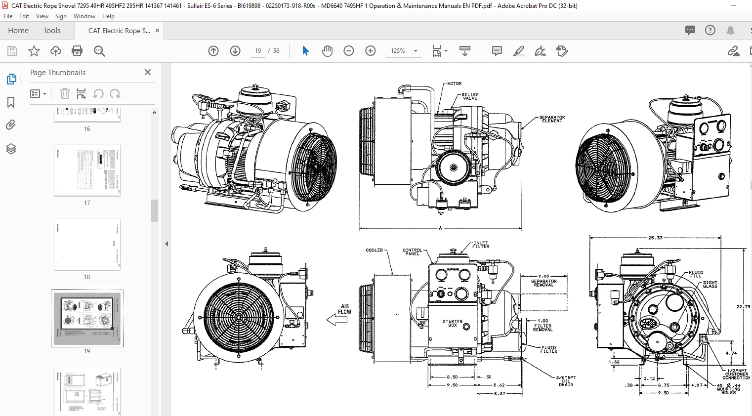
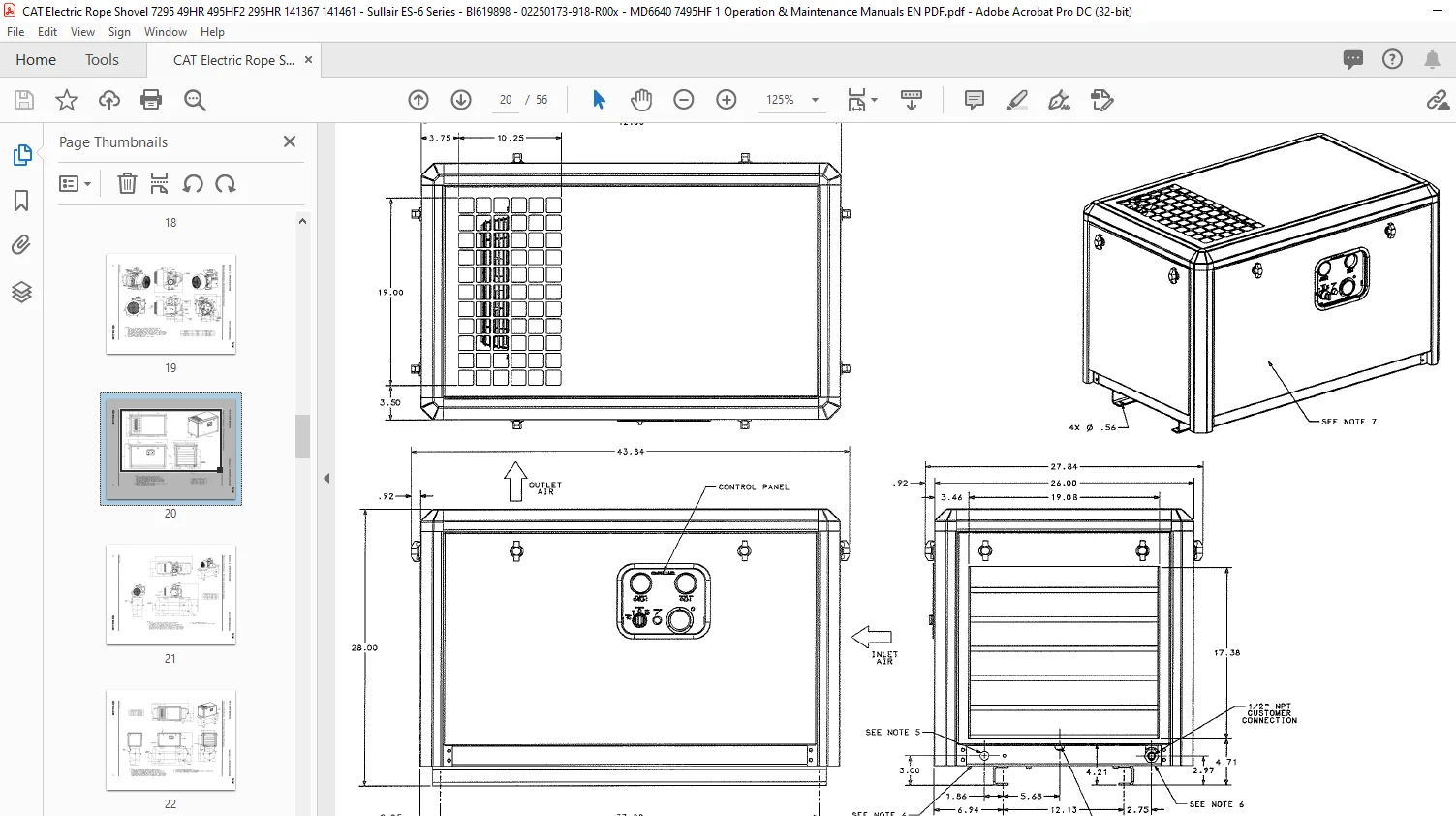
Figure 3-2 Identification – ES-6 Standard without Enclosure
Figure 3-3 Identification – ES-6 Standard with Enclosure
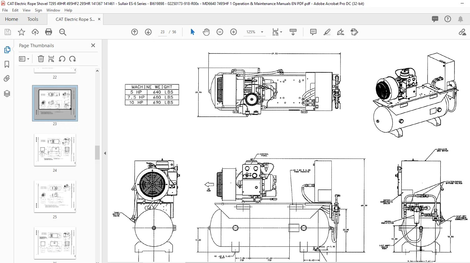
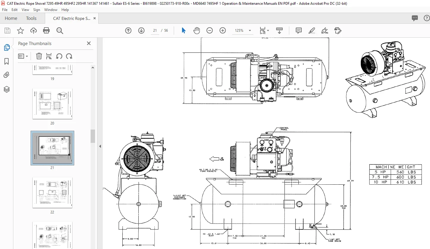
Figure 3-4 Identification – ES-6 Open Tank Mount (80 Gallon)
Figure 3-5 Identification – ES-6 Enclosed Tank Mount (80 Gallon)
Figure 3-6 Identification – ES-6 Open Tank Mount (80 Gallon) with Dryer
Figure 3-7 Identification – ES-6 Enclosed Tank Mount (80 Gallon) with Dryer
Figure 3-8 Identification – ES-6 Open Tank Mount (120 Gallon)
Figure 3-9 Identification – ES-6 Enclosed Tank Mount (120 Gallon)
Figure 3-10 Identification – ES-6 Open Tank Mount (120 Gallon) with Dryer
Figure 3-11 Identification – ES-6 Enclosed Tank Mount (120 Gallon) with Dryer
Figure 3-12 Piping and Instrumentation Diagram – Standard and Wye-Delta
Figure 3-13 Wiring Diagram – Dual Control Full Voltage 2-Wire
Figure 3-14 Wiring Diagram – Dual Control Full Voltage 3-Wire
Figure 3-15 Wiring Diagram – Dual Control 200-230/1/60 5HP
Figure 3-16 Wiring Diagram – Dual Control Wye-Delta
Figure 3-17 Wiring Diagram – SRS 25-100 115-230V/1/60
Figure 3-18 Wiring Diagram – SRS 9-18 220-240V/1/50
Figure 3-19 Wiring Diagram – SRS 24-30 220-240V/1/50
SECTION 4 – INSTALLATION
33 4 1 LOCATION OF COMPRESSOR
33 4 2 VENTILATION AND COOLING
33 4 3 SERVICE AIR PIPING
33 4 4 FLUID LEVEL CHECK AND CHANGE PROCEDURE
33 4 5 MOTOR ROTATION DIRECTION CHECK
33 4 6 ELECTRICAL PREPARTATION
SECTION 5 – OPERATION
35 5 1 GENERAL
~SULLAIR
BI619898
TABLE OF CONTENTS
PAGE SECTION DESCRIPTION
SECTION 5 = OPERATION (CONTINUED)
PURPOSE OF CONTROLS
INITIAL START-UP PROCEURE
SUBSEQUENT START-UP PROCEDURE
SHUTDOWN PROCEDURE
SECTION 6 – MAINTENANCE
37 6 1 GENERAL
37 6 2 DAILY OPERATION
37 6 3 MOTOR BEARNING LUBRICATION
38 6 4 FLUID FILTER MAINTENANCE
38 6 5 COOLER MAINTENANCE
38 6 6 PARTS REPLACEMENT AND ADJUSTMENT PROCEDURES
38 FLUID FILTER REPLACEMENT
39 AIR FILTER MAINTENANCE
39 SEPARATOR ELEMENT REPLACEMENT
40 MINIMUM PRESSURE/CHECK VALVE MAINTENANCE
40 THERMOSTAT ACTUATOR MAINTENANCE
41 CONTROL SYSTEM ADJUSTMENT
41 PRESSURE SWITCH ADJUSTMENT
41 PRESSURE REGULATOR ADJUSTMENT
42 FOR DIFFERENTIAL ADJUSTMENT OF AIR
PRESSURE SWITCH
42 UNLOADER SOLENOID VALVE MAINTENANCE
42 INLET CONTROL VALVE
44 MOTOR SHAFT SEAL REPLACEMENT
44 6 7 TROUBLESHOOTING
44 6 8 TROUBLESHOOTING GUIDE
46 6 9 MAINTENANCE RECORD
SECTION 7 = MAINTENANCE PARTS LIST
PROCUDURE FOR ORDERING PARTS
RECOMMENDED SPARE PARTS LIST
CAT ELECTRIC ROPE SHOVEL SULLAIR ES-6 SERIES USER MANUAL – PDF DOWNLOAD:
IMAGES PREVIEW OF THE MANUAL:


PLEASE NOTE:
- This is the SAME MANUAL used by the dealerships to diagnose your vehicle
- No waiting for couriers / posts as this is a PDF manual and you can download it within 2 minutes time once you make the payment.
- Your payment is all safe and the delivery of the manual is INSTANT – You will be taken to the DOWNLOAD PAGE.
- So have no hesitations whatsoever and write to us about any queries you may have : heydownloadss @gmail.com
S.M