
Cat MD6290 Rotary Drill SKS-W Infinity Blasthole Drill Service Manual SN 1A66K19 – PDF DOWNLOAD
Original price was: $97.95.$38.95Current price is: $38.95.
Cat MD6290 Rotary Drill SKS-W Infinity Blasthole Drill Service Manual SN 1A66K19 – PDF DOWNLOAD
Description
Cat MD6290 Rotary Drill SKS-W Infinity Blasthole Drill Service Manual SN 1A66K19 – PDF DOWNLOAD
CAT MD6290 ROTARY DRILL SKS-W INFINITY BLASTHOLE DRILL SERVICE MANUAL SN 1A66K19 – PDF DOWNLOAD:
IMAGES PREVIEW OF THE MANUAL:


DESCRIPTION:
Cat MD6290 Rotary Drill SKS-W Infinity Blasthole Drill Service Manual SN 1A66K19 – PDF DOWNLOAD
PARTS ORDERING AND PRODUCT SUPPORT :
Use only genuine Bucyrus parts in the maintenance, rebuild or repair of these machines. The manufacturer shall have no liability as to any unauthorized modification of machines or parts. The manufacturer is also not obligated or liable for a machines or parts that have been improperly handled; that have not been operated, maintained or repaired according to furnished manuals or other written instructions, and that have been operated with other than genuine Bucyrus parts or authorized OEM components.
IDENTIFICATION OF THE MACHINE
Always furnish the Model Number and Serial Number when ordering parts. This information is found on the machine nameplate.
PART NUMBER AND DESCRIPTION
In addition to the Model and Serial Number, always give the part number and description of each part ordered. If there is any doubt as to the correct part number and description, furnish a dimensioned sketch or return the part to be replaced, transportation charges prepaid.
SHIPMENT
Unless otherwise instructed, all shipments will be made via motor freight collect, freight forwarder or UPS prepaid and charged on our invoice. Shipments cannot be made on open account until your credit has been approved by our accounting department.
Safety Information :
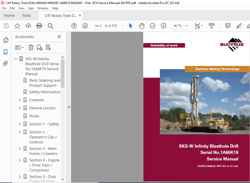
This manual is furnished with your Infinity Series rotary blasthole drill to aid you in performing the necessary service work to maintain your drill in good operating condition. This manual contains repair and adjustment information for all major operating systems on the machine. In some cases such as hydraulic pumps and motors it is better to replace the unit with a new or rebuilt unit than to perform major repairs. Should further information be desired or should particular problems arise which are not covered sufficiently in this manual, the matter should be referred to manufacturer.
- The descriptions and specifications contained in this manual were in effect at the time of printing. The right is reserved to make changes at any time without notice and without obligation. It is YOUR responsibility to understand and follow manufacturer’s instructions on machine operation and service, and to observe pertinent safety precautions, laws and regulations. Failure to read and understand this manual and all safety, capacity and instruction placards on the machine before operating the unit, constitutes a misuse of the machine.
- It is your responsibility to know the manufacturer’s specific requirements, government regulations, required precautions and any work hazards which may exist. You must make these known to all personnel working with the equipment or in the area, so that all may take the necessary and required safety precautions.
- Keep all children, visitors, and untrained personnel away from the equipment. It is also your responsibility to operate your equipment with skill, good judgment, and caution. Following recognised safety procedures will help you avoid accidents. Failure to heed these instructions can result in property damage, serious injury or death.
TABLE OF CONTENTS:
Cat MD6290 Rotary Drill SKS-W Infinity Blasthole Drill Service Manual SN 1A66K19 – PDF DOWNLOAD
SKS-W Inἀnity Blasthole Drill Serial No.1A66K19 Service Manual..................  2
	Parts Ordering and Product Support..........................................  3
	Safety Information..........................................................  4
	Contents....................................................................  5
		Page Int-5..............................................................  5
		Page Int-6 .............................................................  6
		Page Int-7 .............................................................  7
		Page Int-8..............................................................  8
		Page Int-9..............................................................  9
		Page Int-10............................................................. 10
		Page Int-11............................................................. 11
		Page Int-12............................................................. 12
		Page Int-13............................................................. 13
		Page Int-14............................................................. 14
		Page Int-15 ............................................................ 15
		Page Int-16 ............................................................ 16
	General Locator............................................................. 17
		General Locator......................................................... 17
	Notes....................................................................... 19
	Section 1 – Safety.......................................................... 21
		Section 1 Contents...................................................... 23
			Page 1-3............................................................ 23
		Safety.................................................................. 25
			Personal	Protective	Equipment....................................... 25
			Noise............................................................... 25
			Electrical	Contact.................................................. 25
			Overhead	and	Buried	Utilities....................................... 25
			Contact	with	Electric	Wires......................................... 26
			Contaminated Air.................................................... 26
			Machine	Stability................................................... 27
			Moving	and	Rotating	Parts........................................... 28
			High	Pressure	Air	or	Fluid.......................................... 28
			Before	Operation.................................................... 28
			During	Operation.................................................... 29
			Maintenance......................................................... 31
			Safety Locator...................................................... 32
		Notes................................................................... 34
	Section	2 - Operator's Cab / Controls....................................... 35
		Section 2 Contents...................................................... 37
			Page 2-3............................................................ 37
		Graphic	Symbol	Legend................................................... 39
			Graphic	Symbol	Legend............................................... 39
		Warning Decals.......................................................... 43
			Warning	Decals...................................................... 43
		Operator Control and Instrument Panels.................................. 45
			Operator Control Panel.............................................. 45
			System	Pressure	Gauge	Panel......................................... 50
			Switch	Panel........................................................ 51
			Switches	/	Diagnostic	/	Control	Panel	Circuit....................... 54
		Cab Heater.............................................................. 56
			Cab	Heater	Fault	Isolation.......................................... 56
		Air Conditioner......................................................... 57
			T7	Series	Split	System	Air	Conditioning	Manual...................... 57
			Section		1.0	Technical	Data	and	Control	Settings.................... 58
			Section	2.0	Installation	and	Commissioning.......................... 60
			Section	3.0	Routine	Maintenance	Procedures.......................... 66
			Section	4.0	Fault	Diagnosis......................................... 67
			Section		5.0	Reference	Drawings	.................................... 76
		Notes................................................................... 81
	Section 3 - Main Frame / Crawlers........................................... 83
		Contents................................................................ 85
			Page 3-3............................................................ 85
			Page 3-4............................................................ 86
		Main Frame Repair - General............................................. 87
			Main Frame Repair................................................... 87
		Weld Inspection Schedule................................................ 88
			Main Frame.......................................................... 88
		Levelling Jacks......................................................... 89
			Levelling	Jack	Cylinder............................................. 89
			Levelling	Jacks..................................................... 90
			Limit	Switch........................................................ 90
			Levelling	Jack	Cylinders............................................ 90
		Mast Elevating Cylinders................................................ 91
			Mast	Elevating	Cylinders............................................ 91
			Internal	Counterbalance	Valve....................................... 92
		Crawler Assembly........................................................ 94
			Crawler	Assembly.................................................... 94
			Parts List.......................................................... 95
			Crawler Component Repair............................................ 95
		Metric Bolt Torque Specifcations........................................ 96
			Metric	Bolt	Torque	Specification.................................... 96
		Track Tension Adjustment................................................ 97
			Before	Operating	the	Machine:....................................... 97
			General Maintenance................................................. 97
			Track	Assembly...................................................... 98
			Idler Unit Description.............................................. 99
			Hydraulic Tensioner.................................................100
			Nitrogen	Tensioner..................................................101
			Nitrogen	Tensioner	–	 Filling	Instructions..........................102
			Nitrogen	Tensioner	–	Pressure	Check.................................103
			Nitrogen	Tensioner	–	Pressure	Release...............................103
		Hydraulic Tensioner.....................................................104
			Hydraulic	Tensioner	Assembly........................................104
			Repair..............................................................104
		Track Chain.............................................................105
			Track	Chain	–	Separate..............................................105
			Track	Chain	Repair..................................................106
		Track Shoes Installation................................................108
			Track	Link	Position.................................................108
			Track	Shoe	–	Mounting	to	Track	Chain................................108
		Track Shoe Bolt Torque (Direct Torque Method)...........................110
			Bolt	Torque	KN111...................................................110
		Track Shoe Bolt Torque (Torque Turn Method).............................111
			Bolt	Torque	KN111...................................................111
		Track Chain and Shoe Installation.......................................112
			Track	Chain	with	Shoes..............................................112
			Track	Chain	and	Shoe	–	Assembly	and	Installation....................112
		Final Drive Unit........................................................114
			General Description.................................................114
			Removal	from	Track	Frame............................................115
			Installation	into	Track	Frame.......................................116
			Final	Drive	Maintenance.............................................117
			Final	Drive	Oil.....................................................118
			Final	Drive	Assembly................................................119
			Parts List..........................................................120
			Final Drive –	Disconnect and Parking Brake..........................121
			Towing	Procedure	–	Gear	Drive	Disconnect............................121
			Parking	Brake	–	Description.........................................122
			Parking	Brake	–	Removal	and	Installation............................122
		Idler Unit..............................................................123
			Idler	Unit	–	Assembly...............................................123
			Idler	Unit	–	Removal................................................126
		Track and Support Rollers...............................................127
			Track	Roller	Assembly...............................................127
			General Description.................................................127
			Track	Roller	–	Removal	and	Disassembly..............................128
			Support	Roller	–	Removal	and	Disassembly............................128
			Track	and	Support	Roller	–	Assembly.................................129
			Track	and	Support	Roller	–	 Test and Install........................130
		Track and Sprocket Inspection...........................................132
			Track	Inspection	and	Wear	Limit	Guide...............................132
			Sprocket	Wear	Patterns..............................................136
		Auxiliary Crane.........................................................142
			Hydraulic	Crane	(Auxiliary	Crane)...................................142
			Maintenance.........................................................143
			Checking	of	Worm	Gear...............................................143
		Notes...................................................................144
	Section 4 - Engine / Drive Train / Compressor...............................145
		Section Contents........................................................147
			Page 4-3............................................................147
			Page 4-4............................................................148
		Power Group Locator.....................................................149
			Power Group Locator.................................................149
		Test Point Locator......................................................150
			Test Point Locator..................................................150
		Caterpillar C27 Engine..................................................152
			Caterpillar C27 Engine..............................................152
			Engine Mounts – Installation........................................153
		Engine and Compressor Air Cleaners......................................154
			Engine and Compressor Air Cleaner Service Assembly..................154
			Engine and Compressor Air Cleaner Service...........................155
		Flexible Drive Coupling.................................................158
			Flexible Drive Coupling Service.....................................158
		Pump Drive..............................................................160
			Pump Drive Assembly.................................................160
			Pump Drive Assembly – Removal and Replacement.......................161
		Pump Drive Gearbox......................................................162
			Pump Drive Gearbox..................................................162
			Pump Drive Gearbox – Repair.........................................163
			Pump Drive Gear Box Input Shaft Assembly............................164
		Hydraulic Pumps.........................................................166
			Hydraulic Pumps – Removal and Replacement...........................166
		Compressor Installation.................................................167
			Safety..............................................................167
			Compressor Installation.............................................170
			Compressor Drive Coupling...........................................172
			Compressor Alignment................................................173
		Compressor Shaft Seal...................................................174
			Compressor Shaft Seal...............................................174
		Low Pressure Compressor.................................................176
			Description.........................................................176
			Compressed Air Functions............................................176
			Compressor Inlet Valve Control System...............................180
			Inlet Valve.........................................................181
			Compressor Regulation...............................................183
			Relieving Regulators................................................184
			Reducing Regulators.................................................186
			System Blowdown Valve...............................................188
			Running Blowdown Valve..............................................189
			Running Blowdown Maintenance........................................190
			Compressor Air and Oil Circuits - 2000cfm @ 125psi..................191
			Operation...........................................................194
			Compressor Air Circuit Legend.......................................195
			Compressor Control Set-up Vented Poppet Inlet.......................196
		Compressor Maintenance..................................................201
			General Maintenance.................................................201
			Compressor Receiver Tank Assembly...................................202
			Separator Elements..................................................203
			Separator Elements – Remove and Replace.............................204
			Scavenge Line.......................................................205
			Compressor Discharge Temperature Gauge, Switch and Sender...........207
			Thermal Bypass Valve................................................208
			Thermal Bypass Valve Maintenance....................................209
			Compressor Fluid Filter.............................................210
			Changing Filter Elements............................................211
			Troubleshooting.....................................................212
		Coolers.................................................................214
			Hydraulic Oil / Radiator Cooler Assembly............................214
			Compressor Oil Cooler...............................................215
			Fan Speed...........................................................215
		Aluminium Tube Air to Oil Cooler........................................216
			Aluminium Tube Air to Oil Cooler – Standard Parts...................216
			Removal and Replacement.............................................217
			Oil Cooler – Internal Cleaning......................................219
		Radiator Cooler.........................................................221
			Typical Radiator Core – Standard Parts..............................221
			Cleaning............................................................222
			Tube Removal........................................................222
			Seal Installation...................................................223
			Tube Installation...................................................224
		Notes...................................................................226
	Section 5 - Dust Control System.............................................227
		Section 5 Contents......................................................229
			Page 5-3............................................................229
		Dust Control System.....................................................231
			Dust Control Systems................................................231
		Water Injection.........................................................233
			Water Tanks.........................................................233
			Water	Injection	Relief	Valve........................................234
			Water Injection Control.............................................235
			Water Injection Basic Circuit.......................................236
		Water Pump..............................................................237
			Pump	Specification..................................................237
			Servicing	Instructions..............................................237
			Water	Injection	Pump	Assembly.......................................238
			Replacing	Piston	Cup	Seals..........................................239
			Replacing	Suction	and	Discharge	Valves..............................240
			Replacing	Power	End	Bearings........................................241
			Servicing	the	Wrist	Pin	Bearings....................................242
			Fastener Torque Requirements........................................242
			Recommended	Lubricants..............................................243
			Water	Pump	Motor	Repair.............................................243
			Water	Injection	Hydraulic	Control	Valve	Repair......................243
			Water	Pump	Drive	Coupling...........................................243
			Level	and	Flow	Transducer...........................................243
		Notes...................................................................244
	Section 6 - Mast / Rotary Drive / Pipe Rack.................................245
		Section 6 Contents......................................................247
			Page 6-3............................................................247
			Page 6-4 ...........................................................248
		Mast Weldment...........................................................249
			Mast Repair.........................................................249
		Weld Inspection Schedule................................................250
			Inspection Mast.....................................................250
		Mast Assembly and Installation..........................................251
			Mast	Assembly	10m...................................................251
			Mast Weldment.......................................................252
			Mast Pivot..........................................................252
			Mast	Locking........................................................252
			Mast / Drill Without Mast...........................................253
			Mast	Assembly.......................................................254
			Raising	the	Mast....................................................254
		Hoist / Pulldown Cylinder...............................................256
			Hoist / Pulldown Cylinder and Parts List............................256
			Removal from	Mast	Assembly..........................................257
			Repair..............................................................258
			Installation........................................................258
		Hoist / Pulldown Cable..................................................260
			Adjustment..........................................................260
			Replacement.........................................................262
		Rotary Drive............................................................264
			Rotary	Head	Assembly................................................264
			Rotary	Head	Guide	Alignment.........................................265
			Rotary	Head	–	Drive	System..........................................267
			Rotary Drive – Removal from Mast....................................268
			Rotary Drive – Installation.........................................268
			Rotary	Drive	Gearbox	–	Repair.......................................269
			Rotary	Head	Bull	Shaft	Bearing	Nut..................................270
			Manufacturers	Recommendations	–	Blast	Hole	Drilling	Consumables	....271
			Air	Swivel..........................................................272
		Winch Assembly..........................................................273
			Precautions on the Use of Winches...................................273
			Wire Rope...........................................................273
			Wedge	Sockets.......................................................275
			Grooved Drums.......................................................275
			Drums – Multiple Layers.............................................276
			Winch	Assembly	Service..............................................277
			BG8A & BG8B Hydraulic Winch Service Manual..........................278
			Forward.............................................................279
			Explanation	of	Model	Number.........................................279
			Theory of Operation.................................................280
			Winch Installation..................................................282
			Wire Rope Installation..............................................283
			Preventative Maintenance............................................284
			071	Motor...........................................................285
			Troubleshooting.....................................................286
			Disassembly	of	Winch................................................290
			Planetary	Carrier	Service...........................................292
			Motor	Support	Brake	Cylinder	Service................................294
			Brake	Clutch	Service................................................298
			Winch	Assembly......................................................300
			Brake	Valve	Service.................................................302
			Reversing	Direction	of	Drum	Rotation................................304
			Recommended fastener Torque.........................................305
			Metric	Conversion	Table.............................................306
		Deck Wrench.............................................................307
			Deck Wrench.........................................................307
		H.O.B.O Wrench..........................................................308
			H.O.B.O	Wrench......................................................308
			Breakout	System	–	H.O.B.O...........................................309
			Optional	Hydraulic	Operated	Bit	Basket	–	H.O.B.B....................309
		Pipe Positioner.........................................................310
			Pipe Postioner......................................................310
		Carousel Pipe Rack......................................................311
			Major	Components....................................................311
			Rod	Handling	–	Carousal	Indexing....................................312
			Pipe	Rack	Assembly..................................................313
			General Information.................................................314
			Pipe	Rack	Bearings	–	Removal........................................314
			Pipe Rack Components – Inspection...................................316
			Pipe	Rack	–	Assembly	and	Installation...............................317
			Pipe Rack Roller – Remove and Replace...............................318
			Pipe	Rack	Roller	–	Disassembly	and	Assembly.........................319
		Top Sub Saver...........................................................321
			Replacement Procedure...............................................321
		Notes...................................................................322
	Section 7 - Hydraulic Systems...............................................323
		Section 7 Contents......................................................325
			Page 7-3............................................................325
			Page 7-4............................................................326
			Page 7-5............................................................327
		Hydraulic Symbols.......................................................329
			Hydraulic	Symbols...................................................329
		Pressure Setting Sequence...............................................  0
			Pressure	Setting	Sequence...........................................  0
			Hydraulic System....................................................  0
		Hydraulic Tank..........................................................332
			Hydraulic	Tank......................................................332
			Return Hydraulic Filters............................................333
		Main Hydraulic Pumps....................................................334
			Pump	Identificatio..................................................334
		Right Track / Pulldown, Left Track / Rotation Pumps.....................335
			Hydraulic	Piston	Pumps	–	Removal	and	Replacement....................335
			Main Pumps..........................................................335
			EP	(24V	DC)	Control.................................................335
			Linde	HPV-02	Variable	Displacement	Pump.............................336
			Operational Parameters..............................................338
			Linde	HPV-02	Pump	Schematic.........................................339
			Controls............................................................340
			Dimensions..........................................................343
			Charge	Pumps........................................................344
			Setting	Linde	HPV-02	Main	Pumps	–	Neutral		Setting..................345
			Setting	Linde	HPV-02	Main	Pumps	–	Pressure	Settings.................346
			Setting	Linde	HPV-02	Main	Pumps	–	Pre-setup	Checks..................347
			Main	Pumps	Linde	HPV-02.............................................348
			Break	Test	Procedure	SK	Infinit	Series	Drills.......................349
			Setting	Procedure...................................................349
			Charge	Pressure,	High	Pressure,	P.O.R	and	Zero	Position	Settings....351
			Set	Charge	Pressure	–	320psi	(22	bar)...............................351
		Charge Circuit..........................................................352
			Charge	Circuit......................................................352
		Charge Filter...........................................................353
			Routine Maintenance.................................................353
			Changing	Filter	Elements............................................354
		Main Pumps Circuit......................................................355
			Main Pumps Circuit..................................................355
		Main Return and Case Drain Filter.......................................356
			Routine Maintenance.................................................357
			Changing	Filter	Elements............................................357
		Loop Filters............................................................358
			Routine Maintenance.................................................358
			Filter	Assembly	Loop................................................360
			Changing	Filter	Elements............................................361
		Rotation Circuit........................................................362
			Rotation Circuit....................................................362
		Rotary Drive Gearbox Motor..............................................364
			Rotary	Drive	Gearbox	Motor	–	Test	and	Repair........................364
			Rotary	Gearbox	Rotation	Motor.......................................365
			Shaft Seal Replacement..............................................366
			Troubleshooting.....................................................367
		Tram Circuit............................................................369
			Tram Circuit........................................................369
		Main Closed Loop Circuits...............................................371
			Diverter	Valve......................................................371
			Operation...........................................................371
			Diverter	Valve......................................................371
		Left Track / Rotation Pump..............................................372
			Basic	Left	Track	/	Rotation	Pump	Circuit............................372
			Basic	Left	Track	/	Rotation	Pump....................................372
		Right Track / Pulldown and Hoist Circuit................................373
			Basic	Right	Track	/	Pulldown	and	Hoist	Circuit......................373
			Basic	Right	Track	/	Pulldown	and	Hoist..............................373
		Pulldown and Hoist Circuit..............................................374
			Hoist	/	Pulldown	Cylinder	Counterbalance	Valve......................374
		Counterbalance Valves...................................................375
			Counterbalance	Valve	Adjustments....................................375
		Pilot Control Manifold..................................................376
			Pilot Control Manifold..............................................376
			Pilot	Control	Manifold	Assembly.....................................377
			Electro	Proportional	Valves.........................................389
			Proportional	Valve	Set up...........................................390
			Auto Pulldown Card..................................................390
			Proportional Pulldown...............................................391
		Auxiliary Pump Circuit..................................................392
			Spools..............................................................392
			Electro	–	Hydraulic	Kit	(24V	DC)....................................392
			Auxiliary Pump......................................................394
			Auxiliary	Functions.................................................394
			Auxiliary Pump Circuit..............................................395
			Auxiliary Pump Operation............................................397
		Jack Control and Mast Elevating Circuit.................................401
			jack	Control	and	Mast	Elevating	Circuit.............................401
			OEM	Controllers	/	EP	Levers.........................................402
			jack	Control	and	Mast	Elevating	Control	Valve.......................403
		Levelling Jack Cylinders................................................404
			Jack Leg Cylinder...................................................404
			Counterbalance	Valve	Test	Procedure.................................404
		Mast Elevating Cylinders................................................405
			Internal Counterbalance Valve.......................................405
			Internal	Counterbalance	Valve	Test	Procedure........................406
		Hydraulic Operated Breakout Wrench......................................407
			H.O.B.O	Wrench	Circuit..............................................407
			Operation...........................................................408
			Setting	of	H.O.B.O	Sequence	Valves..................................409
			H.O.B.O	Float	Valve.................................................409
		Cooler Fan Circuit......................................................410
			Fan	Motor	Circuit...................................................410
			Basic	Cooler	Fan	Circuit............................................412
			Hydraulic Motor.....................................................413
			Cooler	Fan	Motor	Assembly...........................................415
		Hydraulic Thermostatic Valve............................................417
			Hydraulic Cooler – Thermal Valve....................................417
		Water Injection Circuit.................................................418
			Water	Injection	Circuit.............................................418
			Water	Injection	Valve...............................................419
		Water Pump Motor .......................................................420
			Water Pump Motor Repair information.................................420
			Shaft Seal Repair...................................................421
		Hydraulic Cylinder Repair...............................................424
			Hydraulic Cylinders.................................................424
			General information.................................................425
			H Head..............................................................427
			N Head..............................................................428
			Z	Head..............................................................429
			Z	Head	(Two	Piece)..................................................430
			K Head..............................................................431
			M Head..............................................................432
			Z	Piston............................................................433
			Z	Piston	(Threaded).................................................434
			H and K Piston......................................................435
			M Piston............................................................436
			N Piston............................................................439
		Notes...................................................................440
	Section	8	-	Electrical	Components...........................................441
		Section 8 Contents......................................................443
			Page 8-3............................................................443
		Jump	Starting...........................................................445
			Jump	Starting.......................................................445
		Batteries...............................................................447
			Batteries...........................................................447
		Welding Precautions.....................................................448
			Welding	Precautions.................................................448
		Electrical Components...................................................449
			Electrical Circuits.................................................449
			Transducers.........................................................449
			EP	Levers...........................................................450
			Joystick	Adjustments................................................451
		Vigilante Guide.........................................................453
			Important Information...............................................453
			PLC.................................................................454
			Touchscreen.........................................................457
			Laser	Depth	System..................................................458
			Start	Up	and	Shutdown...............................................461
			Hydraulic	Function	Enable...........................................461
			Alarms..............................................................461
			Solenoid	Control....................................................462
			Auto	Lube...........................................................464
			Gauges..............................................................464
			Level	Switches......................................................466
			Dust	Suppression....................................................466
			Acknowledgements....................................................467
			Disclaimers.........................................................467
		Vendor Documents........................................................443
			8 Channel Analog Card (PLC) ........................................  0
			16 Channel Analog Card (PLC)........................................  0
			32 Digital Input Card ..............................................  0
			Access Light Timer..................................................  0
			Calibrating Laser Depth System......................................  0
			CF Card Download....................................................  0
			Head Speed Flowmeter ...............................................  0
			Inclinometer........................................................  0
			Input and Output Cards..............................................  0
			Ladder Prox Switch..................................................  0
			LDm41A Laser Manual.................................................  0
			Level Switch........................................................  0
			Pico Angle Sensor...................................................  0
			Pressure Transducers................................................  0
			Processor Card .....................................................  0
			Rod Counter Prox Switch.............................................  0
			Touchscreen Installation (GP2500) ..................................  0
			Touchscreen Manual (GP2500).........................................  0
			Using a EEPROM .....................................................  0
			Water Flow Transducer...............................................  0
		Notes...................................................................468
	Section 9 - Lubrication and Preventive Maintenance..........................469
		Section 9 Contents......................................................471
			Page 9-3............................................................471
			Page 9-4............................................................472
		Central Lube System.....................................................473
			Auto	Lube	Basic	Operation...........................................473
			Central	Lube	Tank	Assembly..........................................474
			Auto	Lube	Grease	Pump...............................................475
			Auto Lube Tube Pump.................................................480
			Graco Vent Valve....................................................484
			Central	Lube	System	Circuit.........................................485
			Basic	Operating	Principles	of	Auto	Lube	Injectors...................486
			SL-V	and	SL-V	XL	Injectors..........................................486
			SL-1	and	SL-11	Injectors............................................487
			SL-32	Injectors.....................................................488
			Typical	Grease	System	Circuit.......................................489
			First	50	Hour	Service...............................................490
			Lube	Faults	/	Operation.............................................491
			Auto Lube Timer.....................................................492
			Lube	Pressure	Screen................................................492
		Air Service Units.......................................................493
			Filter	Regulator....................................................493
			Air Line Oiler......................................................494
			Soft	Start	Dump	Valve...............................................495
			Air	Service	Unit....................................................496
		Pipe	Thread	Lubricator..................................................497
			Air Operated Pipe Thread Pump.......................................497
		Filter Locator..........................................................505
			Filter	Locator	Assembly.............................................505
		Lubrication and Preventive Maintenance..................................506
			General Lubrication.................................................506
			Equipment	Lubrication...............................................506
			Care	of	Lubrication	Points..........................................506
			Safety..............................................................507
			Track Gear..........................................................508
			Engine	Maintenance..................................................509
			Air	Cleaners........................................................510
			Air	Filter	Elements.................................................510
			Alternator Maintenance..............................................510
			Pump	Drive	and	Drive	Shaft	Maintenance..............................511
			Compressor	Maintenance..............................................511
			Cooler	Packs........................................................511
			A-frame	and	Pivot	Point	Maintenance.................................513
			Pull	Down	and	Hoist	Ropes	and	Sheaves	Maintenance...................513
			Rotary	Head	Maintenance.............................................513
			Hydraulic	System	Maintenance........................................515
			Hydraulic	Maintenance...............................................515
			Water Pump Maintenance..............................................515
			Cab Maintenance.....................................................515
			Air Conditioner Maintenance.........................................517
			Battery Maintenance.................................................517
			Lubrication	System	Maintenance......................................517
			Fire	Suppression	Maintenance........................................517
			Drill	Folding	Stairway	–	Inspection	Requirements....................519
		Weld	Inspection	Schedule................................................520
			Weld	Inspection	Schedule	SK	Series..................................520
		Track and Sprocket Inspection...........................................521
			Track	Inspection	and	Wear	Limit	Guide...............................521
			Sprocket	Wear	Patterns..............................................525
		Lubrication Recommendations.............................................531
			Lubrication	Recommendations.........................................531
		Lubrication	and	Maintenance	Chart	-	250hr...............................532
		Lubrication	and	Maintenance	Chart	-	500hr...............................540
		Lubrication	and	Maintenance	Chart	-	1000hr..............................547
		Lubrication	and	Maintenance	Chart	-	2000hr..............................556
		Lubricant	Specifcations.................................................566
			Hydraulic	System....................................................566
			Hydraulic	Tank	Capacity.............................................566
			Compressor	Lubrication..............................................567
			Compressor	Lubricant	Specification..................................567
			Lubricating	Grease..................................................568
			Gear Lubricant......................................................568
			Scheduled	Oil	Sampling	Analysis.....................................568
		Torque	Values	for	Split	Flange	Connections..............................569
			Torque	Values	for	Split	Flange	Connections..........................569
				Procedure	No.	1-87	Revision	A......................................571
		Notes...................................................................572
PLEASE NOTE:
- This is the same manual used by the DEALERSHIPS to SERVICE your vehicle.
- The manual can be all yours – Once payment is complete, you will be taken to the download page from where you can download the manual. All in 2-5 minutes time!!
- Need any other service / repair / parts manual, please feel free to contact us at heydownloadss @gmail.com . We may surprise you with a nice offer
S.V