Cat Rotary Track Drill 49 -Rll Diesel/Electric Blast Hole Drill OPERATOR’S MANUAL – PDF DOWNLOAD
Original price was: $80.00.$27.95Current price is: $27.95.
Cat Rotary Track Drill 49 -Rll DieselElectric Blast Hole Drill OPERATOR’S MANUAL – PDF DOWNLOAD
Description
Cat Rotary Track Drill 49 -Rll DieselElectric Blast Hole Drill OPERATOR’S MANUAL – PDF DOWNLOAD
DESCRIPTION:
Cat Rotary Track Drill 49 -Rll Diesel/Electric Blast Hole Drill OPERATOR’S MANUAL – PDF DOWNLOAD
FOREWORD
- This manual establishes guidelines and furnishes general instructions for the operation of the Bucyrus-Erie® 49-RII Diesel/Electric Rotary Blast Hole Drill. The drill consists of three major units; the lower works, the main frame, and the mast.
- The lower works provides a foundation for the main frame and contains most of the necessary components to propel the drill. The main frame is mounted upon the lower works and contains the bailing air compressor and all controls to operate the drill.
- The machinery house encloses most of the main frame. The operator’s cab is located at the rear of the main frame and contains the operator’s station. The mast is mounted to the rear of the main frame and contains the machinery required for handling of the tool string, including the hoist/pulldown machinery and the rotary machinery.
This manual is divided into seven sections:
SECTION 1-Safety Precautions and Prestart Checks
SECTION 2 – Controls-Function and Location
SECTION 3 – Start Up
SECTION 4- General Operation
SECTION 5 – Drilling
SECTION 6 – Shut Down
APPENDICES
CAUTION:
- Before attempting to operate the drill, read this manual completely. Familiarize yourself with the contents of this manual so that you can easily locate particular information when you need it.
- Throughout this manual the words CAUTION, WARNING and NOTE appear in bold face type. CAUTION is preceded by the safety alert symbol A and indicates that injury to personnel could occur if the proper procedures are not followed during operation or maintenance
- . Always read the CAUTION note carefully and use extreme care while performing that particular function. WARNING indicates a possible hazard to the machine or its components if the proper procedures are not followed
- . Whenever the word WARNING appears, special attention should be given to prevent possible equipment damage. NOTE is used to stress a point or to give additional information concerning the procedure being discussed.
- These CAUTION’s and WARNING’s are not all-inclusive. It is impossible for Bucyrus-Erie Company to know, evaluate, and advise maintenance and service personnel in every conceivable way a service operation might be performed and of the resulting possible hazardous consequences of each method. It is therefore extremely important that anyone who uses a service procedure or tool which is not recommended by Bucyrus-Erie Company to first satisfy himself that the service procedure or tool he chooses will not jeopardize his own safety, the safety of others, or cause machine or component damage. Every effort has been made to make this manual as complete and accurate as possible at the time of publication. Bucyrus-Erie Company reserves the right, however, to continually improve its products. Therefore changes to the equipment herein may have been made that are not reflected in this manual.
TABLE OF CONTENTS:
Cat Rotary Track Drill 49 -Rll Diesel/Electric Blast Hole Drill OPERATOR’S MANUAL – PDF DOWNLOAD
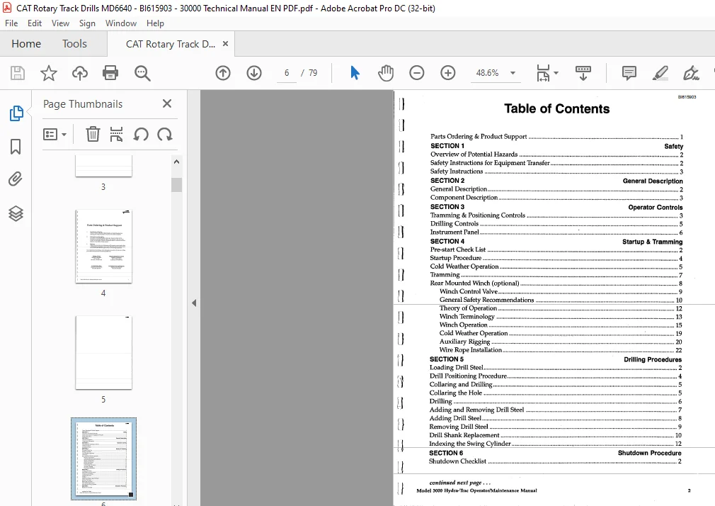
SECTION 1 – SAFETY PRECAUTIONS AND PRESTART CHECKS
SAFETY 1-1
General 1-1
Specific Safety Rules 1-1
Operation Near Electrical Transmission Lines 1-1
PREST ART CHECKS 1-2
OUTSIDE INSPECTION 1-2
ON-BOARD INSPECTION 1-3
PRESTART LUBRICATION 1-5
SECTION 2 – CONTROLS – LOCATION AND FUNCTION
INTRODUCTION 2-1
OPERATOR’S CONSOLE CONTROLS 2-1
MAIN CONTROL PANEL 2-2
Hoist/Pulldown Rheostat 2-2
Rotary Rheostat 2-2
Drill/Propel Controls ON and OFF Pushbuttons 2-2
Hoist/Pulldown Speed Selector Switch 2-2
Rotary Speed Selector Switch 2-3
Hoist Brake Switch 2-3
Pipe Rack Selector Switch 2-3
Pipe Rack Joystick (Left Crawler Propel) 2-3
Winch/Mast Selector Switch 2-3
Mast/Winch Joystick (Right Crawler Propel) 2-3
Tool Wrench Switch 2-4
Dust Curtain Switch 2-4
Bit View Hatch Switch 2-4
PROPEL CONTROL PANEL 2-4
Diesel Emergency Stop Pushbutton 2-4
Propel Speed Selector Switch 2-4
Compressor Stop Pushbutton 2-5
Compressor Vent/Drill Switch 2-5
HeaterNent/Air Conditioner Controls (Optional) 2-5
Operating Mode Selector Switch 2-5
Propel Joysticks 2-5
SELECTOR SWITCHES PANEL 2-5
Breakout Wrench Switch 2-5
Mast Brace Lock Switch 2-5
Mast Lock Switch 2-6
Boarding Stairs Switch 2-6
Ashtray 2-6
Radio (Optional) 2-6
LEVELING CONTROL PANEL 2-6
Manual Leve ling Joysticks 2-6
Automatic Leveling Switch 2-6
Water Injection On/Off Switch (Optional) 2-6
Water Injection Flow Control (Optional) 2-7
Horn Pushbutton 2-7
Depth Indicator Reset Pushbutton 2- 7
Programmed Drill Control Switch 2- 7
PANELVIEW MONITOR 2-7
DIESEL GAUGES PANEL 2-7
BI616762
MACHINERY HOUSE CONTROLS 2-8
Controls Located On Low Voltage Start Cabinet 2-8
Controls Located On Low Voltage Cabinet 2-8
Control Located On Programmable Controller Cabinet 2-9
Hoist/Pulldown and Rotary Drive Control Cabinets 2-9
Controls Located On or Near Screw Type Air Compressor 2-9
Diesel Engine Start Box and Engine Saver Box 2-10
Lube Control Panel 2-10
Diesel Control Box 2-10
Hydraulic Reservoir Remote Fill Control Panel 2-ll
SECTION 3 – START-UP
INTRODUCTION 3-1
MACHINE START-UP 3-1
MACHINERY CHECKS 3-2
BREAK-IN OF NEW COMPONENTS 3-2
Rotary Drive unit Break-In 3-2
Hoist/Pulldown Gearcase Break-In 3-2
Electric Motor Break-In 3-3
SECTION 4 – OPERATION – GENERAL
INTRODUCTION 4-1
PROPELLING 4-1
Towing 4-4
LEVE LING 4-6
MAST RAISING AND LOWERING 4-8
Mast Raising 4-8
Mast Lowering 4-9
PULLDOWN MACHINERY OPERATION 4-10
AUXILIARY WINCH OPERATION 4-ll
PIPE RACK OPERATION 4-ll
TOOL HANDLING 4-13
General Operating Procedure 4-13
Pipe Loading and Unloading 4-13
Drill Tool String Assembly 4-14
Casing Tong Operation 4-18
Drill Tool String Disassembly 4-20
Adding Additional Drill Pipe 4-22
Removal of Multiple Section Drill Pipe 4-23
Dust Suppression System Operation 4-23
SECTION 5 – DRILLING
VERTICAL DRILLING 5-1
General Operating Procedures 5-1
Beginning The Hole (Collaring) 5-1
Normal Drilling 5-2
Ending the Hole (Reaming) 5-3
Ending the Hole (Multiple Pipe Sections) 5-4
DRILLING DIFFICULT FORMATIONS 5-4
Unconsolidated Materials 5-4
Wet or Sticky Formations 5-6
PROGRAMMED DRILL CONTROL DRILLING 5-7
Preparing to Move 5-8
BI616762
SECTION 6 – MACHINE SHUTDOWN
GENERAL CONSIDERATIONS 6-1
SHUT DOWN PROCEDURE 6-1
SHORT TERM STORAGE 6-1
LONG TERM STORAGE 6-2
Attended Long Term Storage 6-2
Unattended Long Term Storage 6-2
APPENDIX 1 – TOOL RECOVERY lA-1
APPENDIX 2 – PIPE SIZE LIMITATIONS 2A-l
APPENDIX 3 – LUBE CHARTS 3A-1
CAT ROTARY TRACK DRILL 49 -RLL DIESEL/ELECTRIC BLAST HOLE DRILL OPERATOR’S MANUAL – PDF DOWNLOAD:
IMAGES PREVIEW OF THE MANUAL:


PLEASE NOTE:
- This is the SAME exact manual used by your dealers to fix your vehicle.
- The same can be yours in the next 2-3 mins as you will be directed to the download page immediately after paying for the manual.
- Any queries / doubts regarding your purchase, please feel free to contact [email protected]
S.M