Cat MD6240 SKF-12 Infinity Blasthole Drill Repair Manual PDF
Original price was: $80.00.$38.95Current price is: $38.95.
Cat Rotary Track Drill MD6240 SKF-12 Infinity Blasthole Drill Service Manual – PDF DOWNLOAD
Serial No.1M68M09
SERVICE MANUAL PART NO. 91-A11-441
Description
Cat Rotary Track Drill MD6240 SKF-12 Infinity Blasthole Drill Service Manual – PDF DOWNLOAD
DESCRIPTION:
Cat Rotary Track Drill MD6240 SKF-12 Infinity Blasthole Drill Service Manual – PDF DOWNLOAD
This safety alert symbol indicates important safety messages in this manual. When you see this symbol, carefully read the message that follows and be alert to the possibility of personal injury or property damage.
WARNING: BEFORE STARTING ENGINE:
• Study Operator and Service Manuals
• Study Engine Operator and Maintenance Manual
• Practice All Safety Precautions
• Make Pre-Operation Check
• Learn Controls Before Operating
WARNING:
DO NOT use this machine for any other purpose than blasthole drilling. The Infinity Series rotary blasthole drill is designed for blasthole drilling purposes only. Any other use could result in personal injury and/or property damage and will void the warranty
CAUTION:
Each person performing service work must be satisfied that they have adequate knowledge and training to perform the required tasks. A thorough understanding of hydraulic and pneumatic systems as well as electrical and mechanical knowledge and experience is required
- This manual is furnished with your Infinity Series rotary blasthole drill to aid you in performing the necessary service work to maintain your drill in good operating condition.
- This manual contains repair and adjustment information for all major operating systems on the machine. In some cases such as hydraulic pumps and motors it is better to replace the unit with a new or rebuilt unit than to perform major repairs.
- Should further information be desired or should particular problems arise which are not covered sufficiently in this manual, the matter should be referred to manufacturer.
The descriptions and specifications contained in this manual were in effect at the time of printing. The right is reserved to make changes at any time without notice and without obligation.
- It is YOUR responsibility to understand and follow manufacturer’s instructions on machine operation and service, and to observe pertinent safety precautions, laws and regulations. Failure to read and understand this manual and all safety, capacity and instruction placards on the machine before operating the unit, constitutes a misuse of the machine.
- It is your responsibility to know the manufacturer’s specific requirements, government regulations, required precautions and any work hazards which may exist. You must make these known to all personnel working with the equipment or in the area, so that all may take the necessary and required safety precautions.
- Keep all children, visitors, and untrained personnel away from the equipment. It is also your responsibility to operate your equipment with skill, good judgment, and caution. Following recognised safety procedures will help you avoid accidents. Failure to heed these instructions can result in property damage, serious injury or death.
TABLE OF CONTENTS:
Cat Rotary Track Drill MD6240 SKF-12 Infinity Blasthole Drill Service Manual – PDF DOWNLOAD
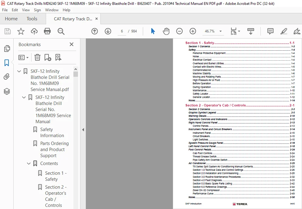
SKF-12 Infinity Blathole Drill Serial No. 1M68M09 Service Manual.pdf......................  0
	SKF-12 Infinity Blathole Drill Serial No. 1M68M09 Service Manual......................  2
		Safety Information................................................................  4
		Parts Ordering and Product Support................................................  5
		Contents..........................................................................  6
			Section 1 - Safety............................................................  6
			Section 2 - Operator's Cab / Controls.........................................  6
			Section 3 - Main Frame / Crawlers.............................................  7
			Section 4 - Engine / Drive Train / Compressor.................................  8
			Section 5 - Dust Control System............................................... 10
			Section 6 - Mast / Rotary Drive / Pipe Rack................................... 11
			Section 7 - Hydraulic Systems................................................. 12
			Section 8 - Electrical Components............................................. 15
			Section 9 - Lubrication and Preventive Maintenance............................ 15
		General Locator................................................................... 17
		Section 1 - Safety ............................................................... 20
			Section 1 Contents............................................................ 22
			Safety........................................................................ 23
		Section 2 - Operator's Cab / Controls............................................. 34
			Section 2 Contents............................................................ 36
			Graphic Symbol Legend......................................................... 38
			Warning Decals................................................................ 43
			Operators Controls and Indicators............................................. 45
			Right Hand Control Panel ..................................................... 46
			Instrument Panel and Circuit Breakers......................................... 47
			System Pressure Gauge Panel .................................................. 49
			Left Hand Control Panel....................................................... 51
			Foot Control Pedals........................................................... 57
			Air Conditioner............................................................... 58
		Section 3 - Main Frame / Crawlers................................................. 84
			Section 3 Contents............................................................ 86
			Main Frame Repair – General................................................... 88
			Levelling Jacks............................................................... 89
			Mast Elevating Cylinders...................................................... 91
			Crawler Assembly.............................................................. 92
			Metric Bolt Torque Specifications............................................. 93
			Track Maintenance............................................................. 94
			Track Tension Adjustment...................................................... 95
			Idler Unit.................................................................... 97
			Track Tension Unit............................................................103
			Track Rollers.................................................................105
			Support Rollers...............................................................110
			Track Chain - Separate........................................................115
			Track Chain - Repair..........................................................116
			Track Shoes Installation......................................................118
			Track Shoe Bolt Torque (Direct Torque Method).................................119
			Track Shoe Bolt Torque (Torque Turn Method)...................................120
			Track Chain and Shoe Installation.............................................121
			Track and Support Rollers.....................................................123
			Final Drive...................................................................129
			Final Drive Unit Removal......................................................130
			Final Drive Unit Installation.................................................131
			Final Drive Maintenance.......................................................132
			Final Drive Oil...............................................................133
			Final Drive Assembly..........................................................135
			Auxiliary Crane...............................................................193
		Section 4 - Engine / Drive Train / Compressor.....................................196
			Section 4 Contents............................................................198
			Power Group Locator ..........................................................201
			Cummins Engine................................................................202
			Engine and Compressor Air Cleaners............................................215
			Compressor Assembly...........................................................219
			ive Train / Compressor........................................................220
			Engine / Drive Train / C......................................................221
			Pump Drive....................................................................222
			Pump Drive Gearbox............................................................223
			Hydraulic Pumps...............................................................225
			Compressor Service Procedures.................................................227
			Compressor Shaft Seal.........................................................231
			High Pressure CompressorCompressor............................................234
			Compressor Oil Circuit........................................................241
			Compressor Condensatio Table..................................................244
			Compressor Air Circuit........................................................245
			Compressor Functional Description.............................................260
			Compressor Operation..........................................................262
			Compressor Maintenance........................................................265
			Compressor Oil Cooler Assenbly................................................298
			Hydraulic Oil / Radiator Cooler Assembly......................................299
			Coolers Maintenance...........................................................300
			Compressor Oil / Hydraulic Oil Cooler Service Manual..........................301
			Radiator Cooler Service Manual................................................306
		Section 5 - Dust Control System...................................................314
			Section 5 Contents............................................................316
			Dust Control System...........................................................318
			Water Injection...............................................................319
			Water Pump....................................................................324
			Foam Injection System.........................................................331
		Section 6 - Mast / Rotary Drive / Pipe Rack ......................................346
			Section 6 Contents............................................................348
			Mast Weldment ................................................................350
			Mast Assembly.................................................................351
			Feed Cylinders................................................................356
			Hoist / Pulldown Cable Assembly...............................................358
			Hoist / Pulldown Cable Adjustment.............................................359
			Rotary Head Guide Alignment...................................................364
			Rotary Drive Assenbly.........................................................365
			Rotary Drive Gearbox..........................................................367
			Winch Assembly................................................................411
			H.O.B.O. Wrench...............................................................447
			Deck Wrench...................................................................449
			Pipe Positioner...............................................................450
			Carousel Pipe Rack............................................................451
		Section 7 Hydraulic Systems.......................................................462
			Section 7 Contents............................................................464
			Hydraulic Symbols.............................................................466
			Hydraulic Tank................................................................468
				Hydraulic Tank............................................................469
				Hydraulic System..........................................................469
			Pressure Setting Sequence.....................................................470
				Pressure Setting Sequence.................................................470
				Hydraulic System..........................................................470
			Main Return and Case Drain Filter.............................................471
				Routine Maintenance.......................................................472
				Changing Filter Elements..................................................472
			Main Hydraulic Pumps..........................................................473
				Hydraulic Pump Identification – SKF-12.....................................473
				Hydraulic Piston Pumps – Removal and Replacement..........................474
			Right Track/Pulldown, Left Track/Rotation Pumps...............................475
				Main Pumps................................................................475
				AA4VG 125 Hydraulic Pump EP2 Control......................................475
				AA4VG EP Controller.......................................................477
				Technical Data............................................................478
				EP (24V DC) Control.......................................................480
				Schematic Drawing – Standard Model........................................480
				Port Locations............................................................483
				Connections...............................................................483
				Main Pump Adjustments.....................................................484
				Change Pressure, High Pressure, P.O.R. and Zero Positions Setting.........485
				Set Charge Pressure – 450psi (31bar)......................................486
				Set Crossover Relief (High Pressure) – 5500psi (380bar)...................486
				Set Pressure Override (P.O.R) – 5000psi (345bar)..........................487
				Mechanical Zero Position..................................................488
				Hydraulic Centreing.......................................................489
				Removal and Inspection of Charge Pump.....................................490
				Removal and Installation of Shaft Seal....................................491
				Routine Maintenance.......................................................492
			Hydraulic Piston Pumps - Maintenance..........................................495
			Hydraulic Piston Pumps - Troubleshooting......................................497
			Charge Circuit................................................................501
				Double Gear Pump – Right Charge and Water Injection.......................501
				Routine Maintenance.......................................................504
				Changing Filter Elements..................................................504
			Loop Filters..................................................................505
				Loop Filters..............................................................505
				Routine Maintenance.......................................................508
				Changing Filter Elements..................................................508
			Diverter Valve................................................................509
				Operation.................................................................509
				Diverter Valve............................................................509
			Tram Circuit..................................................................511
				Tram Circuit..............................................................512
			Hoist/Pulldown Circuit........................................................513
				Basic Pulldown Circuit....................................................513
				Hoist/Pulldown Circuit....................................................514
			Rope Tensioning Circuit.......................................................515
				Auto Tensioning – Operating Principle.....................................515
			Rotation Circuit..............................................................517
				Rotation Circuit..........................................................517
			Rotary Drive Gearbox Motor....................................................519
				Rotation Motor............................................................524
			Fan and Auxiliary Pump Circuit................................................533
				Fan & Auxiliary Functions Pump............................................535
			Hydraulic Pumps...............................................................536
				Hydraulic Piston Pumps - Removal and Replacement..........................536
				Model A11VLO Hydraulic Piston Pumps - Repair..............................536
				Repair Instructions.......................................................537
			New or Rebuilt Hydraulic Pump - Start-Up......................................538
				Start-Up Procedure........................................................538
			Auxiliary Functions/Fan Circuit...............................................540
				Operation.................................................................541
				Auxiliary Priority Function...............................................546
			Cooler Fan Circuit............................................................547
			Cooler Fan Motor..............................................................549
				Hydraulic Motor F12 Series................................................552
			Jack and Mast Elevate Circuit.................................................553
				4 Bank Valve (fig. 7-14)...................................................553
			Counterbalance Valve Adjustment...............................................555
				Counterbalance Valve Adjustments..........................................555
			Mast Elevating Cylinders......................................................556
				Mast Elevating Cylinders Counterbalance Valves............................556
			Levelling Jack Cylinders......................................................557
				Jack Counterbalance Valves................................................557
			Auxiliary Functions/6 Bank Valve..............................................558
			Auxiliary Functions/9 Bank Valve..............................................560
			Hydraulic Operated Breakout Wrench (HOBO).....................................561
				Setting of Sequence Valves................................................561
			Mast Raise / Jacks Valve & Water / Foam Valve.................................562
			Carousel Rotate Motor.........................................................567
			Pilot Control Manifold........................................................574
				Electro Proportional Valves...............................................584
				Proportional Valve Set Up.................................................585
				OEM Electro Proportional Mast Raise / Jacks Valve.........................585
				Proportional Pulldown.....................................................586
				OEM Controllers / EP Levers...............................................587
				Auto Pulldown Card........................................................588
				Reduced Pulldown Potentiometer 'Pot'......................................589
			Hydraulic Gear Pumps..........................................................590
				Hydraulic Gear Pumps - Removal and Replacement............................590
				Hydraulic Gear Pump - Repair..............................................590
				Hydraulic Gear Pumps -  Shaft Seal Removal        and Replacement.........591
			Dust Collector/Water Injection Circuit........................................593
			Air Conditioner Compressor Drive Circuit......................................595
			Hydraulic Cylinder Repair.....................................................597
			Notes.........................................................................612
		Section 8 - Electrical Components.................................................614
			Section 8 Contents............................................................616
			Electrical Locator ...........................................................618
			Jump Starting.................................................................620
			Batteries.....................................................................622
			Welding Precautions...........................................................623
			Vigilante Guide...............................................................624
			Vendor Documents..............................................................616
				Access Light Timer........................................................644
				CF Card Download..........................................................650
				Foam Flow Transducer......................................................651
				C 20 Flow Switch..........................................................659
				Hammer Oil Level Transducer...............................................661
				Hydraulic Flow Meter......................................................665
				Inclinometer..............................................................667
				Ladder Prox Switch (Old Type).............................................682
				Ladder Prox Switch........................................................684
				ld4ivman..................................................................685
				LDM41A Laser Manual.......................................................722
				Calibrating Laser Depth System............................................759
				Level Switch..............................................................760
				Level Transducers.........................................................770
				Remote Level Display......................................................785
				Rod Counter Prox Switch...................................................786
				RotaPulse.................................................................788
				TT0061....................................................................790
				Temperature Transducer....................................................791
				Rexroth RC4 4 20 Electronic Control Unit for Water Flow Control Valve ....809
		Section 9 - Lubrication and Preventive Maintenance................................819
			Section 9 Contents............................................................821
			Central Lube System...........................................................823
			Hammer Oiler Tank Assembly....................................................867
			Hammer Oil Circuit............................................................868
			Hammer Oil System.............................................................869
			Pipe Thread Lubricator Maintenance............................................889
			Filter Locator................................................................900
			Lubrication General...........................................................902
			Lubrication and Preventive Maintenance........................................903
			250hr - Lubrication and Maintenance...........................................918
			500hr - Lubrication and Maintenance Maintenance...............................933
			1000hr - Lubrication and Maintenance..........................................949
			2000hr - Lubrication and Maintenance..........................................965
CAT ROTARY TRACK DRILL MD6240 SKF-12 INFINITY BLASTHOLE DRILL SERVICE MANUAL – PDF DOWNLOAD:
IMAGES PREVIEW OF THE MANUAL:


PLEASE NOTE:
- This is the SAME exact manual used by your dealers to fix your vehicle.
- The same can be yours in the next 2-3 mins as you will be directed to the download page immediately after paying for the manual.
- Any queries / doubts regarding your purchase, please feel free to contact [email protected]
S.M