Cat Rotary Track Drill MD6240 SKF-12 Infinity Blasthole Drill Service Manual – PDF DOWNLOAD
Original price was: $80.00.$37.95Current price is: $37.95.
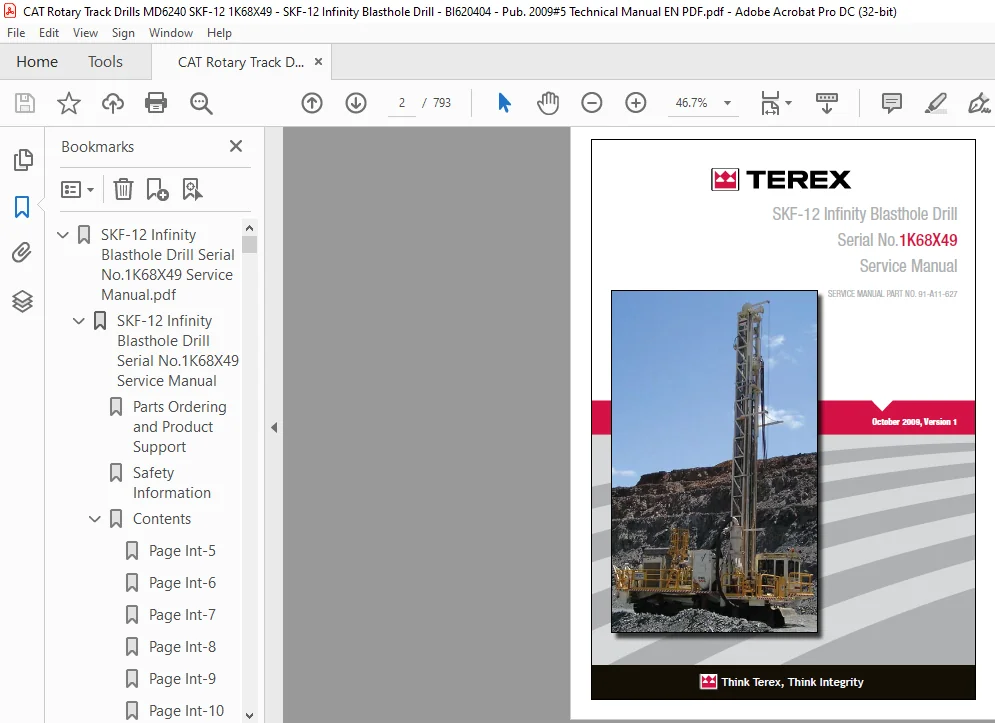
Cat Rotary Track Drill MD6240 SKF-12 Infinity Blasthole Drill Service Manual – PDF DOWNLOAD
Serial No.1K68X49
SERVICE MANUAL PART NO. 91-A11-627
Description
Cat Rotary Track Drill MD6240 SKF-12 Infinity Blasthole Drill Service Manual – PDF DOWNLOAD
DESCRIPTION:
Cat Rotary Track Drill MD6240 SKF-12 Infinity Blasthole Drill Service Manual – PDF DOWNLOAD
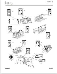
Safety Information
This safety alert symbol indicates important safety messages in this manual. When you see this symbol, carefully read the message that follows and be alert to the possibility of personal injury or property damage
WARNING: BEFORE STARTING ENGINE:
• Study Operator and Service Manuals
• Study Engine Operator and Maintenance Manual
• Practice All Safety Precautions
• Make Pre-Operation Check
• Learn Controls Before Operating
WARNING:
DO NOT use this machine for any other purpose than blasthole drilling. The Infi nity Series rotary blasthole drill is designed for blasthole drilling purposes only. Any other use could result in personal injury and/or property damage and will void the warranty.
CAUTION:
Each person performing service work must be satisfi ed that they have adequate knowledge and training to perform the required tasks. A thorough understanding of hydraulic and pneumatic systems as well as electrical and mechanical knowledge and experience is required.
- This manual is furnished with your Infi nity Series rotary blasthole drill to aid you in performing the necessary service work to maintain your drill in good operating condition.
- This manual contains repair and adjustment information for all major operating systems on the machine. In some cases such as hydraulic pumps and motors it is better to replace the unit with a new or rebuilt unit than to perform major repairs.
- Should further information be desired or should particular problems arise which are not covered suffi ciently in this manual, the matter should be referred to manufacturer.
The descriptions and specifi cations contained in this manual were in effect at the time of printing. The right is reserved to make changes at any time without notice and without obligation.
- The descriptions and specifi cations contained in this manual were in effect at the time of printing. The right is reserved to make changes at any time without notice and without obligation. It is YOUR responsibility to understand and follow manufacturer’s instructions on machine operation and service, and to observe pertinent safety precautions, laws and regulations.
- Failure to read and understand this manual and all safety, capacity and instruction placards on the machine before operating the unit, constitutes a misuse of the machine. It is your responsibility to know the manufacturer’s specifi c requirements, government regulations, required precautions and any work hazards which may exist.
- You must make these known to all personnel working with the equipment or in the area, so that all may take the necessary and required safety precautions. Keep all children, visitors, and untrained personnel away from the equipment.
- It is also your responsibility to operate your equipment with skill, good judgment, and caution. Following recognised safety procedures will help you avoid accidents. Failure to heed these instructions can result in property damage, serious injury or death.
TABLE OF CONTENTS:
Cat Rotary Track Drill MD6240 SKF-12 Infinity Blasthole Drill Service Manual – PDF DOWNLOAD
SKF-12 Infinity Blasthole Drill Serial No.1K68X49 Service Manual.pdf..................................  0
	SKF-12 Infinity Blasthole Drill Serial No.1K68X49 Service Manual..................................  2
		Parts Ordering and Product Support............................................................  4
		Safety Information............................................................................  5
		Contents......................................................................................  6
			Page Int-5................................................................................  6
			Page Int-6................................................................................  7
			Page Int-7................................................................................  8
			Page Int-8................................................................................  9
			Page Int-9................................................................................ 10
			Page Int-10............................................................................... 11
			Page Int-11............................................................................... 12
			Page Int-12............................................................................... 13
			Page Int-13............................................................................... 14
			Page Int-14............................................................................... 15
			Page Int-15............................................................................... 16
			Page Int-16............................................................................... 17
			Page Int-17............................................................................... 18
		General Locator............................................................................... 19
			General Locator........................................................................... 19
		Notes......................................................................................... 21
		Section	1 Safety.............................................................................. 22
			Contents.................................................................................. 24
				Page 1-3.............................................................................. 24
			Safety.................................................................................... 26
				Personal	Protective	Equipment......................................................... 26
				Noise................................................................................. 26
				Electrical	Contact.................................................................... 26
				Overhead	and	Buried	Utilities......................................................... 26
				Contact	with	Electric	Wires........................................................... 27
				Contaminated Air ..................................................................... 27
				Machine	Stability..................................................................... 28
				Moving	and	Rotating	Parts	............................................................ 29
				High	Pressure	Air	or	Fluid............................................................ 29
				Before	Operation...................................................................... 29
				During	Operation...................................................................... 30
				Maintenance........................................................................... 32
				Safety	Locator........................................................................ 33
			Notes..................................................................................... 35
		Section 2 Operator's Cab / Controls........................................................... 36
			Contents.................................................................................. 38
				Page 2-3.............................................................................. 38
			Graphic Symbol Legend..................................................................... 39
			Warning Decals............................................................................ 43
			Operators Controls and Indicators......................................................... 45
				Operator	Control	Panel................................................................ 45
				System	Pressure	Gauge	Panel........................................................... 48
				Switch	Panel.......................................................................... 49
				Switches	/	Diagnostic	Control	Panel................................................... 52
			Cab Heater................................................................................ 53
				Cab	Heater	Fault	Isolation............................................................ 53
			Air Conditioning.......................................................................... 54
				TDR7BX1	Packaged	Unit	Manual.......................................................... 54
				Section	1.0	–	Introduction............................................................ 56
				Section	2.0	–	Unit	Specificatio	and	Settings.......................................... 57
				Section	3.0	–	Technical	Data	and	Control	Settings..................................... 62
				Section	4.0	–	Installation	and	Commissioning.......................................... 64
				Section	5.0	–	Operating	Instructions.................................................. 76
				Section	6.0	–	Routine	Maintenance	Procedures.......................................... 78
				Section	7.0	–	Fault	Diagnosis......................................................... 84
				Section	8.0	–	Warranty................................................................ 95
				Electrical	Schematic.................................................................. 96
			Notes..................................................................................... 98
		Section 3 Main Frame / Crawlers...............................................................100
			Contents..................................................................................102
				Page 3-3..............................................................................102
				Page 3-4..............................................................................103
			Main Frame Repair - General...............................................................104
				Main Frame Repair.....................................................................104
			Weld Inspection Schedule..................................................................105
				Main Frame............................................................................105
			Levelling Jacks...........................................................................106
				Levelling Jacks.......................................................................107
				Levelling Jack Cylinders .............................................................107
				Lubricating Jack Casings..............................................................107
			Mast Elevating Cylinders..................................................................108
				Mast	Elevating	Cylinders..............................................................108
			Crawler Assembly..........................................................................109
				Crawler Assembly......................................................................109
				Crawler Component Repair..............................................................109
			Metric Bolt Torque Specification..........................................................110
			Track Maintenance.........................................................................111
				Before	Operating	the	Machine..........................................................111
				General Maintenance...................................................................111
			Track Tension Adjustment..................................................................112
			Track Chain...............................................................................114
				Separate	Track	Chain	Assembly.........................................................114
				Track	Link	–	Repair	and	Replace.......................................................115
			Track Shoes...............................................................................117
				Track	Link	Position...................................................................117
				Track	Shoe	–	Mounting	to	Track	Chain..................................................117
			Track Shoe Bolt Torque (Direct Torque Method).............................................119
				Bolt Torque KN111.....................................................................119
			Track Shoe Bolt Torque (Torque Turn Method)...............................................120
				Bolt Torque KN111.....................................................................120
			Track Chain and Shoe Installation.........................................................121
				Track Chain with Shoes................................................................121
				Track Chain and Shoe – Assembly and Installation......................................121
			Final Drive ..............................................................................123
				General Description...................................................................123
				Removal	from	Track	Frame..............................................................124
				Installation	into	Track	Frame.........................................................125
				Oil	Check	/	Change....................................................................126
			Final Drive Oil...........................................................................127
				Specifications.........................................................................127
				Recommended Oils......................................................................127
			Final Drive Assembly......................................................................129
				Fianl Drive Assembly..................................................................129
				Parking Brake – Description...........................................................131
				Parking Brake – Removal and Installation..............................................132
				Towing Procedure – Gear Drive Disconnect..............................................132
				Repair Manual Final Drive Model F100..................................................133
				A – General Information...............................................................133
				B – Safety Instructions...............................................................138
				C – General Specifications.............................................................142
				D –  Disassembly and Assembly Operations..............................................151
				E – Troubleshooting...................................................................185
				F – Special Tools.....................................................................186
			Idler Unit................................................................................187
				General Description...................................................................187
				Removal and Disassembly...............................................................189
				Assembly and Installation.............................................................191
			Track Tension Unit........................................................................193
				Installation..........................................................................194
			Track Rollers.............................................................................195
				General Description...................................................................195
				Track Roller Assembly.................................................................196
			Auxiliary Crane...........................................................................197
				Palfinge	Hydraulic	Crane	PC1300	Operators	Manual......................................197
				Possible	Dangers......................................................................198
				During	Operation	of	the	Crane.........................................................199
				Visual Inspections....................................................................201
				Survey	of	the	Crane...................................................................202
				During	Operation	of	the	Crane.........................................................204
				Safety	Devices........................................................................207
				Optional Features.....................................................................210
				Maintenance...........................................................................211
				Cleaning	the	Crane....................................................................217
				PC1300	Specification..................................................................217
				Remote Winch Pendant..................................................................222
			Notes.....................................................................................223
		Section 4 Engine / Drive Train / Compressor...................................................224
			Contents..................................................................................226
				Page 4-3..............................................................................226
				Page 4-4 .............................................................................227
			Engine and Drive Train Service Procedures.................................................228
				Service Procedures Outlined in this Section Include...................................228
				Power Train...........................................................................228
				Engine Service Procedures.............................................................228
				Caterpillar 3412E Engine..............................................................229
				Engine and Compressor Air Cleaner Service.............................................230
			Engine and Compressor Air Cleaners........................................................231
				Engine and Compressor Air Cleaner Service.............................................231
			Flexible Drive Couplingr..................................................................234
				Flexible Drive Coupling Service.......................................................234
			Pump Drive................................................................................236
				Pump Drive Assembly – Removal and Replacement.........................................236
			Pump Drive Gearbox........................................................................237
				Pump Drive Gearbox – Repair...........................................................237
			Hydraulic Pumps...........................................................................239
				Hydraulic Pump Identifi cation.........................................................239
				Hydraulic Pumps – Removal and Replacement.............................................240
			Compressor Service Procedures.............................................................241
				Compressor Drive Coupling.............................................................241
				Compressor Drive Coupling – Removal and Replacement...................................241
				Mounting Instructions for ARCUSAFLEX™ Flywheel Couplings..............................242
				Taper-Loc Bushing Installation – Model AC-T5.SN. F2. V1. 3535.........................243
				Tightening Torques for ARCUSAFLEX™ Flywheel Couplings.................................243
				Before Installation and Start-up of New or Rebuilt Compressor.........................244
				Compressor Unit – Installation........................................................244
			Compressor Shaft Seal.....................................................................245
			High Pressure Compressor..................................................................248
				Safety................................................................................248
				Description...........................................................................251
				Compressed Air Functions..............................................................251
			Compressor Oil Circuit....................................................................255
				Compressor Oil Circuit................................................................255
				Compressor Oil Circuit – 1150cfm @ 350psi.............................................256
			Compressor Condensation Table.............................................................257
			Compressor Functional Description.........................................................258
			Compressor Operation......................................................................261
				Operation.............................................................................261
				Compressor Air Circuit – 1150cfm @ 350psi.............................................264
				Initial Start-up Procedure............................................................265
			Compressor Maintenance....................................................................267
				General Maintenance...................................................................267
				Interstage Tube.......................................................................269
				Discharge Check Valve ................................................................270
				Separator/Receiver Tank...............................................................271
				Scavenge Line.........................................................................273
				Compressor Discharge Temperature Switches, Senders and Gauges.........................274
				Minimum Pressure / Check Valve........................................................275
				Minimum Pressure / Check  Valve Maintenance...........................................275
				Thermal / Bypass Valve................................................................276
				Thermal Bypass Valve Maintenance......................................................277
				Compressor Fluid Filter...............................................................278
				Changing Filter Elements..............................................................278
				Fluid Stop Valve......................................................................280
				Inlet Valve...........................................................................282
				Relieving Regulators..................................................................284
				Reducing Regulators...................................................................286
				Reducing Regulator Maintenance........................................................287
				System Blowdown Valve.................................................................289
				Running Blowdown Valve................................................................290
				Running Blowdown Maintenance..........................................................291
				Moisture Separator Maintenance........................................................292
				Troubleshooting.......................................................................293
			Fan / Oil Cooler Piping...................................................................295
				Fan / Oil Cooler Piping...............................................................295
			Fan and Motor Installation................................................................296
				Fan and Motor Installation............................................................296
			Compressor Oil / Hydraulic Oil Cooler Service Manual......................................297
				Standard Parts – High Pressure Oil Coolers............................................297
				Repair Instructions – External Cleaning and Tube Removal..............................298
				Repair Instructions – Seal Removal, Heater Plate Preparation and Seal Installation....299
				Repair Instructions – Tube Installation, Final Assembly and Testing...................300
				Repair Instructions – Special Header Plate Repair.....................................301
			Radiator / Oil Cooler Repair..............................................................302
				Typical Radiator Core – Standard Parts................................................303
				Cleaning..............................................................................304
				Tube Removal..........................................................................304
				Seal Installation.....................................................................305
				Tube Installation.....................................................................306
			Notes.....................................................................................308
		Section 5 Dust Control System.................................................................310
			Contents..................................................................................312
				Page 5-3..............................................................................312
			Dust Control System.......................................................................314
				Dust Control Systems..................................................................314
			Water Injection...........................................................................315
				Pressure Adjustment...................................................................315
				Water Injection Circuit...............................................................316
				Basic Water Injection System..........................................................317
			Water Pump................................................................................318
				Pump	Specification....................................................................318
				Servicing	Instructions................................................................318
				Water Injection Pump and Parts List...................................................319
				Replacing Piston Cup Seals............................................................320
				Replacing Suction and Discharge Valves................................................321
				Replacing Power End Bearings..........................................................322
				Servicing the Wrist Pin Bearings......................................................323
				Fastener Torque Requirements..........................................................323
				Recommended Lubricants................................................................324
				Water Pump Motor Repair...............................................................324
				Water Injection Hydraulic Control Valve Repair........................................324
				Water Pump Drive Coupling.............................................................324
				Level and Flow Transducer.............................................................324
			Water Pump Motor..........................................................................325
				Char-Lynn®	Hydraulic	Motor	Manual	–	'H'	Series........................................325
				Tools	Required	for	Disassembly	and	Reassembly.........................................326
				Shaft Seal Repair.....................................................................327
			Notes.....................................................................................330
		Section 6 Mast / Rotary Drive / Pipe Rack.....................................................332
			Contents..................................................................................334
				Page 6-3..............................................................................334
				Page 6-4 .............................................................................335
			Mast Weldment.............................................................................336
				Mast Repair...........................................................................336
			Weld Inspection Schedule..................................................................337
				Inspection Mast.......................................................................337
			Mast Assembly.............................................................................338
				Mast Assembly 12m.....................................................................338
				Mast Pivot Caps.......................................................................339
				Mast Elevate Cylinders................................................................339
				Angle Drilling........................................................................340
			Feed Cylinders............................................................................341
				SKF Feed System.......................................................................341
				Removal...............................................................................342
				SKF-12 Feed Cylinder..................................................................343
				Repair................................................................................344
				Installation..........................................................................344
			Hoist / Pulldown Cable....................................................................345
				Auto Tensioning – Operating Principle.................................................346
				Auto Tensioning – Cable Removal, Installation and Adjustment..........................346
				Rope Tensioning Circuit...............................................................348
				Wire Rope.............................................................................350
				Sheave Rollers........................................................................350
			Rotary Head Guide Alignment...............................................................351
				Alignment Procedure:..................................................................351
			Rotary Drive Assembly.....................................................................352
				Rotary Drive Assembly.................................................................352
				Rotary Drive – Removal from Mast......................................................353
				Rotary Drive – Installation...........................................................353
			Rotary Drive Gearbox......................................................................354
				Single Motor Rotary Drive Gearbox.....................................................354
				Air Swivel (Dual Seal Style)..........................................................356
				Service...............................................................................356
				Rotary Drive Motor – Repair...........................................................357
				Top Mast Drive Transmission TM2132-4 Manual...........................................358
				Preface...............................................................................359
				General Working Instructions..........................................................360
				Work Safety...........................................................................361
				Symbol Explanation....................................................................361
				Conversion Table......................................................................362
				Torque Limit Table Grade 5 UNC........................................................363
				Torque Limit Table Grade 5 UNF........................................................364
				Torque Limit Table Grade 8 UNC........................................................365
				Torque Limit Table Grade 8 UNF........................................................366
				Inscription of the Model Identification Plate..........................................367
				Disassembly Transmission..............................................................368
				Assembly Transmission.................................................................375
			Rotary Drive Motor........................................................................393
				Rotary Drive Motor....................................................................393
			Winch Assembly............................................................................394
				Precautions on the Use of Winches.....................................................394
				Wire Rope.............................................................................394
				Wedge Sockets.........................................................................396
				Grooved Drums.........................................................................396
				Drums – Multiple Layers...............................................................397
				Winch Assembly Service................................................................398
				BG8A and BG8B Hydraulic Winch Service Manual..........................................399
				Forward...............................................................................400
				Explanation of Model Number...........................................................400
				Theory of Operation...................................................................401
				Winch Installation....................................................................403
				Wire Rope Installation................................................................404
				Preventative Maintenance..............................................................405
				071 Motor.............................................................................406
				Troubleshooting.......................................................................407
				Disassembly of Winch..................................................................411
				Planetary Carrier Service.............................................................413
				Motor Support Brake Cylinder Service..................................................415
				Brake Clutch Service..................................................................419
				Winch Assembly........................................................................421
				Brake Valve Service...................................................................423
				Reversing Direction of Drum Rotation..................................................425
				Recommended Fastener Torque...........................................................426
				Metric Conversion Table...............................................................427
			H.O.B.O. Wrench...........................................................................428
				Tong Dies.............................................................................429
			Deack Wrench..............................................................................430
			Pipe Positioner...........................................................................431
				Pipe Positioner.......................................................................431
			Carousel Pipe Rack........................................................................432
				If Pipe Rack Does Not Rotate..........................................................432
				Chain Drive – Adjust/Replace..........................................................432
				Pipe Rack Bearings – Replace..........................................................433
				Carousel Top Tube Bearing – Replace...................................................434
				Carousel Lower Bearing – Replace......................................................436
				Carousel Pivot Support Upper Bearing – Replace........................................438
				Carousel Pivot Support Lower Bearing - Replace........................................440
				Mid-Point Carousel Pivot Support......................................................441
				Carousel Rotate Motor.................................................................441
			Notes.....................................................................................442
		Section 7 Hydraulic Systems...................................................................444
			Hydraulic Symbols.........................................................................450
			Hydraulic Tank............................................................................452
				Hydraulic Tank........................................................................453
				Hydraulic System......................................................................453
			Pressure Setting Sequence.................................................................454
				Pressure Setting Sequence.............................................................454
				Hydraulic System......................................................................454
			Main Return and Case Drain Filter.........................................................455
				Routine Maintenance...................................................................456
				Changing Filter Elements..............................................................456
			Main Hydraulic Pumps......................................................................457
				Hydraulic Pump Identification..........................................................457
			Right Track/Pulldown, Left Track/Rotation Pumps...........................................458
				Hydraulic Piston Pumps – Removal and Replacement......................................458
				Main Pumps............................................................................459
				AA4VG 125 Hydraulic Pump EP2 Control..................................................459
				AA4VG EP Controller...................................................................461
				Technical Data........................................................................462
				EP (24V DC) Control...................................................................464
				Schematic Drawing – Standard Model....................................................464
				Port Locations........................................................................467
				Main Pump Adjustments.................................................................468
				Set Charge Pressure – 450psi (31bar)..................................................470
				Set Crossover Relief (High Pressure) – 5500psi (380bar)...............................470
				Set Pressure Override (P.O.R) – 5000psi (345bar)......................................471
				Mechanical Zero Position..............................................................472
			Hydraulic Piston Pumps - Maintenance......................................................473
				Hydraulic Centreing...................................................................473
				Removal and Inspection of Charge Pump.................................................474
			Hydraulic Piston Pumps - Troubleshooting..................................................475
				Removal and Installation of Shaft Seal................................................475
				Routine Maintenance...................................................................476
			Charge Circuit............................................................................481
				Double Gear Pump – Right Charge and Water Injection...................................481
				Charge	Circuit	Schematic..............................................................482
				Routine Maintenance...................................................................484
				Changing Filter Elements..............................................................484
			Loop Filters..............................................................................485
				Loop Filters..........................................................................485
				Routine Maintenance...................................................................488
				Changing Filter Elements..............................................................488
			Diverter Valve............................................................................489
				Diverter	Valve........................................................................489
				Operation.............................................................................489
				Diverter	Valve........................................................................489
			Hydraulic Feed and Rotation Circuits......................................................490
				Basic Left Track / Rotation Pump Circuit..............................................490
				Basic Left Track / Rotation Pump......................................................490
				Rotation Circuit......................................................................491
				Basic	Right	Track	/	Pulldown	and	Hoist	Circuit........................................492
				Basic	Right	Track	/	Pulldown	and	Hoist................................................492
				Hoist / Pulldown Circuit..............................................................493
			Drill / Tram Control Circuit..............................................................494
				Operation.............................................................................494
			Rope Tensioning Circuit...................................................................497
				Auto Tensioning – Operating Principle.................................................497
			Rotary Drive Gearbox Motor................................................................498
				Variable Displacement Motor AA6VM.....................................................498
				Rotation Motor........................................................................502
			Fan and Auxiliary Pump Circuit............................................................512
				Hydraulic	Pump	Identif	cation	........................................................512
				Fan and Auxiliary Functions Pump......................................................514
			Hydraulic Pumps...........................................................................515
				Hydraulic Piston Pumps – Removal and Replacement......................................515
				Model A11VLO Hydraulic Piston Pumps – Repair..........................................515
				Repair Instructions...................................................................516
			New or Rebuilt Hydraulic Pump - Start-up..................................................517
				Start-Up Procedure....................................................................517
			Auxiliary Functions/Fan Circuit...........................................................519
				Operation.............................................................................520
				Auxiliary Fan.........................................................................524
				Auxiliary Priority Function...........................................................525
			Cooler Fan Circuit........................................................................526
				Cooler Fan Circuit....................................................................526
			Cooler Fan Motor..........................................................................528
				F12 Service Manual....................................................................528
				Specification and Tools...............................................................529
				Hydraulic Motor F12 Series............................................................531
			Jack and Mast Elevate Circuit.............................................................532
				4	Bank	Valve..........................................................................532
			Counterbalance Valve Adjustment...........................................................534
				Counterbalance Valve Adjustments......................................................534
			Mast Elevating Cylinders..................................................................535
				Mast Elevating Cylinders Counterbalance Valves........................................535
			Levelling Jack Cylinders..................................................................536
				Jack Counterbalance Valves............................................................536
			Auxiliary Functions/6 Bank Valve..........................................................537
			Auxiliary Functions/9 Bank Valve..........................................................538
			Hydraulic Operated Breakout Wrench (H.O.B.O) .............................................539
				Setting of Sequence Valves............................................................539
			Carousel Rotate Motor.....................................................................540
				Disassembly...........................................................................542
				Reassembly............................................................................544
			Pilot Control Manifold....................................................................547
			Hydraulic Gear Pumps......................................................................561
				Hydraulic Gear Pumps – Removal and Replacement........................................561
				Hydraulic Gear Pump – Repair..........................................................561
				Hydraulic Gear Pumps – Shaft Seal Removal and Replacement.............................562
				Tool List.............................................................................563
			Dust Collector / Water Injection Circuit..................................................564
				Pressure Adjustment...................................................................564
				Dust Collector / Water Injection Circuit..............................................565
			Hydraulic Cylinder Repair.................................................................566
				General Information...................................................................567
				H Head................................................................................569
				N Head................................................................................570
				Z Head................................................................................571
				Z Head (Two Piece)....................................................................572
				K Head................................................................................573
				M Head................................................................................574
				Z Piston..............................................................................575
				H and K Piston........................................................................576
				M Piston..............................................................................577
				N Piston..............................................................................580
			Notes.....................................................................................581
			Contents..................................................................................446
				Page 7-3..............................................................................446
				Page 7-4..............................................................................447
				Page 7-5..............................................................................448
		Section 8 Electrical Components...............................................................582
			Contents..................................................................................584
				Page 8-3..............................................................................584
				Page 8-4..............................................................................585
			Electrical Locator........................................................................586
				Electrical Locator....................................................................586
				Machine Isolation.....................................................................587
			Jump	 Starting............................................................................588
				Jump Starting.........................................................................588
			Batteries.................................................................................590
				Batteries.............................................................................590
			Electrical Components.....................................................................591
				Electrical Circuits...................................................................591
				Transducers...........................................................................591
				Joystick Adjustments..................................................................593
			Welding	Precautions.......................................................................595
			Vigilante	Guide...........................................................................596
				Important Information.................................................................596
				PLC...................................................................................597
				Touchscreen...........................................................................600
				Laser depth System....................................................................601
				Start-up and Shutdown.................................................................603
				Alarms................................................................................604
				Solenoid Control......................................................................605
				Auto Lube.............................................................................607
				Hammer oil System.....................................................................607
				Gauges................................................................................608
				Dust Suppression......................................................................608
				Important Information.................................................................609
				Disclaimers...........................................................................609
			Vigilante	System	Component	Information....................................................610
				Ladder Prox Switch....................................................................610
				Jacks Prox Switch.....................................................................610
				LDM 40 A Laser........................................................................611
				General...............................................................................611
				Safety Instructions...................................................................612
				Performance Data......................................................................613
				Working Principle.....................................................................614
				Setup.................................................................................614
				Interface Cable Wire Assignments......................................................615
				Limiting Values for Voltages..........................................................616
				Starting Up...........................................................................616
				Parameters............................................................................617
				Functions.............................................................................620
				Radiator Level Switch.................................................................623
				Hammer oil Level Transducer...........................................................627
				Pressure Transducers – Combined Pressure Sensor.......................................629
				Access Light Timer....................................................................638
				Rod Counter Prox Switch...............................................................639
				Cat 3412E Flash Codes.................................................................640
				Cat 3412E Electrical System...........................................................642
				Cat 3412E Sensor Layout...............................................................643
				Cat 3412E Sensor Schematic............................................................647
			Notes.....................................................................................648
		Section 9 Lubrication and Preventive Maintenance..............................................650
			Contents..................................................................................652
				Page 9-3..............................................................................652
				Page 9-4..............................................................................653
			Central Lube System.......................................................................654
				Description...........................................................................654
				Auto Lube.............................................................................654
				Auto	Lube	Lincoln	Pneumatic	Pump	Owners	Manual........................................655
				SL-1 Injectors........................................................................664
				SL-1 Injector Assembly................................................................664
				SL-1 Injector Specifications...........................................................664
				SL-1 Injector Operation...............................................................665
				Filter	/	Regulator	/	Lubricator.......................................................666
				Filter Maintenance and Repair.........................................................667
				Lubricator Maintenance and Repair.....................................................669
			Air Service Units.........................................................................670
				Filter Regulator......................................................................670
				Air Line Oiler........................................................................671
			Pipe Thread Lubricator....................................................................672
				Air Service Unit......................................................................672
				Air Operated Pipe Thread Pump.........................................................673
			Hammer Oil System.........................................................................681
				Hammer Oiler Tank Assembly............................................................681
				Hammer Oil Circuit....................................................................682
				Air Service Unit Components...........................................................683
				Filter Regulator......................................................................684
				Air Line Oiler........................................................................685
				10:1 Hammer Oil Pump..................................................................686
				Symbols...............................................................................687
				Installation..........................................................................689
				Operation.............................................................................692
				Air Motor and Throat Service..........................................................694
				Dimensions............................................................................699
				Technical Data........................................................................699
				Performance Chart.....................................................................700
			Hammer Oiler Tank Assembly................................................................698
				Displacement	Pump	Service.............................................................698
			Lubrication General.......................................................................701
				Equipment Lubrication.................................................................701
				Care of Lubrication Points............................................................701
			Lubrication and Preventive Maintenance....................................................702
				Isolation – Battery Switch............................................................703
				Track – Checks and Lubrication........................................................704
				Engine	Maintenance....................................................................705
				Air Cleaners..........................................................................706
				Air Filter Elements...................................................................706
				Alternator Maintenance................................................................706
				Compressor – Checks and Servicing.....................................................707
				Air Conditioner – Checks and Servicing................................................708
				Drive Shaft – Checks and Maintenance..................................................708
				Cooler – Checks and Servicing.........................................................709
				Hydraulic – Checks and Servicing......................................................710
				A-frame and Mast Pivot Point – Checks and Maintenance.................................711
				Rotary Head – Checks and Service Points...............................................712
				Pulldown/Hoist Sheaves and Ropes – Checks and Servicing...............................713
				Cabin – Checks and Service Points.....................................................714
				Fire Suppression (Optional) –  Checks and Services....................................714
				Battery – Checks and Servicing........................................................715
				Bean Pump – Checks and Maintenance....................................................715
				Lubrication System – Checks and Servicing.............................................716
			Weld Inspection Schedule..................................................................717
				Weld	Inspection	Schedule	SK	Series....................................................717
			250hr - Lubrication and Maintenance.......................................................718
			500hr - Lubrication and Maintenance.......................................................733
			1000hr - Lubrication and Maintenance......................................................749
			2000hr - Lubrication and Maintenance......................................................765
			Lubricant Specifications..................................................................783
				Equipment	Lubrication.................................................................783
				Care	of	Lubrication	Points............................................................783
				Compressor	Lubrication	Procedure......................................................783
				Winch	Assembly	Lubrication	(Braden	BG-8H).............................................783
				Compressor............................................................................784
				Lubricating	Grease....................................................................784
				Gear Lubricant........................................................................784
				Hydraulic System......................................................................785
				Hydraulic Tank Capacity...............................................................785
				Hydraulic	System	Maintenance..........................................................786
				Cooling	System	Maintenance............................................................786
				Cooling	System	Freeze	Protection......................................................787
				Air	Cleaners..........................................................................787
				Air	Filter	Element....................................................................787
				Electrical	System.....................................................................787
				Scheduled	Oil	Sampling	Analysis.......................................................788
			Torque Values for Split Flange Connections................................................789
				 Procedure No. 1-87 Revision A........................................................789
				Torque Values for Split Flange Connections............................................790
			Notes.....................................................................................792
CAT ROTARY TRACK DRILL MD6240 SKF-12 INFINITY BLASTHOLE DRILL SERVICE MANUAL – PDF DOWNLOAD:
IMAGES PREVIEW OF THE MANUAL:


PLEASE NOTE:
- This is the SAME manual used by the dealers to troubleshoot any faults in your vehicle. This can be yours in 2 minutes after the payment is made.
- Contact us at [email protected] should you have any queries before your purchase or that you need any other service / repair / parts operators manual.
S.M