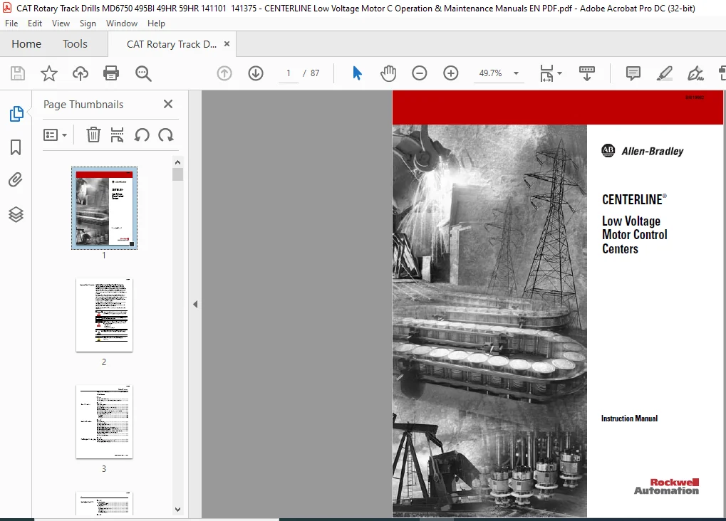
CAT Rotary Track Drills CENTERLINE Low Voltage Motor Control Centers Instruction Manual – PDF DOWNLOAD
Original price was: $80.00.$24.95Current price is: $24.95.
CAT Rotary Track Drills MD6750 495BI 49HR 59HR 141101 141375 – CENTERLINE Low Voltage Motor C Operation & Maintenance Manuals EN PDF
Description
CAT Rotary Track Drills CENTERLINE Low Voltage Motor Control Centers Instruction Manual – PDF DOWNLOAD
DESCRIPTION:
CAT Rotary Track Drills CENTERLINE Low Voltage Motor Control Centers Instruction Manual – PDF DOWNLOAD
Important User Information
- Solid state equipment has operational characteristics differing from those of electromechanical equipment. Safety Guidelines for the Application, Installation and Maintenance of Solid State Controls describes some important differences between solid state equipment and hard-wired electromechanical devices.
- Because of this difference, and also because of the wide variety of uses for solid state equipment, all persons responsible for applying this equipment must satisfy themselves that each intended application of this equipment is acceptable. In no event will Rockwell Automation, Inc.
- be responsible or liable for indirect or consequential damages resulting from the use or application of this equipment. The examples and diagrams in this manual are included solely for illustrative purposes.
- Because of the many variables and requirements associated with any particular installation, Rockwell Automation, Inc. cannot assume responsibility or liability for actual use based on the examples and diagrams.
- No patent liability is assumed by Rockwell Automation, Inc. with respect to use of information, circuits, equipment, or software described in this manual. Reproduction of the contents of this manual, in whole or in part, without written permission of Rockwell Automation, Inc. is prohibited. Throughout this manual, when necessary we use notes to make you aware of safety considerations.
WARNING: Identifies information about practices or circumstances that can cause an explosion in a hazardous environment, which may lead to personal injury or death, property damage, or economic loss.
IMPORTANT: Identifies information that is critical for successful application and understanding of the product.
ATTENTION: Identifies information about practices or circumstances that can lead to personal injury or death, property damage, or economic loss. Attentions help you: • identify a hazard • avoid a hazard • recognize the consequence
SHOCK HAZARD: Labels may be located on or inside the equipment (e.g. drive or motor) to alert people that dangerous voltage may be present.
BURN HAZARD :Labels may be located on or inside the equipment (e.g. drive or motor) to alert people that surfaces may be dangerous temperatures.
TABLE OF CONTENTS:
CAT Rotary Track Drills CENTERLINE Low Voltage Motor Control Centers Instruction Manual – PDF DOWNLOAD
Important User Information Inside Front Cover
Table of Contents
Preface
Recommended Publications v
Purchased Components and Additional Instruction Sheets v
Chapter 1
General Information General Description 1-1
Nameplate Data 1-2
Motor Control Center Sequence Numbering 1-3
UL/CSA Marking 1-4
Short Circuit Rating Label 1-4
Series Number and Series ID as Manufactured in the U S 1-6
Series Lettering – Units & Sections 1-9
Receiving, Handling and Storage 1-10
Receiving 1-10
Handling 1-11
Storage 1-12
Chapter 2
Installation Procedures Location Planning 2-1
Height Considerations 2-1
Securing a Motor Control Center 2-2
Seismic Requirements 2-6
Joining & Splicing New Motor Control Centers 2-7
Joining & Splicing Existing Motor Control Centers 2-8
Installing and Joining Pull Boxes 2-8
Joining and Splicing NEMA Type 12 Motor Control Centers 2-8
Joining & Splicing NEMA Type 3R and Type 4
Motor Control Centers 2-8
Bus Torque Specifications 2-9
Chapter 3
Final Checklist Before Energizing Introduction 3-1
Perform a Pre-Energizing Check Procedure 3-1
Pre-Energizing Check Procedure 3-2
BI619662
Publication 2100-IN012B-EN-P – April 2005
Chapter 4
Installing Conduit and Cable Installing Conduit 4-1
Bottom Entry Conduit 4-1
Top Entry Conduit 4-1
Installing Cable 4-2
Lugs 4-2
Incoming Line Compartment 4-2
Main Disconnect 4-3
Cable Bracing 4-3
Incoming Line Brace 4-5
Chapter 5
Installing and Removing Plug-In
Units
Installing Plug-In Units 5-1
Removing Plug-In Unit with a Vertical Operating Handle
from a Section 5-1
Removing Plug-In Unit with a Horizontal Operating Handle
from a Section 5-4
Removing Support Pan 5-6
Chapter 6
Arc Flash Protection Marking as
Required by the National
Electrical Code
Flash Protection Marking Requirement 6-1
110 16 Flash Protection 6-1
Arc Flash Marking Clarification 6-2
Rockwell Automation Assistance 6-2
Chapter 7
Operator Handle and Unit
Interlock
Defeating the Unit Door Interlock 7-1
Opening the Door when the Operating Handle is in the
ON/I Position 7-1
Defeating the Unit Interlock Lever 7-3
Energizing a Unit with the Unit Door Open 7-3
Locking Provisions 7-4
Locking Vertical Operating Handles in the
OFF/O Position 7-4
Locking Horizontal Operating Handles in the
OFF/O Position 7-5
Locking units with Operating Handles in the
ON/I Position 7-5
Unit Interlocks 7-7
Chapter 8
Energizing Equipment Energizing Procedure 8-1
BI619662
Publication 2100-IN012B-EN-P – April 2005
Chapter 9
Maintenance Maintenance Checklist 9-1
Disconnect Switch and Contact Lubrication 9-4
Instructions 9-4
Chapter 10
Maintenance After Fault Condition Maintenace After Fault Condition 10-1
Chapter 11
Renewal Parts Order Information 11-1
Chapter 12
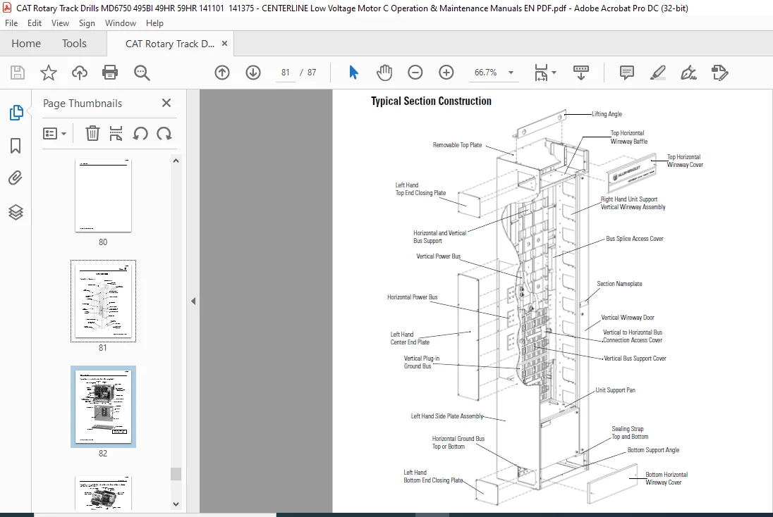
Parts Illustrations Typical Section Construction 12-1
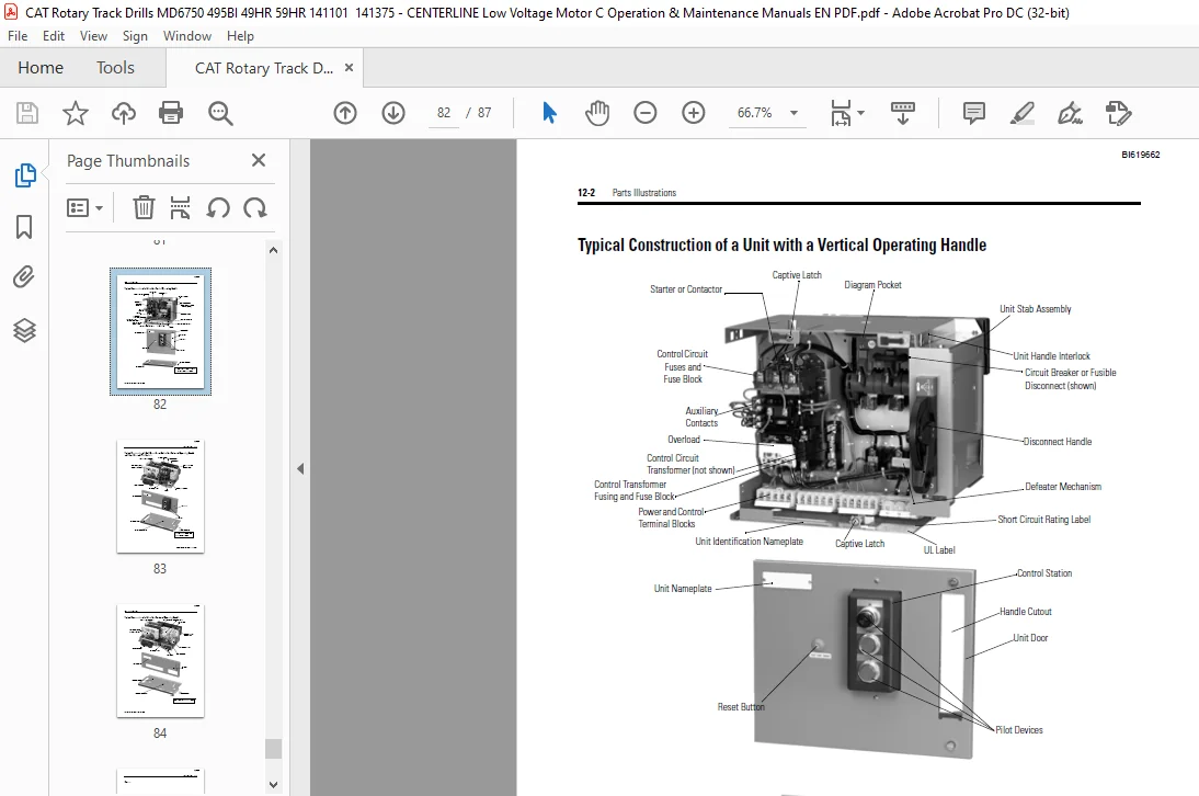
Typical Construction of a Unit with a Vertical
Operating Handle 12-2
Typical Construction of a Half Space Factor Unit with a Horizontal
Operating Handle and Door Mounted Pilot Devices 12-3
Typical Construction of a Unit with a Horizontal
Operating Handle 12-4
Rockwell Automation Support Inside Back Cover
Installation Assistance Inside Back Cover
New Product Satisfaction Return Inside Back Cover
CAT ROTARY TRACK DRILLS CENTERLINE LOW VOLTAGE MOTOR CONTROL CENTERS INSTRUCTION MANUAL – PDF DOWNLOAD:
IMAGES PREVIEW OF THE MANUAL:


PLEASE NOTE:
- This is the SAME exact manual used by your dealers to fix your vehicle.
- The same can be yours in the next 2-3 mins as you will be directed to the download page immediately after paying for the manual.
- Any queries / doubts regarding your purchase, please feel free to contact [email protected]
S.M