CAT Rotary Track Drills QXR 920 Surface Drill System Maintenance Manual – PDF DOWNLOAD
Original price was: $70.00.$26.95Current price is: $26.95.
CAT Rotary Track Drills QXR920 – QXR920 Surface Drill – BI620144 – 1 Operation & Maintenance Manuals EN PDF
Description
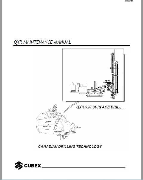
CAT Rotary Track Drills QXR 920 Surface Drill System Maintenance Manual – PDF DOWNLOAD
DESCRIPTION:
CAT Rotary Track Drills QXR 920 Surface Drill System Maintenance Manual – PDF DOWNLOAD
General Safety Instructions
1. Observe all safety procedures when operating and servicing the equipment.
2. Be completely familiar with operating and maintenance procedures before inspecting, operating, or servicing the drill or booster. You must read and understand all procedures described in each manual.
3. Do not inspect or repair any components without properly shutting down drill, water pump, and air supply.
4. Keep all non-essential personnel away from operator’s controls and maintenance area while service work is in progress.
5. Any modifications to controls or operating procedures must be noted clearly on equipment and all operators must be advised of changes.
6. Inspect hoses, hose connection safety devices, fittings, and supply lines at frequent intervals for indication of wear or damage. Repair or replace damaged components immediately. 7. Check all bolts, nuts, and adjustments frequently for proper tension. Check all fluids at recommended intervals.
8. Do not stand under mast at any time.
9. Disconnect electrical power supply to drill and booster before washing. 10. Wear protective gear when operating, diagnosing, or servicing the equipment.
11. Do not weld or grind near electrical wiring or supply lines.
12. Keep hands, clothing, rags, and tools away from moving parts.
13. Keep shields and guards in place. Do not operate equipment with electrical panel door open.
14. Keep safety and instruction decals clean. Replace then if they are not clearly legible. BI620144
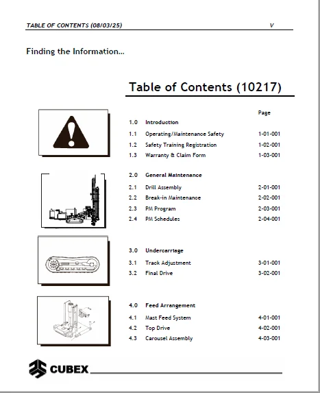
TABLE OF CONTENTS:
CAT Rotary Track Drills QXR 920 Surface Drill System Maintenance Manual – PDF DOWNLOAD
Planning your PM program….....................................................  4
Finding the Information…......................................................  5
        1.1 Operating/Maintenance Safety......................................  9
	    Drill Operation and Maintenance Safety................................ 11
	  General Safety Instructions............................................. 11
	  Safety Instructions for Driving and Operating........................... 12
	  Safety Instructions for Servicing....................................... 12
	Extinguishing Fires....................................................... 18
2.1 Drill Assembly............................................................ 22
2.2 Break-in Maintenance...................................................... 23
2.3 Preventative Maintenance Program.......................................... 24
	2.3.1 Lubrication......................................................... 26
	2.3.2 Lubrication Cross-over.............................................. 27
	2.3.3 Rock Drill Grease................................................... 28
	2.3.4 Lubrication Points and Intervals.................................... 28
	2.3.5 Centralized Machine Lubrication..................................... 29
		Greaser Assembly...................................................... 31
	2.3.6 Drill Filtration Points and Intervals............................... 33
	2.3.7 Bolt Torque......................................................... 34
	2.3.8 Pipe Thread Grease Pump............................................. 35
		2.3.8.1 Preventative Maintenance Tasks................................ 35
		2.3.8.2 Safety........................................................ 36
		2.3.8.3 Maintenance................................................... 37
	2.3.9 Annual Maintenance of the Coolant Heater............................ 38
2.4 Recommended Tools:........................................................ 43
3.1 Track Adjustment.......................................................... 49
3.2 Final Drive............................................................... 50
4.1 Mast Feed System..........................................................264
	4.1.1 QXR Feed Chain Adjustment...........................................266
	4.1.2 Slider Adjustment...................................................269
	4.1.3 Carrier Block.......................................................270
	4.1.4 Feed Chain Block....................................................271
	4.1.5 Jib Boom............................................................272
	4.1.6 Lower Mast..........................................................273
		4.1.6.1 Overhaul procedure............................................274
4.2 Top Drive.................................................................275
	4.2.1 Checking Bearing Pre-load...........................................276
	4.2.2 Adjusting Bearing Pre-load..........................................277
	4.2.3 Removing Top Drive..................................................277
		4.2.3.1 Using the Right Equipment.....................................278
	4.2.4 Disassembly Procedure...............................................279
	4.2.5 Installation of Pinion Gears and Bearings...........................280
	4.2.6 Driveshaft Assembly and Installation................................281
	4.2.7 Setting Bearing Preload.............................................287
	4.2.8 Installing Upper Seal and Housing...................................289
	4.2.9 Installing Air Swivel and Hydraulic Motors..........................291
	4.2.10 Saver Sub..........................................................293
		4.2.10.1 Removal......................................................293
		4.2.10.2 Installation.................................................295
	4.2.11 Air Swivel.........................................................296
		4.2.11.1 Removing Air Swivel..........................................296
		4.2.11.2 Installation of Air Swivel...................................297
		4.2.11.3 Dismantling Air Swivel.......................................299
		4.2.11.4 Inspection of Parts..........................................301
		4.2.11.5 Assembly Procedure...........................................302
4.3 Carousel Assembly.........................................................310
	4.3.1 Carousel Adjustment.................................................313
		4.3.1.1 Pipe Clamp Adjustment.........................................313
		4.3.1.2 Clamp Arm Adjustment..........................................314
5.1 Hydraulic Symbols.........................................................317
5.2 Hydraulic Circuits........................................................318
5.3 Hydraulic Pump............................................................321
	5.3.1 Installation........................................................322
		5.3.1.1 Pre Start-up..................................................322
		5.3.1.2 Start-up......................................................322
	5.3.2 Adjustments.........................................................324
		5.3.2.1 System (Operating) Pressure Adjustment........................324
		5.3.2.2 Stand-by Pressure Adjustment..................................324
	5.3.3 Testing the Pump....................................................325
	5.3.4 Troubleshooting the Pump............................................327
	5.3.5 Factors Affecting the Pump’s Life...................................328
		5.3.5.1 Contaminated Fluid............................................328
		5.3.5.2 Poor Suction Conditions.......................................329
		5.3.5.3 Excessive Case Pressure.......................................330
		5.3.5.4 Too Low an Operating Pressure.................................330
		5.3.5.5 Cavitation/Aeration...........................................331
5.4 Hydraulic Cylinders.......................................................332
	5.4.1 Double Acting Cylinders.............................................333
	5.4.2 Cylinder Inspection.................................................333
	5.4.3 Cylinder Overhaul...................................................333
5.5 Control Valves – On/Off Types.............................................334
	5.5.1 Control Valves......................................................336
	5.5.2 Relief Valve Adjustment.............................................337
	5.5.3 Valve Pressure Adjustment...........................................338
	5.5.4 Valve Flow Adjustment...............................................338
	5.5.5 Valve Overhaul......................................................338
	5.5.6 Valve Sections......................................................340
	5.5.7 Solenoid............................................................340
	5.5.8 Lever Section.......................................................340
	5.5.9 Valve Assembly......................................................342
	5.5.10 Inlet Section......................................................342
5.6 Motorized Pulldown and Holdback Control Adjustment........................344
	5.6.1 Adjusting Pulldown – Maximum Pressure...............................344
	5.6.2 Adjusting Holdback – Maximum Pressure...............................344
5.7 Counterbalance Valves.....................................................345
	5.7.1 Making Adjustments..................................................346
	5.7.2 Troubleshooting.....................................................347
5.8 Hydraulic Filtration......................................................348
	5.8.1 Change Hydraulic Fluid Every 2000 Hours.............................349
	5.8.2 Return Filters......................................................349
	5.8.3 Pressure Filter Element.............................................350
5.9 Proportional Valves.......................................................351
	5.9.1 Proportional Valve Settings.........................................351
	5.9.2 Flow Settings.......................................................352
	5.9.3 Pressure Setting....................................................353
6.1 Air Schematic.............................................................356
6.2 Sullair Compressor........................................................358
	6.2.1 Compressor Unit Functional Description .............................359
	6.2.2 Compressor Discharge System Functional Description..................361
	6.2.3 Compressor Cooling and Lubrication System Functional Description....363
	6.2.4 Air Inlet System Functional Description.............................365
	6.2.5 Lubrication Guide...................................................366
	6.2.6 Application Guide...................................................366
	6.2.7 Control System......................................................367
		6.2.7.1 Purpose of Controls...........................................367
		6.2.7.2 Butterfly Inlet Valve Functional Description..................371
		6.2.7.3 Closed Inlet Start Program....................................372
		6.2.7.4 Normal Operation..............................................373
		6.2.7.5 Modulation....................................................373
		6.2.7.6 Unload........................................................373
		6.2.7.7 Compressor Start Up Mode and Running Mode Low Air Pressure....374
		6.2.7.8 Manual Unload Mode............................................375
		6.2.7.9 Running Mode 350 psi Air Pressure.............................376
		6.2.7.10 Running Mode 500 psi Air Pressure............................377
		6.2.7.11 Instrumentation and Protection...............................378
		6.2.7.12 Start Up and Shutdown Procedures.............................380
		6.2.7.13 Adjustment Procedures........................................382
	6.2.8 Compressor Maintenance..............................................383
		6.2.8.1 Main Fluid Filter Service.....................................383
		6.2.8.2 Thermal/Bypass Valve..........................................384
		6.2.8.3 Separator Element Replacement.................................385
		6.2.8.4 Running Blowdown Valve Maintenance............................387
		6.2.8.5 Shutdown Blowdown Valve Maintenance...........................388
		6.2.8.6 Minimum Pressure/Check Valve Maintenance......................389
		6.2.8.7 Discharge Check Valve Maintenance.............................390
		6.2.8.8 Safety Valve..................................................391
		6.2.8.9 Pressure Regulator (Low / High Air Pressure Regulator)........392
		6.2.8.10 Fluid Stop Valve.............................................394
	6.2.9 Screw Compressor....................................................395
		6.2.9.1 Screw Compressor Arrangement..................................395
	Compressor Operator Daily Checklist.......................................396
		6.2.9.3 Maintenance Schedules.........................................397
		6.2.9.4 Compressor Lubrication Crossover..............................398
		6.2.9.5 Compressor Troubleshooting....................................399
6.3 Water Pump................................................................401
	6.3.1 Pump Speed Adjustment...............................................402
	6.3.2 Dismantling of Valves...............................................403
	6.3.3 Assembling of Valves................................................403
	6.3.4 Dismantling the Pumping Section.....................................404
	6.3.5 Pump Assembly.......................................................404
	6.3.6 Removing Sleeves and Seals..........................................405
	6.3.7 Installing Sleeves and Seals........................................405
	6.3.8 Servicing the Crankcase.............................................406
	6.3.9 Pump Installation...................................................406
6.4 Grease Injection..........................................................407
	6.4.1 To Fill Reservoir...................................................409
	6.4.2 To Prime System.....................................................409
	6.4.3 Operation...........................................................409
	6.4.4 Adjusting Flow Rate.................................................410
		6.4.4.1 Setting for a 4” Hammer.......................................410
		6.4.4.2 Setting for a 6” Hammer.......................................410
	6.4.5 PanelView Settings for QXR..........................................412
7.1 Electrical Circuits.......................................................414
7.2 Electrical Components.....................................................415
7.3 On/Off Valve Activation...................................................416
7.4 Types of Valves...........................................................417
7.5 Testing of Valve Solenoids................................................417
7.6 Testing On/Off Valves.....................................................418
7.7 Proportional Valves.......................................................419
7.8 Fault Monitoring System...................................................420
	7.8.1 Testing Proportional Valves.........................................420
7.9 Accra-Feed PLC System.....................................................422
	7.9.1 Accra-Feed Operation................................................422
	7.9.2 Accra-Feed Components...............................................422
	7.9.3 PLC Operation.......................................................423
	7.9.4 Maintenance of PLC in Accra-Feed System.............................423
	7.9.5 Troubleshooting Guide...............................................424
7.10 Operator Interface PanelView 1000........................................427
	7.10.1 Maintenance of PanelView Terminal..................................427
	7.10.2 Troubleshooting PanelView Terminal.................................428
	7.10.3 Alarm Messages on the Terminal.....................................430
8.0 Troubleshooting...........................................................432
8.1 Troubleshooting Mechanical Systems........................................433
	Tramming does not move or move straight...................................433
	Tramming is too slow or lacks power.......................................433
	Brakes are slipping.......................................................433
	Excessive noise or vibration when tramming................................434
	Mast swing does not rotate................................................434
	Mast rotates erratically or rotates after setting.........................434
	Mast rocks back and forth.................................................434
	Hydraulic cylinders not operating.........................................434
	Cylinder creep............................................................435
	Centralizer does not retract..............................................435
	Oil leakage at stinger cylinder...........................................435
	Pulldown control does not function correctly..............................435
	Holdback control does not function correctly..............................435
	Top drive does not rotate, or rotation is slow or rough...................435
	Splined piston in top drive does not retract..............................436
	Rotation and Feed joysticks produce uneven speeds in both directions......436
8.2 Troubleshooting Hydraulic Systems.........................................437
	Fluid is hot..............................................................437
	System is noisy...........................................................437
	Fluid quickly contaminates................................................437
	Fluid is foaming..........................................................437
	Valve Solenoid Malfunction................................................437
	Insufficient pressure or flow.............................................438
	Pump is noisy or vibrates.................................................438
	Pump does not run.........................................................438
	Hydraulic motors or cylinders do not respond..............................438
	Rotation and Feed joysticks produce uneven speeds in both directions......438
8.3 Troubleshooting Air Systems...............................................439
	Air pressure is zero or low...............................................439
	Water pump pressure is zero...............................................439
	Water pump pressure is low................................................439
	Water pump runs extremely rough...........................................439
	Water pump leaking........................................................439
	Grease delivery is incorrect..............................................440
8.4 Troubleshooting Electrical Systems........................................441
	Engine does not start.....................................................441
	Tram controls (joysticks only) are insensitive............................441
	Hydraulic motors or cylinders not operating...............................441
	Rotation and Feed joysticks produce uneven speeds in both directions......441
	Valve Solenoid Malfunction................................................441
CAT ROTARY TRACK DRILLS QXR 920 SURFACE DRILL SYSTEM MAINTENANCE MANUAL – PDF DOWNLOAD:
IMAGES PREVIEW OF THE MANUAL:

CAT Rotary Track Drills QXR 920 Surface Drill System Maintenance Manual – PDF DOWNLOAD

PLEASE NOTE:
- This is the SAME MANUAL used by the dealerships to diagnose your vehicle
- No waiting for couriers / posts as this is a PDF manual and you can download it within 2 minutes time once you make the payment.
- Your payment is all safe and the delivery of the manual is INSTANT – You will be taken to the DOWNLOAD PAGE.
- So have no hesitations whatsoever and write to us about any queries you may have : heydownloadss @gmail.com
S.M