Cat SCH5000 Hydra-Trac Self Contained Hydraulic Track Drill Service Manual – PDF DOWNLOAD
Original price was: $98.95.$38.95Current price is: $38.95.
Cat SCH5000 Hydra-Trac Self Contained Hydraulic Track Drill Service Manual – PDF DOWNLOAD
Description
Cat SCH5000 Hydra-Trac Self Contained Hydraulic Track Drill Service Manual – PDF DOWNLOAD
CAT SCH5000 HYDRA-TRAC SELF CONTAINED HYDRAULIC TRACK DRILL SERVICE MANUAL – PDF DOWNLOAD:
IMAGES PREVIEW OF THE MANUAL:


DESCRIPTION:
Cat SCH5000 Hydra-Trac Self Contained Hydraulic Track Drill Service Manual – PDF DOWNLOAD
SAFETY INSTRUCTION:
Before Operation
1. Study this manual and fully understand the controls.
2. Be sure all safety guards are securely in place.
3. Wear safety helmet, glasses and hearing protection when operating or working on machine.
4. Do Not operate-machine with:
• Hydraulic or air leaks
• Broken or damaged electrical wiring or components
• Damaged hydraulic hoses or fittings
• Worn or damaged parts
5. Be sure all personnel are clear of the machine and work area before starting the engine or
operating machine.
6. Be sure drill area is clear of all obstructions before operating machine.
7. Attach safety chain when using towbar.
Operation
1. Do Not use the machine for any other purpose than what it was designed for. This machine is
designed for blasthole drilling operations only.
2. Do Not wear jewelry or loose fitting clothing when working on machinery. Keep clothing and hands
clear of moving parts.
3. Do Not travel on steep inclines, soft or unstable ground or close to unsupported excavations.
4. Do Not move boom or machine if it is in a potentially unstable position.
5. Do Not stand directly under a boom or feed.
6. Do Not drill into or near a “bootleg” hole or any hole that may contain explosives.
7. Do examine the surface before drilling to determine the possible presence of unfired explosives.
8. Do provide sufficient ventilation when running the engine in an enclosed area. Exhaust gasses
contain carbon monoxide, a deadly poison, which is colorless and odorless.
9. Do keep work areas clean and clear of cuttings, hand tools and other objects.
10. Do raise the drill feed before moving the machine. Raise it high enough to allow for rough ground
or small hills. Drill feed can fall causing serious injury or death.
TABLE OF CONTENTS:
Cat SCH5000 Hydra-Trac Self Contained Hydraulic Track Drill Service Manual – PDF DOWNLOAD
U.S./Metric Conversions viii
Glossary of Terms
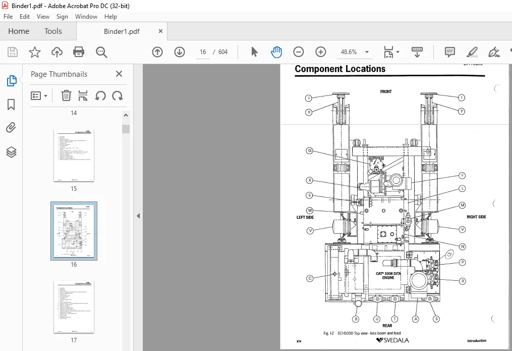
Component Locations xii
SAFETY SECTION 1
Overview of Potential Hazards 1-2
Safety Instructions 1-3
Before Operation 1-3
After Operation 1-3
Maintenance 14
Equipment Transfer 14
MAIN FRAME/TRACKS SECTION 2
Track Oscillation Cylinders 2-2
Removal 2-2
Installation 2-2
Track Tension Adjustment 2-3
Adjust track tension as follows: 2-3
Track Assembly 2-5
Separate Track Chain Assembly 2-5
Connect Track Assemblies 2-7
Front Idler & Recoil Spring 2-9
Front Idler & Recoil Spring – Removal 2-9
Front Idler & Recoil Spring – Replace 2-10
Front Idler Disassembly 2-11
Front Idler 2-11
Front Idler Assembly 2-13
Track Carrier Rollers 2-15
Track Carrier Rollers – Removal 2-15
Track Carrier Rollers – Replace 2-16
Duo-Cone Seals 2-17
Assembly And Installation of Conventional Duo-Cone Seals 2-17
Final Drive Oil 2-21
Lubrication Specification 2-21
Checking Oil Level in Final Drive 2-22
Changing Oil in Final Drive 2-22
Towing Procedure (late models) 2-24
Gear Drive Disconnect (machines with spacer) 2-24
Towing Procedure (early models) 2-26
Gear Drive Disconnect (early model machines with spring) 2-26
Final Drive Disengage Spacer Retrofit 2-28
Procedure for Installing Disengage Lockout Spacer 2-28
Final Drive Assembly 2-30
ii S)SVEDALA Introduction
BI116058
Table of Contents
MAIN FRAME/TRACKS SECTION 2
Final Drive – Removal from Track Frame 2-34
Final Drive Repair 2-34
Final Drive Motors 2-35
Motor Case Pressure 2-37
Motor—Removal-&-Installation-from-Planetary_Drive_.. ……. 2-37
Motor – Repair 2-37
POWER TRAIN SECTION 3
Hydraulic Pumps 3-2
Hydraulic Pumps – Removal and Installation 3-2
Hydraulic Pump – Repair 3-2
Hydraulic Pump Retrofit Procedure 3-3
Description of Procedure: 13
Hydraulic Pump – Repair 3-3
Rexroth Pump Installation 34
Parts List 3-5
Procedure for Replacing a PVD45 Vickers Pump with a AllVLO Rexroth Pump 3-6
Fuel System 3-12
Fuel Tank Maintenance 3-12
Fuel Filters – Every 250 Hours of Operation 3-13
Priming the Fuel System 3-13
Coolers 3-14
Engine Radiator – Capacity and Service 3-14
Coolant Specifications 3-15
Compressor Oil Cooler – Removal & Installation 3-16
Radiator/Oil Cooler – Removal & Installation 3-17
HYDRAULIC/ELECTRICAL SYSTEMS SECTION 4
Hydraulic System 4-2
Basic Hydraulic Schematic (Vickers Pumps) 4-3
Basic Hydraulic Schematic (Rexroth Pumps) 44
Tram Console with Boom Hosing 4-5
Hydraulic Schematic – Drill Console 4-6
Hydraulic Schematic – Cab 4-7
Rod Changer Piping 4-9
Boom Piping 4-10
Hydraulic Valves – Maintenance 4-11
Boom/Feed Pilot Valve 4-11
Pilot Tube Cleaning Instructions 4-11
Tram Pilot Valve 4-12
Pilot Tube Cleaning Instructions 4-12
Electrical Schematic – Base Machine 4-13
D.C. Schematic – Non-Cab Machine 4-16
Introduction %%SVEDALA Ili
BI116058
Table of Contents
HYDRAULIC/ELECTRICAL SYSTEMS SECTION 4
D.C. Schematic – Cab Machine 4-18
Wiring Diagram – Cab 4-22
Wire Number/Color Code Chart (Cab to Main Junction Box) 4-25
Wire Number/Color Code Chart (Inside Cab) 4-26
Wiring Diagram – Boom Control Panel 4-28
Wiring Diagram – Drill Control Panel 4-29
Wiring Diagram – Tram Control Panel 4-30
Wiring Diagram – Instrument Panel 4-31
AIR SYSTEM SECTION 5
Air Receiver Tank 5-2
Preventive Maintenance 5-2
Compressor Oil Separator Element: 5-2
Preventive Maintenance 5-2
Air Receiver Tank – Troubleshooting 5-4
Air System Components 5-6
Compressor Oil Piping 5-7
Thermostatic Bypass Valve 5-7
Air Valve Piping (cab machines) 5-8
Air Valve Piping (non-cab machines) 5-9
Compressor Assembly – 350 CFM 5-10
Compressor Unit – 350 CFM 5-11
Drive Coupling – Replacement 5-11
Compressor Assembly – 350 CFM 5-11
Air Compressor Drive Motor (fixed displacement) 5-12
General Description 5-12
Variable Displacement Motor Adjustment 5-13
Case Drain Pressure 5-13
400 CFM Option 5-14
Adjustments 5-15
BOOM & FEED COMPONENTS SECTION 6
Boom Lift Cylinder 6-2
Boom Lift Cylinder – Removal 6-2
Boom Lift Cylinder – Replace 6-3
Cylinder Bleeding Procedure and Final Installation: 6-3
Boom Swing Cylinder 6-4
Boom Swing Cylinder – Removal 6-4
Boom Swing Cylinder – Replace 6-5
Cylinder Bleeding Procedure and Final Installation: 6-5
Feed Dump Cylinder 6-6
Feed Dump Cylinder – Removal 6-6
Feed Dump Cylinder – Replace 6-7
iv VSVEDALA Introduction
BI116058
Table of Contents
BOOM & FEED COMPONENTS SECTION 6
Cylinder Bleeding Procedure and Final Installation: 6-7
Feed Swing Cylinder 6-8
Feed Swing Cylinder – Removal 6-9
Feed Swing Cylinder – Replace 6-11
Cylinder Bleeding Procedure and Final Installation: 6-11
Feed Extension Cylinder 6-12
Feed Extension Cylinder – Removal 6-13
Feed Extension Cylinder – Replace 6-15
Cylinder Bleeding Procedure and Final Installation: 6-15
Boom Shim/Wear Pad Replacement 6-16
Boom Wear Pads – Inspection 6-17
Feed and Feed Table – Removal from Boom 6-18
Inner Boom Tube – Removal 6-21
Rear Wear Pads and Shims – Installation 6-23
Front Wear Pads and Shims – Installation 6-25
Feed and Feed Table – Installation on Boom 6-26
Boom Wear Pads – Final Inspection 6-29
HPR2 Hydraulic Rock Drill 6-30
Removal from Feed 6-31
Installation on Feed 6-31
Mounting Slide Adjustment 6-32
Feed Chain Tension 6-33
Adjustment 6-33
PRESSURE SETTINGS & ADJUSTMENTS SECTION 7
Engine Adjustments 7-2
Engine Low Idle 7-2
Engine High Idle 7-2
Brake Valve Adjustments 74
Brake Valve Adjustment (with Vickers Main Pumps) 7-5
Brake Sequence Valve – Bench Test Procedure 7-6
Brake Valve Adjustment (with Rexroth Main Pumps) 7-7
Tram System 7-8
Description 7-8
Counterbalance Valve – Adjustment Procedure 7-9
Tram Counterbalance Valve – Bench Test Procedure 7-11
Tram Valve /Joystick Adjustments 7-12
Joystick Adjustment: 7-12
Adjustment Procedures & Troubleshooting 7-15
Tramming Adjustment 7-18
Feed/Boom Valve Adjustment 7-19
Main Pump Adjustments (Vickers PVD45) 7-20
Standby Pressure Adjustment 7-21
Introduction •%SVEDALA
BI116058
Table of Contents
PRESSURE SETTINGS & ADJUSTMENTS SECTION 7
Maximum Pressure and Differential Pressure Adjustment 7-23
Case Pressure 7-23
Main Pump Adjustments (Rexroth AllVLO) 7-24
Load Sense Pressure Adjustment 7-25
High Pressure Adjustment (machines with relief valves) 7-25
High Pressure Adjustment (machines without relief valves) 7-26
Pressure Reducing Valve Adjustment 7-27
Rotation Pump Circuit 7-28
Rotation Circuit 7-29
Adjustment Procedure 7-31
Case Drain 7-31
Drill & Feed Valve Adjustments 7-32
Drill & Feed Valve Pressure Settings 7-32
Drill (Hammer) Valve 7-32
Drill Rotation Valve 7-33
Feed Valve 7-33
Feed Pressure Override 7-33
Collaring Circuit Adjustment 7-34
Collaring Circuit 7-35
Anti-Jam / Collaring Circuit 7-36
Anti-Jam/Collaring Circuit Adjustment 7-38
Reverse Percussion Option 7-39
Description 7-39
Operating Principle 7-39
Maintenance 7-39
Reverse Percussion – Repair 741
Inspection 741
Adjustment 743
Dust Collector Assembly 7-44
Function of Dust Collector 745
Detailed Function of Components 745
Dust Collector Setup 746
Initial Start-up and Tuning 746
Dust Collector Valve – Adjustment 746
Air Pressure Regulator – Adjustment 747
Timer – Adjustment 748
Fan Speed. Adjustment 748
Filter Elements 7-50
Dust Collector Efficiency 7-50
Operational Variables 7-51
Fine Tuning 7-51
Manometer Setup Instructions 7-53
Timer Installation 7-54
vi 4%SVEDALA Introduction
BI116058
Table of Contents
PRESSURE SETTINGS & ADJUSTMENTS SECTION 7
To Set Timer 7-54
Control Circuit 7-55
Fan Removal and Installation 7-56
Dust Collector Troubleshooting 7-57
Centralizer_Adjustment 7-59
Vertical Indicator 7-60
Description 7-60
Vertical Adjustment 7-60
Wiring 7-61
Troubleshooting 7-61
Rod Changer Valve 7-62
Pressure Adjustments 7-62
3 Bank Valve – Cab/Drill Console 7-64
Pressure Adjustments 7-64
Coupling Grease System 7-66
Adjustments 7-67
Daily Maintenance 7-67
Troubleshooting 7-68
Air Pressure Regulator 7-68
Filter Assembly 7-69
Lubricator Assembly 7-70
Operation 7-71
3-Way Air Valve – Maintenance 7-72
Auxiliary Operator – Maintenance 7-73
Auxiliary Operator – Adjustment 7-74
3-Way Air Valve – “CF” Solenoid with Junction Box 7-75
Air Powered Grease Pump 7-76
Pump Repair 7-76
VENDOR SERVICE INFORMATION SECTION 8
Index to Service Information 8-2
HYDRAULIC ROCK DRILL REPAIR SECTION 9
HPR2 Hydraulic Rock Drill Service Manual (part no. 0408860)
LUBRICATION & TORQUE SPECIFICATIONS SECTION 10
Selection of Hydraulic Oil 10-2
Lubrication and Inspection 10-3
Preventive Maintenance Chart 10-4
Bolt Torque Specifications 10-6
PLEASE NOTE:
- This is not a physical manual but a digital manual – meaning no physical copy will be couriered to you. The manual can be yours in the next 2 mins as once you make the payment, you will be directed to the download page IMMEDIATELY.
- This is the same manual used by the dealers inorder to diagnose your vehicle of its faults.
- Require some other service manual or have any queries: please WRITE to us at [email protected]
S.V