CAT Scoop 488-6 & 488L UN-A-TRAC Operator Manual PDF
$27.95
CAT Scoop 488-6 and 488L UN-A-TRAC® Operation Manual – PDF DOWNLOAD
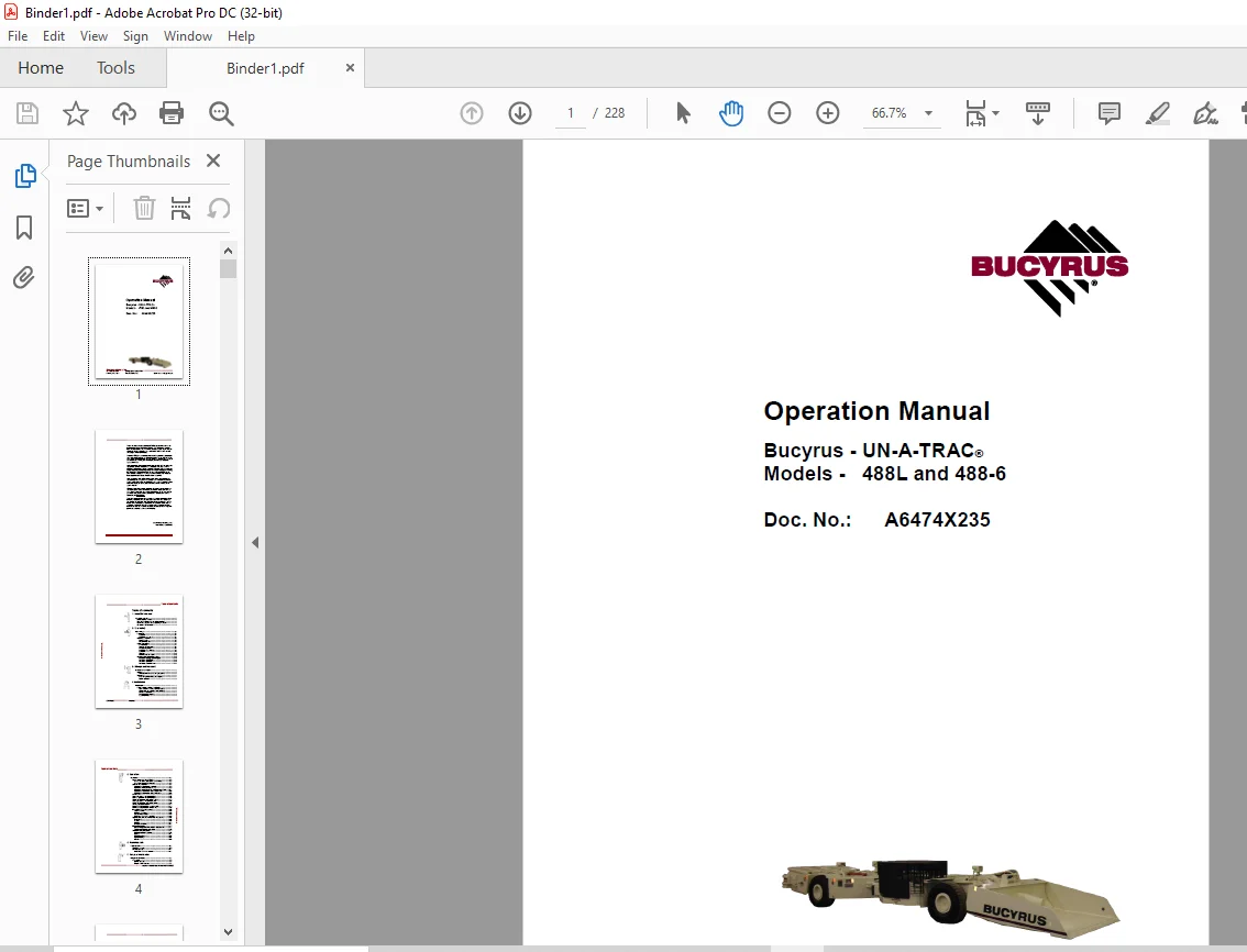
CAT Scoop 488-6 and 488L UN-A-TRAC® Operation Manual
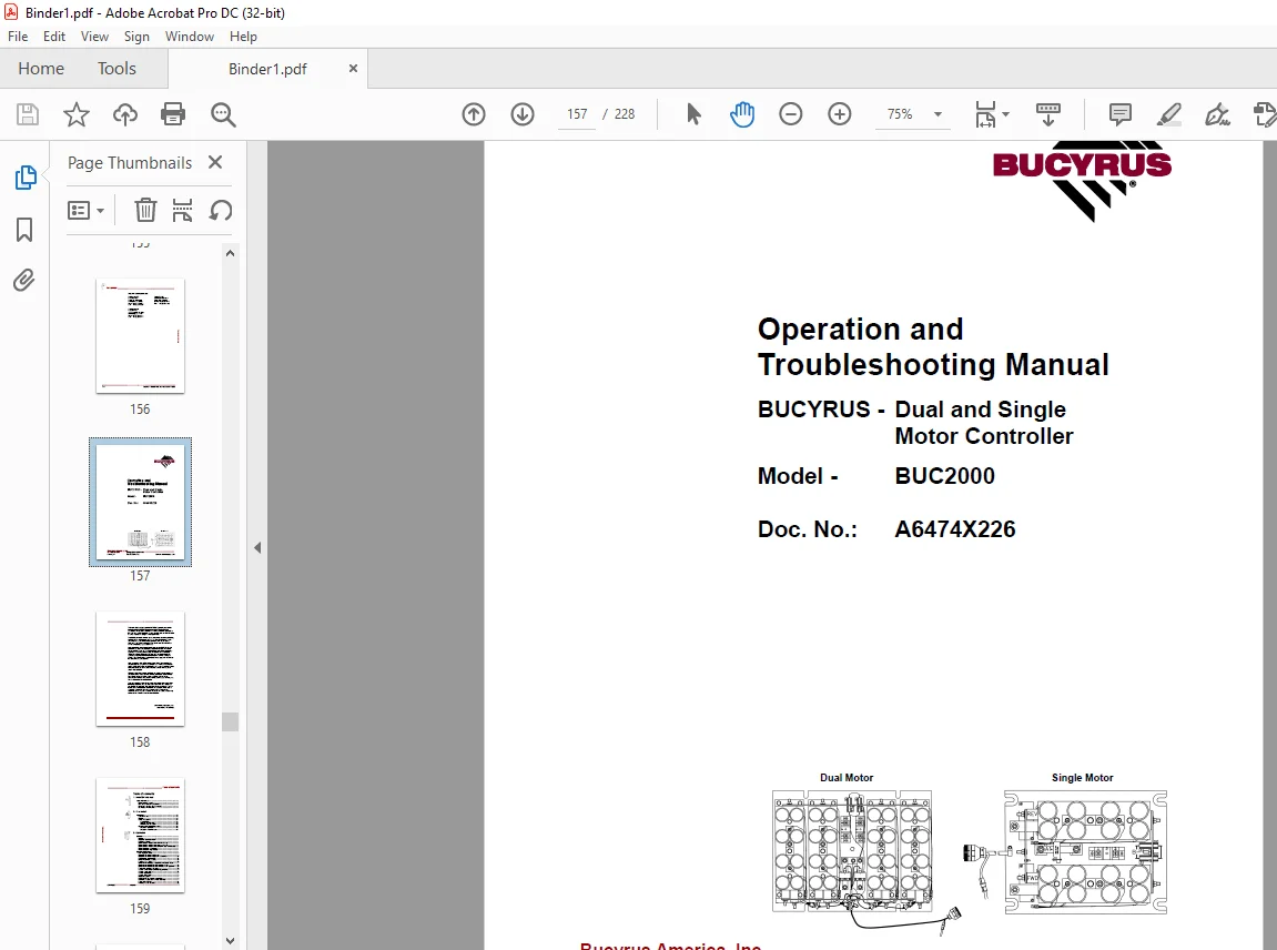
CAT Scoop BUC2000 Dual and Single Motor Controller Operation and Troubleshooting Manual
Description
CAT Scoop 488-6 and 488L UN-A-TRAC® Operation Manual – PDF DOWNLOAD
FILE DETAILS:
CAT Scoop 488-6 and 488L UN-A-TRAC® Operation Manual – PDF DOWNLOAD
Language : English
Pages :228
Downloadable : Yes
File Type : PDF
DESCRIPTION:
CAT Scoop 488-6 and 488L UN-A-TRAC® Operation Manual – PDF DOWNLOAD
CAT Scoop 488-6 and 488L UN-A-TRAC® Operation Manual
CAT Scoop BUC2000 Dual and Single Motor Controller Operation and Troubleshooting Manual
About this manual
This chapter provides important information making it easier for you to use this manual. You will also be given information on the structure of the manual and the symbols and characters used
for the type of equipment or machine used.
Bucyrus Model 488-6 UN-A-TRAC®
Model 488L UN-A-TRAC®
Serial No.: N/A
and is only permitted to be used for equipment of this type
This operating manual is intended for those persons who work with or
on the machine.
Every person working on the face or in the intersection between face
and entry or in the entry must read this operating manual.
This includes persons who:
■ are in charge of transport
■ perform assembly / disassembly work
■ operate the machine
■ eliminate faults
■ perform daily routine work on the face or in the entry
■ perform maintenance work
■ perform repair work
IMAGES PREVIEW OF THE MANUAL:
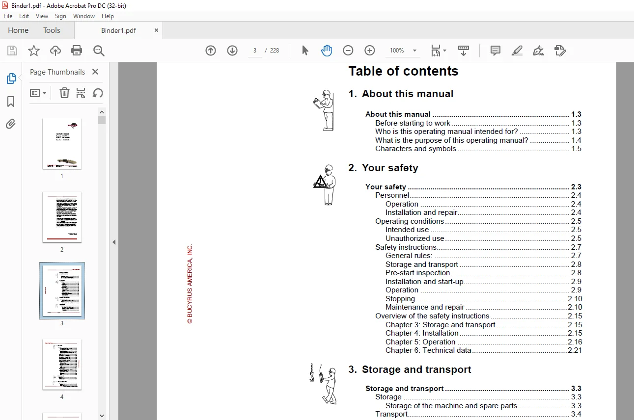
TABLE OF CONTENTS:
CAT Scoop 488-6 and 488L UN-A-TRAC® Operation Manual – PDF DOWNLOAD
1 About this manual
About this manual 1 3
Before starting to work 1 3
Who is this operating manual intended for? 1 3
What is the purpose of this operating manual? 1 4
Characters and symbols 1 5
2 Your safety
Your safety 2 3
Personnel 2 4
Operation 2 4
Installation and repair 2 4
Operating conditions 2 5
Intended use 2 5
Unauthorized use 2 5
Safety instructions 2 7
General rules: 2 7
Storage and transport 2 8
Pre-start inspection 2 8
Installation and start-up 2 9
Operation 2 9
Stopping 2 10
Maintenance and repair 2 10
Overview of the safety instructions 2 15
Chapter 3: Storage and transport 2 15
Chapter 4: Installation 2 15
Chapter 5: Operation 2 16
Chapter 6: Technical data 2 21
3 Storage and transport
Storage and transport 3 3
Storage 3 3
Storage of the machine and spare parts 3 3
Transport 3 4
Load units, dimensions, and weights 3 4
Before transport 3 5
4 Installation
Installation 4 3
Points to observe prior to installation 4 3
Who is allowed to carry out installation? 4 3
Which tools are required for installation? 4 3
Notes on installation 4 4
Pre-installation check list 4 5
Safety features 4 6
Table of contents _________________________________________________
_________________________________________________________________
Bucyrus – Models 488L and 488-6 UN-A-TRAC®
© BUCYRUS AMERICA, INC
5 Operation
Operation 5 3
How to operate the UN-A-TRAC® 5 3
Who is allowed to operate the UN-A-TRAC® 5 3
When can operation be started? 5 3
Controls and indicators 5 4
Operator’s compartment – common 5 6
Hydraulic control panel (standard) 5 9
Hydraulic control panel (with vertical lift and QDS) 5 11
Operator’s compartment with control handle 5 15
Operator’s compartment with control station 5 18
Hazard zone 5 20
Starting procedure with control handle 5 21
Machine operation with control handle 5 22
Shutdown procedure with control handle 5 25
Starting procedure with control station 5 27
Shutdown procedure with control station 5 30
Towing a disabled machine 5 31
Battery change procedure (ground level) 5 32
Battery change procedure (vertical lift) 5 38
Instructions on the maintenance 5 45
Important notes 5 45
Before maintenance 5 45
Critical torque values 5 46
Lubricants, fluids and capacities 5 46
Specific lubrication and maintenance instructions 5 51
Every shift 5 51
Weekly 5 52
Monthly 5 53
Every three months 5 64
Major maintenance 5 71
Drive motor/gearbox removal and replacement 5 71
Tire/wheel installation procedure 5 73
Troubleshooting procedures 5 77
Hydraulic system (general) 5 78
Brakes 5 81
Hydraulic cylinders 5 83
Hydraulic pump 5 84
Valves 5 86
6 Technical data
Technical data 6 3
Tightening torques 6 5
Permissible data 6 11
Lubrication fluids and greases 6 11
7 For your information
For your information 7 3
Our service 7 3
Service address 7 3
CAT Scoop BUC2000 Dual and Single Motor Controller Operation and Troubleshooting Manual
Table of contents
1 About this manual
About this manual 1 3
Before starting to work 1 3
Who is this manual intended for? 1 3
What is the purpose of this manual? 1 4
Characters and symbols 1 5
2 Your safety
Your safety 2 3
State of the art 2 3
Repair 2 3
Safety instructions 2 4
General rules 2 4
Storage and transport 2 5
Maintenance and repair 2 6
Overview of the safety instructions 2 8
Chapter 3: Operation 2 8
Chapter 4: Technical data 2 8
3 Operation
Operation 3 3
History 3 3
Simplified BUC2000 circuit 3 4
Voltage vs speed 3 4
Flywheel diode motor current (forward mode) 3 5
Flywheel diode motor current (reverse mode) 3 5
Flywheel diode motor current (direction does not change) 3 6
Flywheel current (low speed) 3 7
Flywheel current (high speed) 3 7
General specifications 3 8
Data logging features 3 11
Microprocessor based logic card 3 12
Microprocessor based logic card diagnostics 3 13
Configuration jumper table 3 14
Optional dashboard display 3 15
Fault message chart 3 16
Optional hand held diag calibration unit security levels 3 17
Optional hand held diagnostics calibration unit 3 18
Optional hand held diagnostics calibration unit operation 3 19
Personality adjustment procedure 3 19
Traction personalities (controller adjustments) 3 20
Traction status display 3 21
Traction test display 3 23
Traction BDI display 3 23
Error code legend 3 24
IGBT panels and harness assemblies 3 25
Dashboard display and harness assembly 3 31
Panel wiring harness 3 34
Vehicle direction of travel 3 35
BUC2000— Dual and Single Motor Solid State Controllers
© BUCYRUS AMERICA, INC
Troubleshooting 3 37
IGBT and diode measurements 3 38
IGBT measurements 3 39
Diode measurements 3 40
Panel measurements 3 42
Driver measurements 3 43
Schematics 3 44
4 Tightening torques
Tightening torques 4 3
5 For your information
For your information 5 3
Our service 5 3
Service address 5 3
Rebuild facility address 5 4
Customer Support: [email protected]
S.M