CAT Scoop 488L and 488-6 UN-A-TRAC® Operation Manual A6474X235 – PDF DOWNLOAD
$28.95
CAT Scoop 488L and 488-6 UN-A-TRAC® Operation Manual A6474X235 – PDF DOWNLOAD
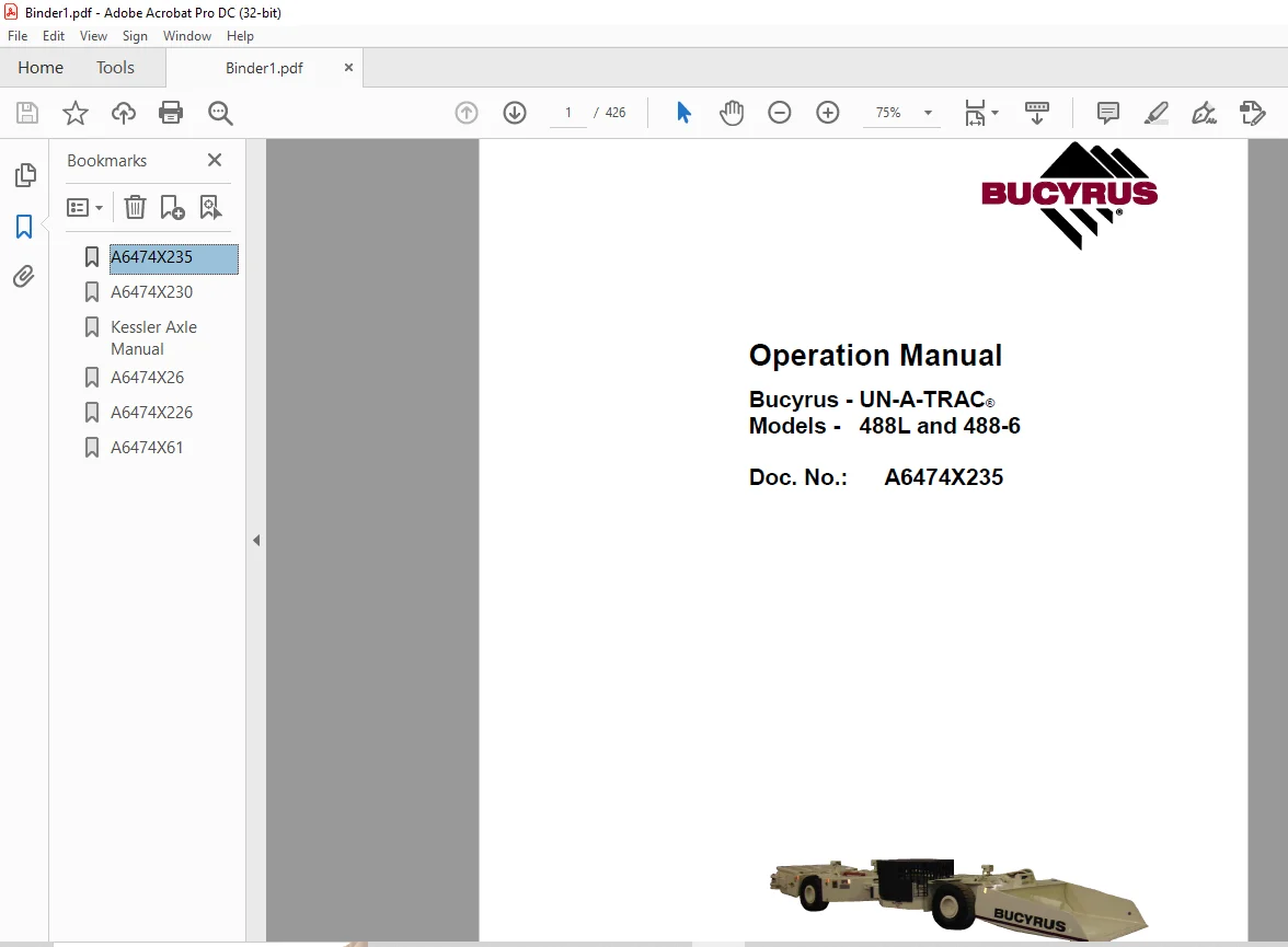
1.CAT Scoop 488L and 488-6 UN-A-TRAC® Operation Manual A6474X235
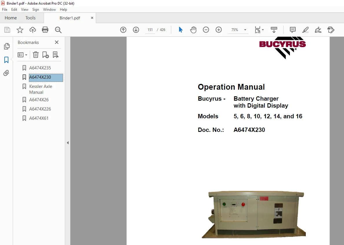
2.CAT SCOOP 5, 6, 8, 10, 12, 14, and 16 Battery Charger with Digital Display Operation Manual
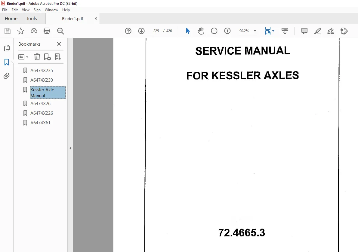
3.CAT SCOOP Kessler Axle Service Manual72.4665.3
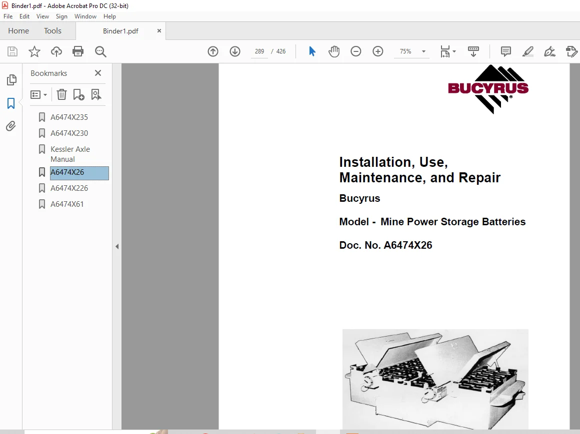
4.CAT SCOOP Mine Power Storage Batteries Installation, Use,Maintenance, and Repair Manual
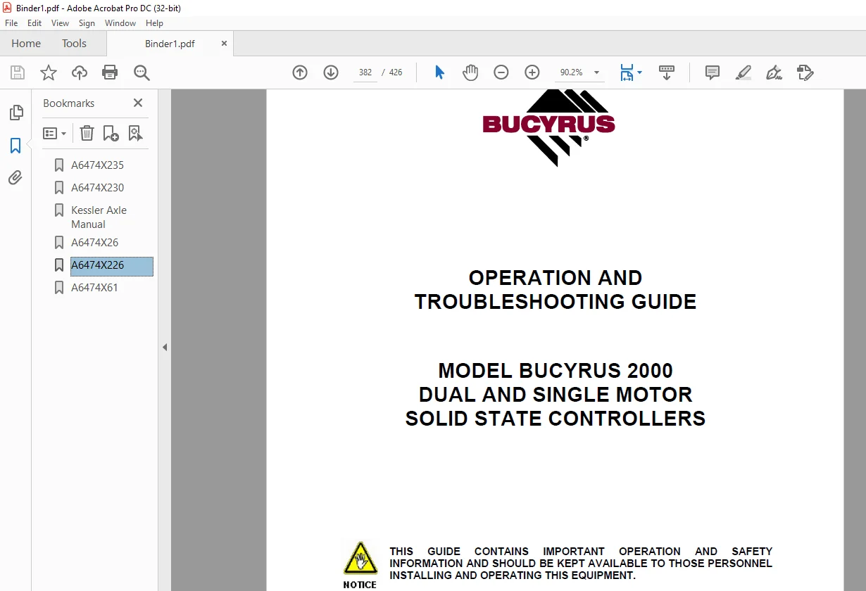
5.CAT SCOOP 2000 DUAL AND SINGLE MOTOR SOLID STATE CONTROLLERS OPERATION AND TROUBLESHOOTING GUIDE Manual
Description
CAT Scoop 488L and 488-6 UN-A-TRAC® Operation Manual A6474X235 – PDF DOWNLOAD
FILE DETAILS:
CAT Scoop 488L and 488-6 UN-A-TRAC® Operation Manual A6474X235 – PDF DOWNLOAD
Language : English
Pages : 426
Downloadable : Yes
File Type : PDF
IMAGES PREVIEW OF THE MANUAL:
DESCRIPTION:
CAT Scoop 488L and 488-6 UN-A-TRAC® Operation Manual A6474X235 – PDF DOWNLOAD
1.CAT Scoop 488L and 488-6 UN-A-TRAC® Operation Manual A6474X235
2.CAT SCOOP 5, 6, 8, 10, 12, 14, and 16 Battery Charger with Digital Display Operation Manual
3.CAT SCOOP Kessler Axle Service Manual72.4665.3
4.CAT SCOOP Mine Power Storage Batteries Installation, Use,Maintenance, and Repair Manual
5.CAT SCOOP 2000 DUAL AND SINGLE MOTOR SOLID STATE CONTROLLERS OPERATION AND TROUBLESHOOTING GUIDE Manual
- This manual is intended to provide GENERAL product information for the Model 488-6 and 488L UN-A-TRAC® . The illustrations, descriptions and procedures contained in this publication apply only to THESE machines. Bucyrus America, Inc. reserves the right to revise models and designs without prior notice.
- This UN-A-TRAC® was manufactured under the guidelines, procedures and requirements of the U. S. Federal Coal Mine Health and Safety Act, Code of Federal Regulations, Title 30, Chapter 1, Subpart 0, Part 75 for underground coal mines, and other applicable non-U.S. regulatory agency standards. At the completion of the manufacturing process, this unit was issued the appropriate approval numbers and nameplates indicating it met the technical requirements of these regulatory agencies. Any change to the design or structure of this unit, without the consent of Bucyrus America, Inc.
- and these regulatory agencies, or any repair or replacement of parts contrary to Bucyrus America, Inc.’s instructions, may invalidate these approvals and render this unit unsafe to operate. Strict compliance with all Federal and State Mining laws, regulations and practices regarding the safe operation and maintenance of underground mining equipment and strict adherence to the instructions in this manual is necessary for the personal safety of those working on or around this unit.
- While this manual attempts to anticipate the most important operations and maintenance needs for this unit, unforeseen circumstances may arise that have not been addressed in this manual. If any concerns or questions arise, please contact your Bucyrus America. Inc. Service Representative immediately.
- This work contains information protected under trade secret and other intellectual property laws, and is protected under the U. S. Copyright Act of 1976, as amended. This work is provided under license and the license is non-transferable. Distribution and access is limited only to authorized personnel. Disclosure, reproduction, distribution or unauthorized use may be a violation of federal and state laws and may subject the unauthorized user to criminal liability.
Before starting to work
About this manual
This chapter provides important information making it easier for you to
use this manual. You will also be given information on the structure of
the manual and the symbols and characters used.
Before starting to work
applicable operating manual: Take care to ensure that the operating manual available to you is applicable for the type of equipment or machine used.
machine type: This operating manual is intended for:
Bucyrus America, Inc. – Model, 488-6DM UN-A-TRAC ® Serial No.: N/A
and is only permitted to be used for equipment of this type.
new operation manual: The operating manual must be accessible at all times to all persons working on or with the machine. It should, if possible, always be available at the place of operation. Send for a new operation manual immediately if the present manual is no longer complete or has become illegible
Who is this operating manual intended for?
This operating manual is intended for those persons who work with or
on the machine.
Every person working on the face or in the intersection between face
and entry or in the entry must read this operating manual.
This includes persons who:
■ are in charge of transport
■ prepare the rise heading
■ perform assembly / disassembly work
■ operate the machine
■ eliminate faults
■ perform daily routine work on the face or in the entry
■ perform maintenance work
■ perform repair work
supervisory personnel who:
■ initiate and/or
■ supervise the activities just indicated
TABLE OF CONTENTS:
CAT Scoop 488L and 488-6 UN-A-TRAC® Operation Manual A6474X235 – PDF DOWNLOAD
Table of contents
1 About this manual
About this manual 1 3
Before starting to work 1 3
Who is this operating manual intended for? 1 3
What is the purpose of this operating manual? 1 4
Characters and symbols 1 5
2 Your safety
Your safety 2 3
Personnel 2 4
Operation 2 4
Installation and repair 2 4
Operating conditions 2 5
Intended use 2 5
Unauthorized use 2 5
Safety instructions 2 7
General rules: 2 7
Storage and transport 2 8
Pre-start inspection 2 8
Installation and start-up 2 9
Operation 2 9
Stopping 2 10
Maintenance and repair 2 10
Overview of the safety instructions 2 15
Chapter 3: Storage and transport 2 15
Chapter 4: Installation 2 15
Chapter 5: Operation 2 16
Chapter 6: Technical data 2 21
3 Storage and transport
Storage and transport 3 3
Storage 3 3
Storage of the machine and spare parts 3 3
Transport 3 4
Load units, dimensions, and weights 3 4
Before transport 3 5
4 Installation
Installation 4 3
Points to observe prior to installation 4 3
Who is allowed to carry out installation? 4 3
Which tools are required for installation? 4 3
Notes on installation 4 4
Pre-installation check list 4 5
Safety features 4 6
5 Operation
Operation 5 3
How to operate the UN-A-TRAC® 5 3
Who is allowed to operate the UN-A-TRAC® 5 3
When can operation be started? 5 3
Controls and indicators 5 4
Operator’s compartment – common 5 6
Hydraulic control panel (standard) 5 9
Hydraulic control panel (with vertical lift and QDS) 5 11
Operator’s compartment with control handle 5 15
Operator’s compartment with control station 5 18
Hazard zone 5 20
Starting procedure with control handle 5 21
Machine operation with control handle 5 22
Shutdown procedure with control handle 5 25
Starting procedure with control station 5 27
Shutdown procedure with control station 5 30
Towing a disabled machine 5 31
Battery change procedure 5 32
Instructions on the maintenance 5 39
Important notes 5 39
Before maintenance 5 39
Critical torque values 5 41
Lubricants, fluids and capacities 5 41
Specific lubrication and maintenance instructions 5 45
Every shift 5 45
Weekly 5 46
Monthly 5 57
Every three months 5 58
Major maintenance 5 65
Drive motor/gearbox removal and replacement 5 65
Tire/wheel installation procedure 5 67
Troubleshooting procedures 5 71
Hydraulic system (general) 5 72
Brakes 5 75
Hydraulic cylinders 5 77
Hydraulic pump 5 78
Valves 5 80
6 Technical data
Technical data 6 3
Tightening torques 6 5
Permissible data 6 11
Lubrication fluids and greases 6 11
7 For your information
For your information 7 3
Our service 7 3
Service address 7 3
CAT SCOOP 5, 6, 8, 10, 12, 14, and 16 Battery Charger with Digital Display Operation Manual
Table of contents
1 About this manual
About this manual 1 3
Before starting to work 1 3
Who is this operating manual intended for? 1 3
What is the purpose of this operating manual? 1 4
Characters and symbols 1 5
2 Your safety
Your safety 2 3
Personnel 2 4
Operation 2 4
Installation and repair 2 4
Operating conditions 2 5
Intended use 2 5
Unauthorized use 2 5
Safety instructions 2 7
General rules: 2 7
General precautions 2 8
Risk of explosive gasses 2 8
Personal precautions 2 9
Preparing to charge precautions 2 9
Unit location precautions 2 10
Major hazards 2 10
Storage and transport 2 11
Installation and start-up 2 12
Operation 2 12
Maintenance and repair 2 12
Overview of the safety instructions 2 15
Chapter 2: Your safety 2 15
Chapter 3: Storage and transport 2 15
Chapter 4: Installation 2 15
Chapter 5: Operation 2 16
Chapter 6: Technical data 2 16
3 Storage and transport
Storage and transport 3 3
Storage 3 3
Storage of the machine and spare parts 3 3
Transport 3 4
Load units; dimensions and weights 3 4
Before transport 3 4
4 Installation
Installation 4 3
Points to observe prior to installation 4 3
Who is allowed to carry out installation? 4 3
Which tools are required for installation? 4 3
Notes on installation 4 3
Pre-installation check list 4 4
General information 4 5
Safety features 4 6
Standard features 4 8
Environmental ratings 4 8
Ratings and specifications 4 9
Minimum wire size 4 10
Electrical connections and field wiring 4 11
Ground integrity (optional) 4 12
5 Operation
Operation 5 3
How to operate the battery charger 5 3
Who is allowed to operate the battery charger 5 3
When can charging be started? 5 3
Controls and indicators 5 4
Startup procedure 5 5
Fault codes 5 6
Adjustments 5 7
Circuit operation 5 7
Instructions on the maintenance 5 13
Important notes 5 13
Before maintenance 5 13
General maintenance procedures 5 14
Troubleshooting procedures 5 15
General inspection 5 15
Service information 5 15
Troubleshooting information 5 16
Ground short circuit test 5 17
Troubleshooting and replacing power silicon diodes 5 17
Checking capacitors 5 18
6 Technical data
Technical data 6 3
Components of the battery charger 6 3
7 For your information
For your information 7 3
Our service 7 3
Service address 7 3
Rebuild facility address 7 4
CAT SCOOP Kessler Axle Service Manual72.4665.3
1 About this manual
About this manual 1 3
Before starting to work 1 3
Who is this operating manual intended for? 1 3
What is the purpose of this operating manual? 1 4
Characters and symbols 1 5
2 Your safety
Your safety 2 3
Personnel 2 4
Operation 2 4
Installation and repair 2 4
Operating conditions 2 5
Intended use 2 5
Unauthorized use 2 5
Safety instructions 2 7
General rules 2 7
Storage and transport 2 7
Pre-start inspection 2 8
Operation 2 8
Maintenance and repair 2 9
Battery hazards 2 10
Safety procedures 2 11
Federal standards 2 11
While handling batteries 2 11
While charging batteries 2 12
While handling acids 2 13
While servicing or repairing batteries 2 14
Overview of the safety instructions 2 15
Chapter 3: Storage and transport 2 15
Chapter 4: Installation 2 15
Chapter 5: Operation 2 15
3 Storage and transport
Storage and transport 3 3
Storage 3 3
Storage methods 3 3
Charged and wet batteries 3 3’
Charged and dry batteries 3 3
Transport 3 4
Load units 3 4
Shipment 3 4
Unpacking upon receipt 3 5
4 Installation
Installation 4 3
Points to observe prior to installation 4 3
Who is allowed to carry out installation? 4 3
Which tools are required for installation? 4 3
Notes on installation 4 4
Pre-installation check list 4 5
5 Operation
Operation 5 3
Definitions 5 3
Descriptions and construction 5 3
Charging 5 7
Principles of operation 5 11
Fundamentals of cycling 5 11
Ampere-hour capacity 5 12
Voltage 5 12
Rated capacity 5 12
Sulfation 5 13
Operating cycle 5 13
Service life 5 13
Temperature 5 13
Preparation for use 5 15
Establishing battery requirements 5 15
Acid to water proportions 5 15
Charged and wet batteries 5 15
Instructions on the maintenance 5 17
Important notes 5 17
General 5 17
Specific maintenance instructions 5 19
Every shift 5 19
Weekly 5 21
Monthly 5 22
Annually 5 22
Recordkeeping 5 22
Troubleshooting procedures 5 25
Instructions on the adjustment procedures 5 29
Electrolyte specific gravity 5 29
Restoring a sulfated battery 5 30
Excessive self discharge correction 5 31
Test discharge 5 31
Replacement of parts 5 33
Purging gas 5 33
Removing intercell connectors 5 33
Removing a complete cell 5 34
Removing an element 5 34
Replacing a cell in a battery 5 36
Replacing a cell cover 5 37
Sealing compound and lead bushing design 5 37
Epoxy seal and nut design 5 38
Heat bonded plastic cover-to-jar design 5 38
6 Technical data
Tightening torques 6 3
7 For your information
For your information 7 3
Our service 7 3
Service address 7 3
Rebuild facility address 7 4
PREFACE 2
SYMBOLS AND SPECIAL NOTATIONS 3
MAJOR HAZARDS 5
SAFETY PRECAUTIONS AND GUIDELINES 6
OVERVIEW 6
MAINTENANCE 6
INTRODUCTION 7
BUCYRUS 2000: INNOVATIVE SPEED CONTROL BY BUCYRUS AMERICA, INC 7
GENERAL SPECIFICATIONS 12
FAIL-SAFE OPERATION WILL INCLUDE THE FOLLOWING: 12
DESCRIPTION OF FEATURES 13
BUCYRUS 2000 MOTOR CONTROLLER CONSIST OF: 13
BUCYRUS 2000 MOTOR IGBT PANEL (POWER CONNECTIONS) 13
MICROPROCESSOR BASED LOGIC CARD (CONTROL INPUTS) 13
CONFIGURATION JUMPER TABLE 15
OPTIONAL DASHBOARD DISPLAY FEATURES (SEE FIGURE 9) 15
FAULT MESSAGE CHART 16
OPTIONAL HAND HELD DIAGNOSTICS/CALIBRATOR UNIT 18
PERSONALITY ADJUSTMENT PROCEDURE 19
TRACTION PERSONALITIES (CONTROLLER ADJUSTMENTS) 19
TRACTION STATUS DISPLAY 21
TRACTION TEST DISPLAY 23
TRACTION BDI DISPLAY 24
ERROR CODE LEGEND (STATUS DISPLAY) 25
TROUBLESHOOTING 26
IGBTMEASUREMENTS 27
INDIVIDUAL IGBT MEASUREMENTS 28
DIODEMEASUREMENTS 29
DIODEMEASUREMENTS 30
PANEL MEASUREMENTS 31
DRIVER MEASUREMENTS 32
IGBT DUAL MOTOR PANEL, FIGURE 16 34
IGBT SINGLEMOTOR PANEL,FIGURE 17 35
IGBT HEAT SINK ASSEMBLY, FIGURE 18 36
SINGLE MOTOR PANEL HARNESS ASSEMBLY, FIGURE 19 37
DUAL MOTOR PANEL HARNESS ASSEMBLY, FIGURE 20 38
DASHBOARD DISPLAY, FIGURE 21 39
DUAL “Y” HARNESS, FIGURE 22 40
HARNESS FOR DASHBOARD DISPLAY, FIGURE 23 41
CALIBRATOR UNIT, FIGURE 24 42
BUCYRUS 2000 PUMPMOTOR SHUNT, FIGURE 25 42
BUCYRUS 2000 PANELWIRING HARNESS, FIGURE 26 43
Need help? Contact: [email protected]
S.M