Cat SD 250 Hydra-Trac Self Contained Hydraulic Track Drill Service Manual – PDF DOWNLOAD
Original price was: $98.95.$39.95Current price is: $39.95.
Cat SD 250 Hydra-Trac Self Contained Hydraulic Track Drill Service Manual – PDF DOWNLOAD
Description
Cat SD 250 Hydra-Trac Self Contained Hydraulic Track Drill Service Manual – PDF DOWNLOAD
CAT SD 250 HYDRA-TRAC SELF CONTAINED HYDRAULIC TRACK DRILL SERVICE MANUAL – PDF DOWNLOAD:
IMAGES PREVIEW OF THE MANUAL:


DESCRIPTION:
Cat SD 250 Hydra-Trac Self Contained Hydraulic Track Drill Service Manual – PDF DOWNLOAD
Introduction :
This manual contains instructions regarding operation of the Model SD 250 Hydra-Trac® track drill carrier. lt is intended to help you understand how the system operates and the precautions that should Ье observed. Read understand this manual before operating or servicing this unit. This manual must Ье read and interpreted to non-English speaking personnel. Кеер it handy for future reference.
1. IDENTIFICATION OF ТНЕ MACHINE
Always furnish the Svedala Drilling Model Number and Serial Number when ordering parts. This information is found оп the machine nameplate (see page 1).
2. PART NUMBER AND DESCRIPTION
In addition to the Serial Number, always give the part number and description of each part ordered. 11 there is any douЫ as to the correct part number and description, furnish а dimensioned sketch or return the part to Ье replaced, transportation charges prepaid.
З. SHIPMENT
Unless otherwise instructed, all shipments will Ье made via motor freight collect or UPS prepaid and charged оп our invoice. Shipments cannot Ье made оп open account until your credit has
been approved Ьу our accounting department.
TABLE OF CONTENTS:
Cat SD 250 Hydra-Trac Self Contained Hydraulic Track Drill Service Manual – PDF DOWNLOAD
INТRODUCTION
Parts ordering and Product Support ii
General Description х
Component Location (non-caЫ х
US/ Metric Conversions xii
Glossary of Terms xiv
SAFEТY SECTION 1
Overview of Potential Hazards 1-2
Safety lnstructions : 1-3
Before Operation 1-3
After Operation 1-3
Maintenance 1-4
Equipment Transfer 1-4
MAIN FRAME/ТRACKS SECTION 2
Track Oscillation Cylinders 2-2
Removal 2-2
Repair 2-2
lnstallation 2-2
Track Maintenance 2-3
ldler, Track Rollers and Support Rollers 2-3
Final Drive 2-3
After а long period of standstill 2-3
After а short period of operation 2-3
After а long period of operation 2-3
Track Tension Adjustment 2-4
lf track is too tight 2-4
lf track is too loose 2-4
Proper Track Tension 2-4
Metric Bolt Тo rque Specifications 2-5
Track DisassemЫy 2-6
Separate Track Chain AssemЫy 2-6
Track Link Repair 2-7
Track Link AssemЫy 2-9
Track Shoes 2-1 О
Track Shoe – Mounting to Track Chain 2-1 О
Direct Torque Method 2-11
Torque Turn Method 2-11
Track Shoe – Retightening 2-11
Track Shoe Bolt Torque (Direct Torque Method) 2-12
Track Shoe Bolt Torque (Torque Turn Method) 2-13
lntroduction ??SYEDALA iii
BI615909
ТаЫе of Contents
Track AssemЫy 2-14
Track Chain & Shoe – AssemЫy & lnstallation 2-14
ldler Unit 2-16
General Description 2-16
ldler and Tensioner AssemЫy , 2-17
ldler Unit Removal 2-18
Removal and DisassemЬly 2-18
ldler Unit – AssemЫy lnstructions 2-19
AssemЬly and lnstallation 2-19
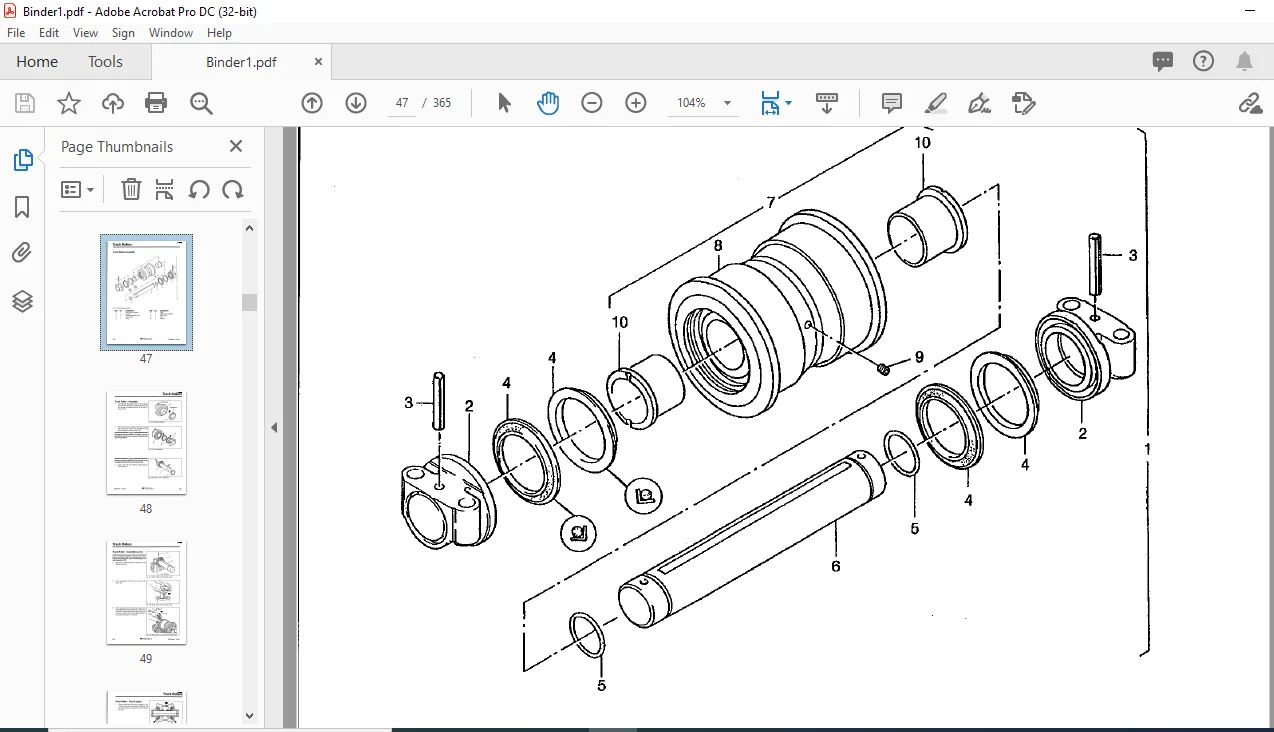
Track Rollers 2-23
General Description 2-23
Removal & DisassemЫy 2-23
Track Roller AssemЫy 2-24
Track Roller – Test & lnstall 2-27
Support Roller 2-29
General Description 2-29
Removal & DisassemЫy 2-29
Support Roller AssemЫy 2-30
Final Drive 2-34
Towing Procedure 2-34
Final Drive Operation and Maintenace Manual end of section
POWER TRAIN SECTION З
Engine 3-2
Specifications 3-2
Oil Filters 3-3
Air Filter 3-4
Engine Removal and lnstallation 3-5
Fuel System 3-6
Fuel Tank 3-6
Fuel System – Priming 3-7
Fuel;Water Separator 3-7
Fuel Filter 3-7
Radiator/Oil Coolers 3-8
lnspection and Maintenance 3-8
Hydraulic Oil Cooler 3-9
T hermostat Valve Operation 3-9
Removal of Radiator/Oil Coolers 3-9
Coolant Specifications 3-10
Hydraulic Pump 3-11
Pump Removal 3-11
Pump Repair 3-11
Pump lnstallation 3-11
PVH Piston Pump Overhaul Manual follows page 3-12
iv ?,SVEDALA introduction
BI615909
ТаЫе of Contents
Pump Drive 3-13
Pump Drive Removal and lnstallation 3-13
Pump Drive DisassemЬly 3-14
lnspection and Repair: , , , , , , , , , , , , , , , 3-14
AssemЫy: 3-15
Lubrication: , , , , , , , , , 3-15
Сапору 3-16
Removal of Сапору 3-16
ELECTRICAL AND HYDRAULIC SYSTEMS SECTION 4
Electrical Schematic (Cold Start) 4-2
Electrical Schematic (Starting) , 4-4
Electrical Schematic (Shutdown) 4-6
Electrical Schematic (Hourmeter) 4-8
Electrical Schematic (Throttle) 4-9
Electrical Schematic (24VDC Power) 4-10
Electrical Schematic (Remote Control) 4-11
Electrical Schematic (Tram Control) 4-12
Electrical Schematic (Drilling Mode) 4-14
Electrical Schematic (Rod Changing Mode) 4-16
Electrical Schematic (24VDC Power) 4-18
Electrical Schematic (поп-саЬ machines) 4-19
Electrical Schematic (саЬ machines) 4-22
Hydraulic Schematic 4-26
Hydraulic Cylinder Repair 4-28
Texas Hydrau/ics Maintenance Manual end of section
AIR SYSTEM SECTION 5
Air Compressor Air Filter 5-2
Air Compressor Oil and Filter 5-3
Changing Oil Filter 5-3
Adding Oil 5-3
Changing Oil 5-3
Compressor Oil Separator Element 5-4
Removal 5-4
lnstallation 5-4
Discharge Valve 5-5
Air Compressor Removal and lnstallation 5-6
Removal from Machine 5-6
lnstallation 5-6
Drive Belt Tensioning 5-6
Air Compressor Removal & lnstallation 5-6
Air Compressor Specifications 5-7
lntroduction 5-7
Technical Data 5-7
lntroduction ?YSVEDALA V
BI615909
ТаЫе of Contents
Air Compressor AssemЫy 5-8
Compressor Repair 5-9
Air lnlet Valve AssemЫy 5-9
Air End AssemЬly 5-10
Before Starting Repair Work 5-1 О
Special Tools 5-11
DisassemЫy Procedure 5-11
lnspection 5-12
AssemЬly Procedure: 5-13
Detergent System (optional} 5-14
Servicing the “У” Strainer 5-14
Detergent System F reeze Protection 5-15
ВООМ & FEED COMPONENTS SECTION 6
Boom Lift Cylinder 6-2
Removal 6-2
Repair 6-2
Replace 6-2
Cylinder Bleeding Procedure and Final lnstallation: 6-3
Boom Swing Cylinder 6-4
Removal 6-4
Repair 6-4
Replace 6-5
Cylinder Bleeding Procedure and Final lnstallation: 6-5
Feed Dump Cylinder 6-6
Removal 6-6
Repair 6-7
Replace 6-7
Cylinder Bleeding Procedure and Final lnstallation: 6-7
F eed Swing Cylinder 6–8
Removal 6–8
Repair 6–8
Replace 6-9
Cylinder Bleeding Procedure and Final lnstallation: 6-9
Feed Extension Cylinder 6-10
Removal 6-10
Repair 6-11
Replace 6-11
Cylinder Bleeding Procedure and Final lnstallation: 6-11
Boom Shim;Wear Pad Replacement 6-12
lnspection 6-12
Feed and lnner Boom Tube – Removal 6-14
Feed and Feed ТаЫе – Removal from Boom 6-14
lnner Boom Tube – Removal 6-15
vl ??SYEDALA introduction
BI615909
ТаЫе of Contents
Boom Tube, Wear Pad & Shims lnstallation 6-16
F eed Т аЫе lnstallation 6-17
Feed AssemЫy 6-18
Removal from Feed ТаЫе 6-18
lnstallation and Adjustment 6-18
Feed Cylinder – Removal 6-19
Hydraulic Cylinder – Repair 6-19
Feed Cylinder – lnstallation and Adjustment 6-20
СаЫе Adjustment 6-21
Drill Mounting Slide 6-22
Wear Pads – Replacement and Shimming 6-22
Drill Mounting Slide/НPRl-AТW Drill 6-23
Removal from Feed 6-23
lnstallation оп Feed 6-23
PRESSURE SEПINGS AND ADJUSTMENTS SECTION 7
Engine 7-2
Low ldle 7-2
High ldle 7-2
Main Hydraulic Pump 7-3
Standby Pressure 7-3
Main System Pressure 7-3
Drill and Positioning Valves 7-4
Pressure Settings 7-4
Procedure 7-4
Rotation Pressure 7-4
Feed Pressure 7-5
Hammer Pressure 7-5
Positioning Valves (Boom & Feed) 7-5
Brake/Гram Adjustment 7-6
Air Compressor 7-7
“Smart Drill” Valve Adjustment 7-8
Dust Collector AssemЫy 7-9
Function of Dust Collector 7-9
Down Draft Design 7-9
Detailed Function of System Components 7-9
Тimer Setup 7-11
Manometer Setup lnstructions 7-12
lntroduction: 7-12
Filling: 7-12
lnstallation: 7-13
Reading: 7-13
Checking Filter Condition 7-13
Setting Fan Speed 7-14
lntroduction ?,-SVEDALA
PLEASE NOTE:
- This is the SAME manual used by the dealers to troubleshoot any faults in your vehicle. This can be yours in 2 minutes after the payment is made.
- Contact us at [email protected] should you have any queries before your purchase or that you need any other service / repair / parts operators manual.
S.V