Trusted Business
Verified & Licensed
Virus Free Files
100% Safe Downloads
Secure Payment
SSL Protected
Instant Delivery
Available Immediately
Sale!


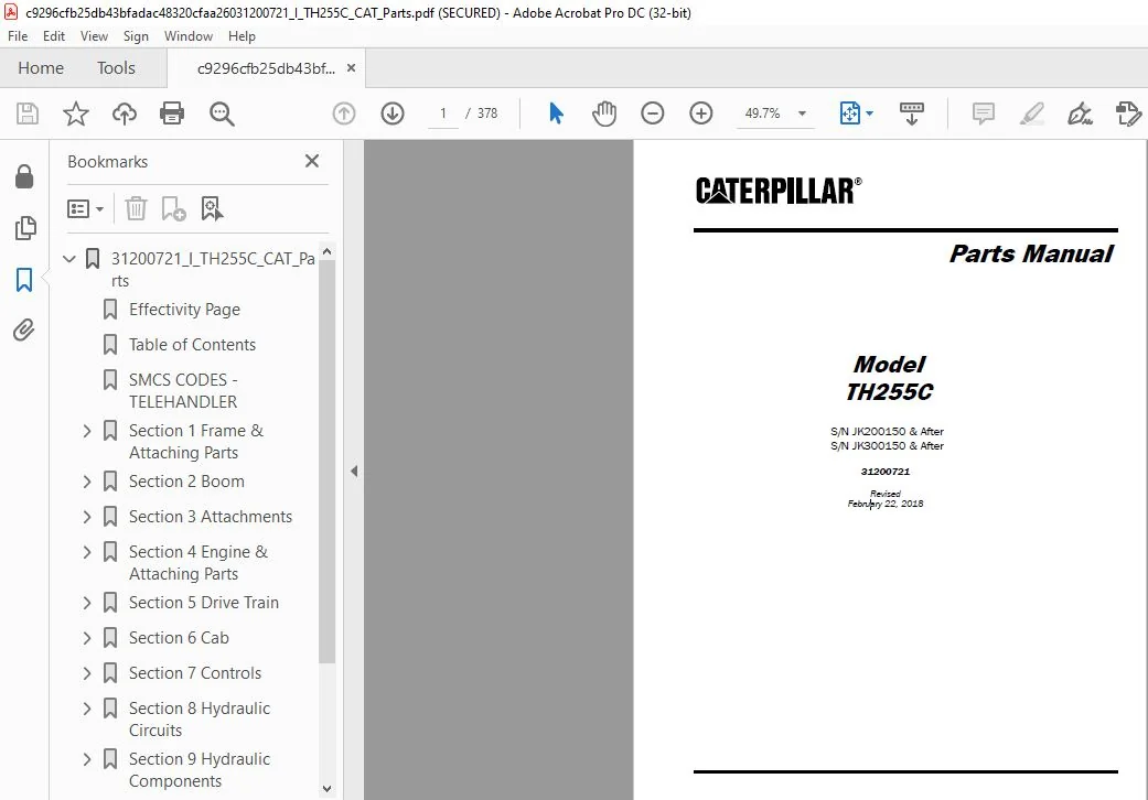
Cat TH255C Telehandler Parts Manual – PDF DOWNLOAD 
Cat TH255C Telehandler Parts Manual – PDF DOWNLOAD
Cat TH255C Telehandler Parts Manual – PDF DOWNLOAD
Original price was: $80.00.$29.95Current price is: $29.95.
Cat TH255C Telehandler Parts Manual – PDF DOWNLOAD
S/N JK200150 & After
S/N JK300150 & After
31200721
Instant PDF Download
Available immediately
Save to Your Device
Download & keep forever
Antivirus Scanned
100% virus-free
Trusted Worldwide
175,000+ customers
Description
Cat TH255C Telehandler Parts Manual – PDF DOWNLOAD
DESCRIPTION:
Cat TH255C Telehandler Parts Manual – PDF DOWNLOAD
Language : English
Pages :378
Downloadable : Yes
File Type : PDF
Size:33 .3
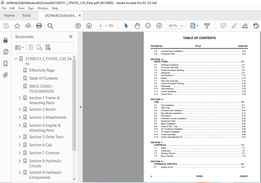
TABLE OF CONTENTS:
Cat TH255C Telehandler Parts Manual – PDF DOWNLOAD
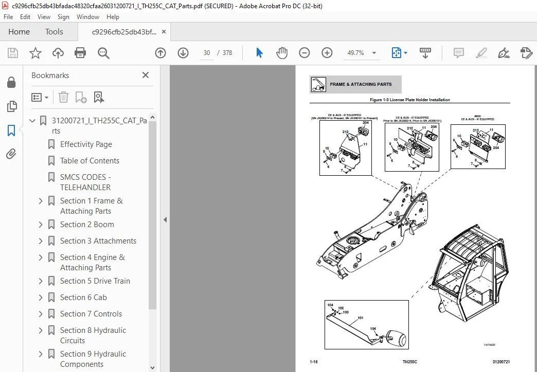
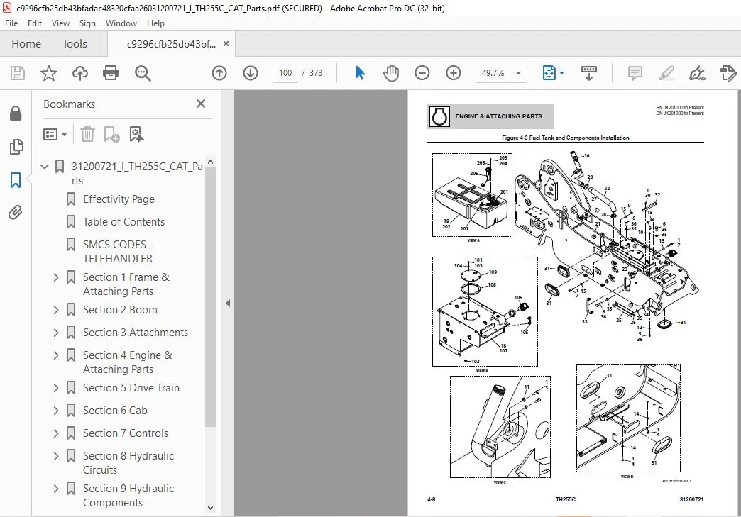
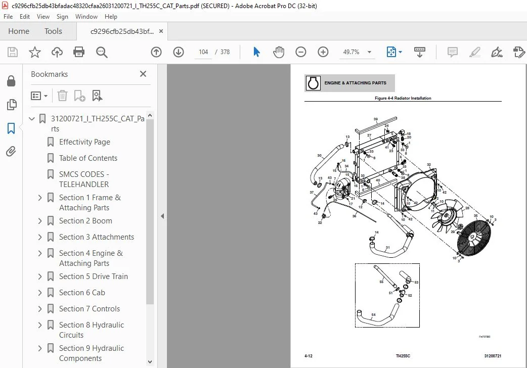
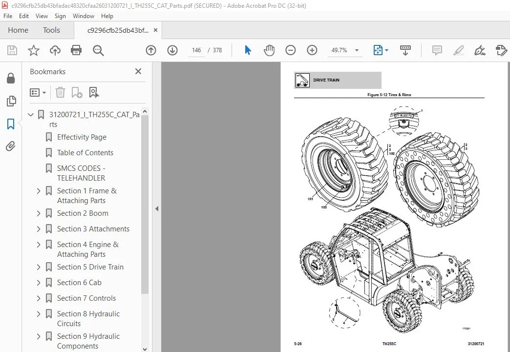
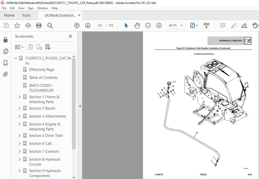
31200721_I_TH255C_CAT_Parts.................................................  1
	Effectivity Page........................................................  3
	Table of Contents.......................................................  5
	SMCS CODES - TELEHANDLER................................................  9
	Section 1 Frame & Attaching Parts....................................... 15
		Figure 1-1 Frame & Attaching Parts.................................. 16
		Figure 1-2 Covers................................................... 22
		Figure 1-3 License Plate Holder Installation........................ 30
		Figure 1-4 Hitches.................................................. 32
		Figure 1-5 Hitch Assembly........................................... 36
		Figure 1-6 Mirror & Bracket Installation............................ 40
	Section 2 Boom.......................................................... 43
		Figure 2-1 Boom Assembly - Components............................... 44
		Figure 2-2 Boom Assembly - Pads & Shims............................. 48
		Figure 2-3 Quick Coupler............................................ 50
		Figure 2-4 Manual Quick Coupler Installation........................ 52
		Figure 2-5 Hydraulic Quick Coupler Installation..................... 54
	Section 3 Attachments................................................... 57
		Figure 3-1 Standard Carriage........................................ 58
		Figure 3-2 Universal Standard Carriage.............................. 60
		Figure 3-3 Side Tilt Carriage....................................... 62
		Figure 3-4 Universal Side Tilt Carriage............................. 64
		Figure 3-5 Universal Side Shift Carriage............................ 66
		Figure 3-6 Forks.................................................... 68
		Figure 3-7 Grapple Bucket........................................... 70
		Figure 3-8 Light Material Buckets................................... 76
		Figure 3-9 Fork Mounted Hook........................................ 78
		Figure 3-10 Universal Hitch Attachment.............................. 80
		Figure 3-11 Universal Quick Attach Lifting Hook..................... 82
		Figure 3-12 Multi-Purpose Bucket.................................... 84
		Figure 3-13 Fork Muck Attachment (w/GRAB)........................... 86
		Figure 3-14 Reflective Plates Installation (Forks).................. 88
		Figure 3-15 Reflective Plates Installation (Bucket) (Italy)......... 90
	Section 4 Engine & Attaching Parts...................................... 93
		Figure 4-1 Engine Installation...................................... 94
		Figure 4-2 Fuel Tank & Lines........................................ 98
		Figure 4-3 Fuel Tank and Components Installation....................100
		Figure 4-4 Radiator Installation....................................104
		Figure 4-5 Air Cleaner Installation.................................108
		Figure 4-6 Exhaust Installation.....................................110
		Figure 4-7 Engine Heater Installation...............................114
		Figure 4-8 Lubricity Doser Installation.............................116
		Figure 4-9 Precleaner Filter........................................118
	Section 5 Drive Train...................................................121
		Figure 5-1 Drivetrain Installation..................................122
		Figure 5-2 Front Axle Assembly......................................124
		Figure 5-3 Central Housing & Steering...............................126
		Figure 5-4 Differential.............................................128
		Figure 5-5 Hub Reduction............................................132
		Figure 5-6 Brakes...................................................134
		Figure 5-7 Rear Axle Assembly.......................................136
		Figure 5-8 Central Housing & Steering...............................138
		Figure 5-9 Differential.............................................140
		Figure 5-10 Hub Reduction...........................................142
		Figure 5-11 Fender Installation.....................................144
		Figure 5-12 Tires & Rims............................................146
	Section 6 Cab...........................................................149
		Figure 6-1 Cab Installation.........................................150
		Figure 6-2 Open Cab.................................................156
		Figure 6-3 Enclosed Cab Installation................................158
		Figure 6-4 Rear Window Installation.................................162
		Figure 6-5 Cab Interior.............................................164
		Figure 6-6 Overhead Console Installation............................168
		Figure 6-7 Suspension Seat..........................................170
		Figure 6-8 Wiper Installation.......................................172
		Figure 6-9 Heater & A/C - Cab.......................................174
		Figure 6-10 AC Condenser Installation...............................182
		Figure 6-11 AC System Installation..................................184
		Figure 6-12 Heater Assembly.........................................186
		Figure 6-13 Heater Assembly with AC.................................188
	Section 7 Controls......................................................191
		Figure 7-1 Brake....................................................192
		Figure 7-2 Accelerator..............................................196
		Figure 7-3 Steering Column..........................................198
		Figure 7-4 Boom Joystick............................................200
	Section 8 Hydraulic Circuits............................................203
		Figure 8-1 Supply Circuit...........................................204
		Figure 8-2 Dump Circuit.............................................208
		Figure 8-3 Steer Select.............................................212
		Figure 8-4 Service/Park Brake.......................................214
		Figure 8-5 Boom Joystick............................................216
		Figure 8-6 Lift Cylinder............................................220
		Figure 8-7 Extend/Retract Cylinder..................................224
		Figure 8-8 Tilt & Compensating......................................226
		Figure 8-9 Auxiliary Hydraulics.....................................228
		Figure 8-10 Rear Auxiliary Hydraulics...............................230
		Figure 8-11 Auxiliary Hydraulics Pressure Relief....................232
		Figure 8-12 Hydraulic Tank Breather Installation....................234
	Section 9 Hydraulic Components..........................................239
		Figure 9-1 Lift Cylinder............................................240
		Figure 9-2 Extend/Retract Cylinder..................................246
		Figure 9-3 Tilt Cylinder............................................250
		Figure 9-4 Compensating Cylinder....................................254
		Figure 9-5 Fork Locking Cylinder....................................258
		Figure 9-6 Side Tilt Carriage Cylinder & Grapple Bucket Cylinder....260
		Figure 9-7 Universal Side Shift Cylinder............................262
		Figure 9-8 Main Control Valve.......................................264
		Figure 9-9 Front Drive Motor........................................266
		Figure 9-10 Hydrostatic Drive Pump..................................268
		Figure 9-11 Gear Pump...............................................270
		Figure 9-12 Divertor Valve..........................................272
		Figure 9-13 Steering Select Valve...................................274
		Figure 9-14 Pilot Select Valve......................................276
		Figure 9-15 Brake Valves............................................278
	Section 10 Electrical...................................................281
		Figure 10-1 Engine Compartment Electrical Installation..............282
		Figure 10-2 Boom and Frame Electrical Installation..................284
		Figure 10-3 Cab Electrical Installation.............................290
		Figure 10-4 Cab Switches............................................292
		Figure 10-5 Work Lights.............................................294
		Figure 10-6 Drive Lights............................................298
		Figure 10-7 Engine Harness..........................................302
		Figure 10-8 Frame Harness...........................................308
		Figure 10-9 Frame Option Harness....................................316
		Figure 10-10 Cab Harness............................................322
		Figure 10-11 Cab Roof Harness.......................................334
		Figure 10-12 Roof Worklight Harness.................................336
		Figure 10-13 Boom Worklight Harness.................................338
		Figure 10-14 Beacon Worklight Harness...............................340
		Figure 10-15 Boom Aux Harness.......................................342
		Figure 10-16 LSI Boom Sensor Harness................................344
		Figure 10-17 Mode Select Harness....................................346
		Figure 10-18 Heater Jumper Harness..................................348
		Figure 10-19 Valve Jumper Harness...................................350
		Figure 10-20 AC Condenser Harness...................................352
	Section 11 Decals.......................................................355
		Figure 11-1 Cab & Frame Decals......................................356
		Figure 11-2 Boom Decals.............................................362
	Maintenance parts list..................................................365
	Part Number Index.......................................................367
CAT TH255C TELEHANDLER PARTS MANUAL – PDF DOWNLOAD:
IMAGES PREVIEW OF THE MANUAL:


PLEASE NOTE:
- This is the same manual used by the DEALERSHIPS to SERVICE your vehicle.
- The manual can be all yours – Once payment is complete, you will be taken to the download page from where you can download the manual. All in 2-5 minutes time!!
- Need any other service / repair / parts manual, please feel free to contact us at heydownloadss @gmail.com. We may surprise you with a nice offer
S.M