Trusted Business
Verified & Licensed
Virus Free Files
100% Safe Downloads
Secure Payment
SSL Protected
Instant Delivery
Available Immediately
Sale!


Cat TL1055C TL1255C Parts Manual – PDFDOWNLOAD 
Cat TL1055C TL1255C Parts Manual – PDFDOWNLOAD
Cat TL1055C TL1255C Parts Manual – PDFDOWNLOAD
Original price was: $80.00.$38.95Current price is: $38.95.
Cat TL1055C TL1255C Parts Manual – PDFDOWNLOAD
SN KDE00150 to Present
SN MDD00150 to Present
SN DHW00150 to Present
SN SXM00150 to Present
31200724
Instant PDF Download
Available immediately
Save to Your Device
Download & keep forever
Antivirus Scanned
100% virus-free
Trusted Worldwide
175,000+ customers
Description
Cat TL1055C TL1255C Parts Manual – PDFDOWNLOAD
FILE DETAILS:
Cat TL1055C TL1255C Parts Manual – PDFDOWNLOAD
Language : English
Pages :460
Downloadable : Yes
File Type : PDF
Size:44.1 MB
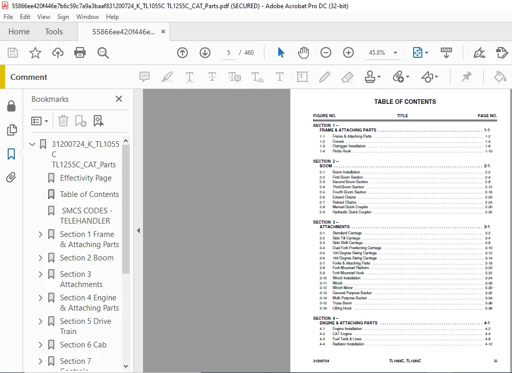
TABLE OF CONTENTS:
Cat TL1055C TL1255C Parts Manual – PDFDOWNLOAD
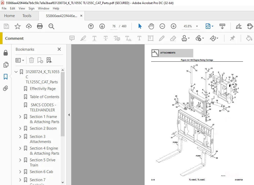
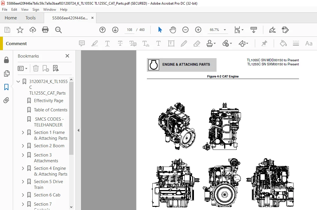
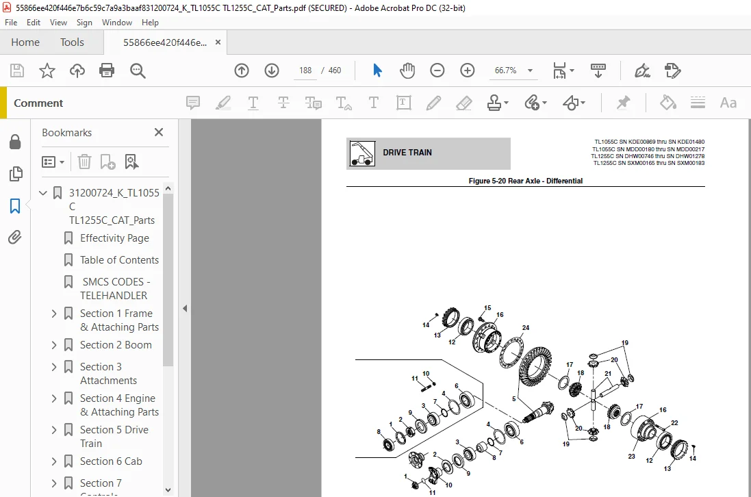
31200724_K_TL1055C TL1255C_CAT_Parts.................................  1
	Effectivity Page.................................................  3
	Table of Contents................................................  5
	 SMCS CODES - TELEHANDLER........................................ 11
	Section 1 Frame & Attaching Parts................................ 17
		Figure 1-1 Frame & Attaching Parts........................... 18
		Figure 1-2 Covers............................................ 20
		Figure 1-3 Outrigger Installation............................ 24
		Figure 1-4 Pintle Hook....................................... 26
	Section 2 Boom................................................... 29
		Figure 2-1 Boom Installation................................. 30
		Figure 2-2 First Boom Section................................ 32
		Figure 2-3 Second Boom Section............................... 36
		Figure 2-4 Third Boom Section................................ 40
		Figure 2-5 Fourth Boom Section............................... 44
		Figure 2-6 Extend Chains..................................... 48
		Figure 2-7 Retract Chains.................................... 52
		Figure 2-8 Manual Quick Coupler.............................. 58
		Figure 2-9 Hydraulic Quick Coupler........................... 60
	Section 3 Attachments............................................ 63
		Figure 3-1 Standard Carriage................................. 64
		Figure 3-2 Side Tilt Carriage................................ 66
		Figure 3-3 Side Shift Carriage............................... 70
		Figure 3-4 Dual Fork Positioning Carriage.................... 72
		Figure 3-5 100 Degree Swing Carriage......................... 74
		Figure 3-6 180 Degree Swing Carriage......................... 76
		Figure 3-7 Forks & Attaching Parts........................... 80
		Figure 3-8 Fork Mounted Platform............................. 82
		Figure 3-9 Fork Mounted Hook................................. 84
		Figure 3-10 Winch Installation............................... 86
		Figure 3-11 Winch............................................ 88
		Figure 3-12 Winch Motor...................................... 92
		Figure 3-13 General Purpose Bucket........................... 94
		Figure 3-14 Multi-Purpose Bucket............................. 96
		Figure 3-15 Truss Boom....................................... 98
		Figure 3-16 Lifting Hook.....................................100
	Section 4 Engine & Attaching Parts...............................103
		Figure 4-1 Engine Installation...............................104
		Figure 4-2 CAT Engine........................................106
		Figure 4-3 Fuel Tank & Lines.................................110
		Figure 4-4 Radiator Installation.............................114
		Figure 4-5 Air Cleaner Installation..........................122
		Figure 4-6 Exhaust Installation..............................124
	Section 5 Drive Train............................................129
		Figure 5-1 Drive Train Components............................130
		Figure 5-2 Front Axle........................................138
		Figure 5-3 Front Axle - Central Housing & Steering...........140
		Figure 5-4 Front Axle - Differential.........................144
		Figure 5-5 Front Axle - Hub Reduction........................148
		Figure 5-6 Front Axle - Brakes...............................154
		Figure 5-7 Front Axle........................................158
		Figure 5-8 Front Axle - Central Housing......................160
		Figure 5-9 Front Axle - Differential.........................162
		Figure 5-10 Front Axle - Hub Reduction.......................164
		Figure 5-11 Front Axle - Brakes..............................166
		Figure 5-12 Front Axle - Steering............................168
		Figure 5-13 Front Axle - Trunion.............................170
		Figure 5-14 Front Axle Differential Assembly.................172
		Figure 5-15 Ring Gear Support Kit............................174
		Figure 5-16 Planet Gear Carrier Kit..........................176
		Figure 5-17 Front Axle Support Assembly......................178
		Figure 5-18 Rear Axle........................................180
		Figure 5-19 Rear Axle - Central Housing & Steering...........182
		Figure 5-20 Rear Axle - Differential.........................186
		Figure 5-21 Rear Axle - Hub Reduction........................190
		Figure 5-22 Rear Axle - Brakes...............................196
		Figure 5-23 Rear Axle........................................200
		Figure 5-24 Rear Axle, Central Housing.......................202
		Figure 5-25 Rear Axle, Differential..........................204
		Figure 5-26 Rear Axle, Hub Reduction.........................206
		Figure 5-27 Rear Axle, Brakes................................208
		Figure 5-28 Rear Axle, Steering..............................210
		Figure 5-29 Rear Axle, Trunion...............................212
		Figure 5-30 Rear, Differential Assembly......................214
		Figure 5-31 Rear Axle, Ring Gear Support Kit.................216
		Figure 5-32 Rear Axle, Planet Gear Carrier Kit...............218
		Figure 5-33 Rear Axle, Support Assembly......................220
		Figure 5-34 Transmission.....................................222
		Figure 5-35 Fender Installation..............................224
		Figure 5-36 Wheel Assembly...................................226
	Section 6 Cab....................................................229
		Figure 6-1 Cab Installation..................................230
		Figure 6-2 Cab Assembly......................................236
		Figure 6-3 Cab Door..........................................240
		Figure 6-4 Cab Interior......................................242
		Figure 6-5 Wipers............................................244
		Figure 6-6 Seats.............................................246
		Figure 6-7 Heater Installation...............................248
		Figure 6-8 Air Conditioning Installation.....................252
	Section 7 Controls...............................................257
		Figure 7-1 Brake.............................................258
		Figure 7-2 Accelerator.......................................260
		Figure 7-3 Steering Column...................................262
		Figure 7-4 Boom Joystick.....................................264
		Figure 7-5 Outrigger & Frame Level/Aux Controllers...........266
	Section 8 Hydraulic Circuits.....................................269
		Figure 8-1 Supply Circuit....................................270
		Figure 8-2 Dump Circuit......................................274
		Figure 8-3 Steer Select Circuit..............................276
		Figure 8-4 Service Brake Circuit.............................278
		Figure 8-5 Boom Joystick Circuit.............................280
		Figure 8-6 Frame Level/Auxiliary Controller..................282
		Figure 8-7 Outrigger Controller..............................284
		Figure 8-8 Lift Cylinder Circuit.............................286
		Figure 8-9 Extend/Retract Cylinder Circuit...................288
		Figure 8-10 Tilt Cylinder & Compensation Cylinder Circuit....290
		Figure 8-11 Boom Hydraulic Assembly..........................292
		Figure 8-12 Auxiliary Hydraulic Circuit......................294
		Figure 8-13 Frame Level Circuit..............................298
		Figure 8-14 Outrigger Circuit................................300
	Section 9 Hydraulic Components...................................303
		Figure 9-1 Lift Cylinder & Hardware..........................304
		Figure 9-2 Extend/Retract Cylinder & Hardware................308
		Figure 9-3 Tilt Cylinder & Hardware..........................310
		Figure 9-4 Compensation Cylinder & Hardware..................312
		Figure 9-5 Frame Level Cylinder & Hardware...................314
		Figure 9-6 Outrigger Cylinder & Hardware.....................316
		Figure 9-7 Stabilizer Cylinder & Hardware....................318
		Figure 9-8 Quick Coupler Cylinder............................320
		Figure 9-9 Swing Carriage & Side Tilt Carriage Cylinder......324
		Figure 9-10 Side Shift Carriage Cylinder.....................328
		Figure 9-11 Dual Fork Positioning Carriage Cylinder..........330
		Figure 9-12 Main Control Valve...............................332
		Figure 9-13 Piston Pump......................................334
		Figure 9-13 Piston Pump......................................338
		Figure 9-14 Hydraulic Tank...................................342
		Figure 9-15 Steer Select Valve...............................344
		Figure 9-16 Brake Valve......................................346
		Figure 9-17 Hydraulic Manifold Valve.........................350
		Figure 9-18 Decompression Valve..............................352
		Figure 9-19 Pressure Reducer Valve...........................354
		Figure 9-20 Divertor Valve...................................356
	Section 10 Electrical............................................359
		Figure 10-1 Engine Compartment Electrical Installation.......360
		Figure 10-2 Arctic Kit.......................................368
		Figure 10-3 Boom & Frame Electrical Installation.............370
		Figure 10-4 Cab Electrical Installation......................374
		Figure 10-5 Cab Switches.....................................376
		Figure 10-6 Work Lights......................................378
		Figure 10-7 Drive Lights.....................................384
		Figure 10-8 Engine Harness...................................386
		Figure 10-9 Transmission Harness.............................394
		Figure 10-10 Frame Harness...................................396
		Figure 10-11 VEC Options Harness.............................404
		Figure 10-12 Transmission Relay Harness......................408
		Figure 10-13 Enclosed Cab Options Harness....................410
		Figure 10-14 Dash Harness....................................412
		Figure 10-15 Instrument Panel Harness........................414
		Figure 10-16 Frame Road Light Harness........................416
		Figure 10-17 Boom Work Light Harness.........................418
		Figure 10-18 Cab Road Light Harness..........................420
		Figure 10-19 Cab Work Light Harness..........................422
		Figure 10-20 A/C Harness.....................................428
		Figure 10-21 VEC Harness.....................................430
		Figure 10-22 Product Link Harness............................432
	Section 11 Decals................................................435
		Figure 11-1 Cab & Frame Decals...............................436
		Figure 11-2 Boom Decals......................................440
	Maintenance Parts List...........................................443
	Part Number Index................................................447
CAT TL1055C TL1255C PARTS MANUAL – PDFDOWNLOAD:
IMAGES PREVIEW OF THE MANUAL:


PLEASE NOTE:
- This is the SAME MANUAL used by the dealerships to diagnose your vehicle
- No waiting for couriers / posts as this is a PDF manual and you can download it within 2 minutes time once you make the payment.
- Your payment is all safe and the delivery of the manual is INSTANT – You will be taken to the DOWNLOAD PAGE.
- So have no hesitations whatsoever and write to us about any queries you may have : heydownloadss @gmail.com
S.M