Trusted Business
Verified & Licensed
Virus Free Files
100% Safe Downloads
Secure Payment
SSL Protected
Instant Delivery
Available Immediately
Sale!


Cat TL642C TL943C Parts Manual – PDF DOWNLOAD 
Cat TL642C TL943C Parts Manual – PDF DOWNLOAD
Cat TL642C TL943C Spare Parts Manual PDF Download
Original price was: $80.00.$39.95Current price is: $39.95.
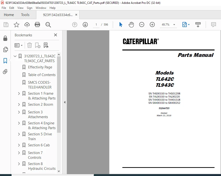
Cat TL642C TL943C Parts Manual – PDF DOWNLOAD
SN THG00150 to THG01208
SN THL00150 to THL00220
SN THH00150 to THH01518
SN SXH00150 to SXH00252
31200723
Instant PDF Download
Available immediately
Save to Your Device
Download & keep forever
Antivirus Scanned
100% virus-free
Trusted Worldwide
175,000+ customers
Description
Cat TL642C TL943C Parts Manual – PDF DOWNLOAD
FILE DETAILS :
Cat TL642C TL943C Parts Manual – PDF DOWNLOAD
Language : English
Pages :596
Downloadable : Yes
File Type : PDF
Size:47.2 MB
TABLE OF CONTENTS:
Cat TL642C TL943C Parts Manual – PDF DOWNLOAD
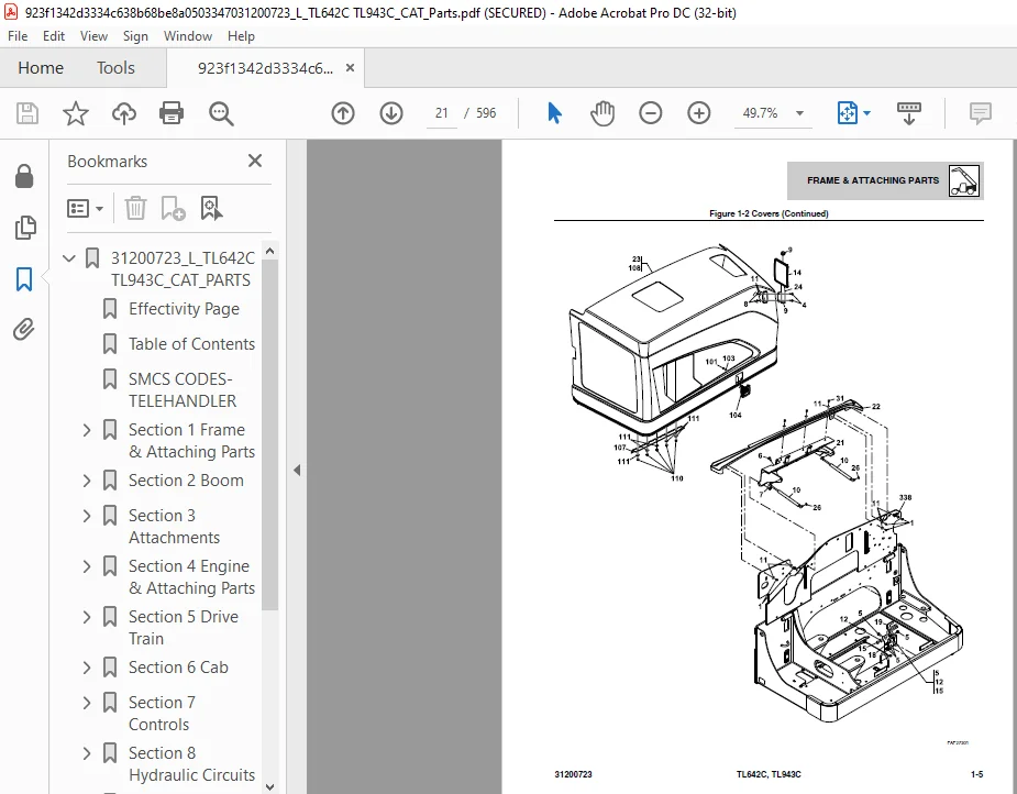
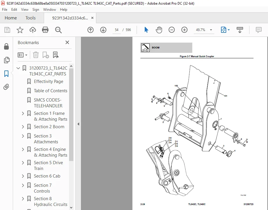
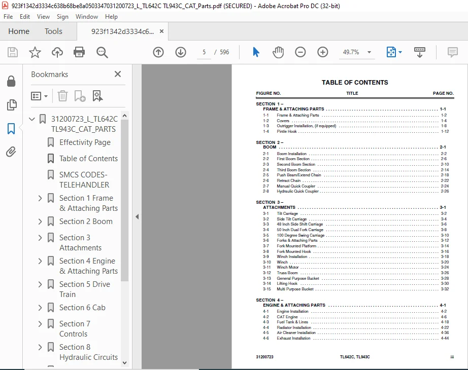
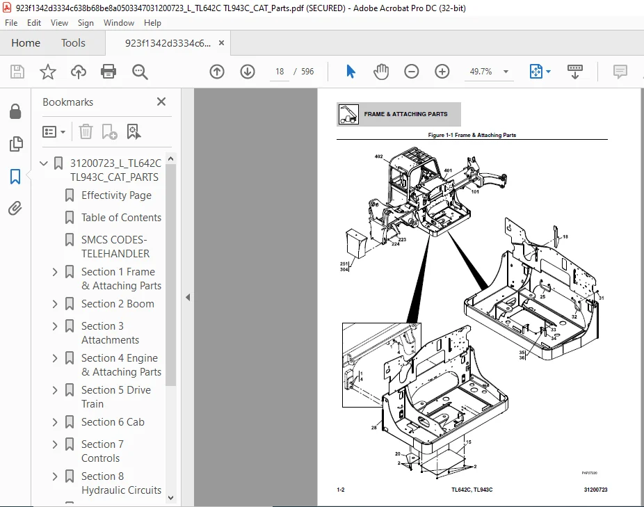
31200723_L_TL642C TL943C_CAT_PARTS..................................  1
	Effectivity Page................................................  3
	Table of Contents...............................................  5
	SMCS CODES- TELEHANDLER......................................... 11
	Section 1 Frame & Attaching Parts............................... 17
		Figure 1-1 Frame & Attaching Parts.......................... 18
		Figure 1-2 Covers........................................... 20
		Figure 1-3 Outrigger Installation, (if equipped)............ 24
		Figure 1-4 Pintle Hook...................................... 28
	Section 2 Boom.................................................. 31
		Figure 2-1 Boom Installation................................ 32
		Figure 2-2 First Boom Section............................... 36
		Figure 2-3 Second Boom Section.............................. 40
		Figure 2-4 Third Boom Section............................... 44
		Figure 2-5 Push Beam/Extend Chain........................... 48
		Figure 2-6 Retract Chain.................................... 52
		Figure 2-7 Manual Quick Coupler............................. 54
		Figure 2-8 Hydraulic Quick Coupler.......................... 56
	Section 3 Attachments........................................... 59
		Figure 3-1 Tilt Carriage.................................... 60
		Figure 3-2 Side Tilt Carriage............................... 62
		Figure 3-3 48 Inch Side Shift Carriage...................... 64
		Figure 3-4 50 Inch Dual Fork Carriage....................... 66
		Figure 3-5 100 Degree Swing Carriage........................ 68
		Figure 3-6 Forks & Attaching Parts.......................... 70
		Figure 3-7 Fork Mounted Platform............................ 72
		Figure 3-8 Fork Mounted Hook................................ 74
		Figure 3-9 Winch Installation............................... 76
		Figure 3-10 Winch........................................... 78
		Figure 3-11 Winch Motor..................................... 82
		Figure 3-12 Truss Boom...................................... 84
		Figure 3-13 General Purpose Bucket.......................... 86
		Figure 3-14 Lifting Hook.................................... 88
		Figure 3-15 Multi Purpose Bucket............................ 90
	Section 4 Engine & Attaching Parts.............................. 95
		Figure 4-1 Engine Installation.............................. 96
		Figure 4-2 CAT Engine.......................................100
		Figure 4-3 Fuel Tank & Lines................................112
		Figure 4-4 Radiator Installation............................116
		Figure 4-5 Air Cleaner Installation.........................130
		Figure 4-6 Exhaust Installation.............................138
		Figure 4-7 Block Heater Installation........................142
	Section 5 Drive Train...........................................145
		Figure 5-1 Drive Train Components...........................146
		Figure 5-2 Front Axle.......................................154
		Figure 5-3 Central Housing & Steering.......................156
		Figure 5-4 Differential.....................................162
		Figure 5-5 Hub Reduction....................................168
		Figure 5-6 Brakes...........................................178
		Figure 5-7 Steering.........................................184
		Figure 5-8 Trunion..........................................186
		Figure 5-9 Differential Kit.................................188
		Figure 5-10 Reduction Bushing...............................190
		Figure 5-11 Planet Gear Carrier Kit.........................192
		Figure 5-12 Steering Case Kit LH............................194
		Figure 5-13 Steering Case Kit RH............................196
		Figure 5-14 Steering Adjust Bolt Kit........................198
		Figure 5-15 Ring Gear Support Kit...........................200
		Figure 5-16 Planet Gear Kit.................................202
		Figure 5-17 Trunion Kit Rear................................204
		Figure 5-18 Trunion Kit Front...............................206
		Figure 5-19 Rear Axle.......................................208
		Figure 5-20 Central Housing & Steering......................210
		Figure 5-21 Differential....................................214
		Figure 5-22 Hub Reduction...................................218
		Figure 5-23 Brakes..........................................226
		Figure 5-24 Rear Axle.......................................230
		Figure 5-25 Central Housing.................................232
		Figure 5-26 Differential....................................236
		Figure 5-27 Hub Reduction...................................240
		Figure 5-28 Brakes..........................................244
		Figure 5-29 Steering........................................248
		Figure 5-30 Rear Axle Trunion...............................252
		Figure 5-31 Rear Axle Differential Assembly.................256
		Figure 5-32 Reduction Bushing...............................260
		Figure 5-33 Planet Gear Carrier Kit.........................262
		Figure 5-34 Ring Gear Support Kit...........................266
		Figure 5-35 Steering Case Kit LH............................270
		Figure 5-36 Steering Case Kit RH............................272
		Figure 5-37 Rear Axle Support Assembly......................274
		Figure 5-38 Transmission....................................276
		Figure 5-39 Fender Installation.............................278
		Figure 5-40 Wheel Assembly..................................280
	Section 6 Cab...................................................283
		Figure 6-1 Cab Assembly.....................................284
		Figure 6-2 Cab..............................................288
		Figure 6-3 Cab Door.........................................292
		Figure 6-4 Cab Interior.....................................294
		Figure 6-5 Wipers...........................................298
		Figure 6-6 Suspension Seat..................................300
		Figure 6-7 Heater Installation..............................302
		Figure 6-8 Air Conditioning Installation....................306
	Section 7 Controls..............................................313
		Figure 7-1 Brake............................................314
		Figure 7-2 Accelerator......................................316
		Figure 7-3 Steering Column..................................318
		Figure 7-4 Boom Joystick....................................320
		Figure 7-5 Outrigger Controller.............................324
		Figure 7-6 Frame Level Controller Installation..............326
		Figure 7-7 Auxiliary Control................................328
	Section 8 Hydraulic Circuits....................................331
		Figure 8-1 Supply Circuit...................................332
		Figure 8-2 Dump Circuit.....................................340
		Figure 8-3 Steer Select Circuit.............................346
		Figure 8-4 Service/Parking..................................348
		Figure 8-5 Boom Joystick Circuit............................352
		Figure 8-6 Outrigger Controller.............................356
		Figure 8-7 Lift Cylinder Circuit............................358
		Figure 8-8 Extend/Retract Cylinder Circuit..................360
		Figure 8-9 Tilt Cylinder & Compensation Cylinder Circuit....362
		Figure 8-10 Auxiliary Hydraulic Circuit.....................366
		Figure 8-11 Frame Level Circuit.............................372
		Figure 8-12 Outrigger Circuit, (if equipped)................374
	Section 9 Hydraulic Components..................................379
		Figure 9-1 Lift Cylinder & Hardware.........................380
		Figure 9-2 Extend/Retract Cylinder & Hardware...............390
		Figure 9-3 Tilt Cylinder & Hardware.........................398
		Figure 9-4 Compensation Cylinder & Hardware.................408
		Figure 9-5 Frame Level Cylinder & Hardware..................418
		Figure 9-6 Outrigger Cylinder & Hardware....................428
		Figure 9-7 Quick Coupler Cylinder...........................432
		Figure 9-8 Side Shift Carriage Cylinder.....................434
		Figure 9-9 Fork Positioning Carriage Cylinder...............436
		Figure 9-10 Swing Carriage Cylinder.........................438
		Figure 9-11 Main Control Valve..............................440
		Figure 9-12 Gear Pump.......................................446
		Figure 9-13 Piston Pump.....................................448
		Figure 9-14 Hydraulic Tank..................................454
		Figure 9-15 Steer Select Valve..............................458
		Figure 9-16 Brake Valve.....................................460
		Figure 9-17 Priority Valve..................................464
		Figure 9-18 Solenoid Valve..................................466
		Figure 9-19 Hydraulic Manifold Valve........................468
		Figure 9-20 Outrigger Valve.................................470
		Figure 9-21 Pressure Reducer Valve, 1360 PSI................474
		Figure 9-22 Divertor Valve..................................476
		Figure 9-23 Side Tilt Carriage Cylinder.....................478
		Figure 9-24 Multi Purpose Bucket Cylinder...................482
	Section 10 Electrical...........................................485
		Figure 10-1 Engine Compartment Electrical Installation......486
		Figure 10-2 Arctic Package Installation.....................494
		Figure 10-3 Boom & Frame Electrical Installation............496
		Figure 10-4 Cab Electrical Installation.....................502
		Figure 10-5 Cab Switches....................................504
		Figure 10-6 Work Lights.....................................506
		Figure 10-7 Drive Lights....................................512
		Figure 10-8 Engine Harness..................................514
		Figure 10-9 Transmission Harness............................522
		Figure 10-10 Frame Harness..................................524
		Figure 10-11 VEC Options Harness............................532
		Figure 10-12 Transmission Relay Harness.....................534
		Figure 10-13 Enclosed Cab Option Harness....................536
		Figure 10-14 Dash Harness...................................538
		Figure 10-15 Instrument Panel Harness.......................540
		Figure 10-16 Frame Road Light Harness.......................542
		Figure 10-17 Boom Work Lights Harness.......................544
		Figure 10-18 Cab Road Light Harness.........................546
		Figure 10-19 Cab Work Light Harness.........................548
		Figure 10-20 A/C Harness....................................554
		Figure 10-21 VEC Harness....................................556
		Figure 10-22 Regen Harness..................................558
		Figure 10-23 Tilt & Aux Control Module......................560
		Figure 10-24 Accessory Module Harness.......................562
		Figure 10-25 Product Link Harness...........................564
	Section 11 Decals...............................................567
		Figure 11-1 Cab & Frame Decals..............................568
		Figure 11-2 Boom Decals.....................................574
	Maintenance Parts List..........................................577
	Part Number Index...............................................581
CAT TL642C TL943C PARTS MANUAL – PDF DOWNLOAD:
IMAGES PREVIEW OF THE MANUAL:


PLEASE NOTE:
- This is the SAME manual used by the dealers to troubleshoot any faults in your vehicle. This can be yours in 2 minutes after the payment is made.
- Contact us at [email protected] should you have any queries before your purchase or that you need any other service / repair / parts operators manual.
S.M