Caterpillar DP135N2 Lift Truck Service Manuals – PDF DOWNLOAD
Original price was: $89.95.$42.95Current price is: $42.95.
Caterpillar DP135N2 Lift Truck Service Manuals – PDF DOWNLOAD
All S/N & Models covered
Description
Caterpillar DP135N2 Lift Truck Service Manuals – PDF DOWNLOAD
DESCRIPTION:
Caterpillar DP135N2 Lift Truck Service Manuals – PDF DOWNLOAD
FOREWORD :
- This service manual describes the specifications, maintenance, and service procedures for 1204F Diesel Engine of Cat Lift Trucks. To maintain the performance of the engine for many years and to ensure safe operation, it is important to use the engine correctly and conduct regular inspection and maintenance, and also to take necessary measures which involves the disassembly, inspection, repair, and assembly of the engine and engine parts.
- Read this manual carefully and understand the work procedures fully before disassembling, inspecting, repairing, or assembling the engine. The contents of this manual are based on the engine model that is being produced at the time of publication. Due to improvements made thereafter, the actual engine that you work on may differ partially from the one described in this manual.
TABLE OF CONTENTS:
Caterpillar DP135N2 Lift Truck Service Manuals – PDF DOWNLOAD
Caterpillar 1204F Diesel Engine Specifications Manual
Specifications Section
Engine Design 4
Fuel Injection Lines 4
Fuel Injection Pump 5
Fuel Injectors 6
Fuel Transfer Pump 6
Fuel Filter Base (Single Secondary Fuel Filter
Base) 7
Fuel Filter Base (Twin Secondary Fuel Filter
Base) 7
Fuel Filter Base (Primary Fuel Filter Base) 8
Fuel Manifold (Rail) 8
Lifter Group 9
Rocker Shaft 9
Valve Mechanism Cover 11
Cylinder Head Valves 11
Cylinder Head 12
Turbocharger (Single Turbocharger) 14
Turbocharger (Series Turbochargers) 16
Exhaust Gas Valve (NRS) 18
Injector (Diesel Exhaust Fluid) 19
Manifold (Diesel Exhaust Fluid) 19
Diesel Exhaust Fluid Tank 20
Diesel Exhaust Fluid Pump 20
Solenoid Valve (DEF Heater Coolant) 21
Exhaust Cooler (NRS) 21
Exhaust Manifold 24
Flexible Exhaust Pipe 25
Camshaft 25
Camshaft Bearings 26
Engine Oil Filter Base 27
Engine Oil Cooler 27
Engine Oil Pump 28
Engine Oil Pressure 28
Engine Oil Pan 29
Crankcase Breather 30
Water Temperature Regulator and Housing 30
Water Pump 31
Cylinder Block 31
Crankshaft 32
Crankshaft Seals 33
Connecting Rod Bearing Journal 34
Main Bearing Journal 34
Connecting Rod 35
Piston and Rings 36
Piston Cooling Jet 37
Balancer 38
Accessory Drive (SAE “B” ) 38
Accessory Drive 39
Front Housing and Covers 39
Gear Group (Front) 40
Flywheel 41
Flywheel Housing 41
Crankshaft Pulley 42
Belt Tensioner 42
Refrigerant Compressor 42
Fan Drive 43
Engine Lifting Bracket 43
Alternator 43
Starter Motor 44
Nitrogen Oxide Sensor 45
Coolant Temperature Sensor 45
Engine Oil Pressure Sensor 46
Boost Pressure Sensor 46
Ammonia Sensor (If equipped) 46
Atmospheric Pressure Sensor 47
Inlet Manifold Temperature Sensor 47
Temperature Sensor (DPF Inlet) 48
Temperature Sensor (DOC Inlet) 48
Temperature Sensor (Exhaust) (Selective
Catalytic Reduction (SCR) Temperature
Sensor) 48
Pressure Sensor (NOx Reduction System)
(Differential Pressure Sensor) 49
Pressure Sensor (NOx Reduction System) 49
Temperature Sensor (NOx Reduction System) 49
Soot Antenna 50
Speed/Timing Sensor 50
Electronic Control Module 51
Glow Plugs 51
Air Compressor (Twin Cylinder Compressor) 52
Air Compressor (Single Cylinder) 53
Index Section
Index 55
Caterpillar 1204F-E44TA & 1204F-E44TTA Industrial Engines Disassembly and Assembly Manual
Disassembly and Assembly Section
Fuel Priming Pump – Remove and Install
(Electric Fuel Lift Pump (EFLP)) 6
Flow Control Valve – Remove and Install 7
Fuel Filter Base – Remove and Install (Twin
Secondary Fuel Filter) 10
Fuel Filter Base – Remove and Install (Single
Secondary Fuel Filter) 13
Water Separator and Fuel Filter (Primary) –
Remove and Install 17
Fuel Manifold (Rail) – Remove and Install 20
Fuel Injection Lines – Remove 22
Fuel Injection Lines – Install 24
Exhaust Cooler (NRS) – Remove and Install (Top
Mounted Turbocharger) 26
Exhaust Cooler (NRS) – Remove and Install
(Side Mounted Turbocharger) 30
Exhaust Cooler (NRS) – Remove and Install
(Twin Turbochargers) 34
Inlet Air Control – Remove (NRS Induction
Mixer) 37
Inlet Air Control – Install (NRS Induction Mixer) 39
Fuel Injection Pump – Remove 42
Fuel Injection Pump – Install 44
Fuel Injection Pump Gear – Remove 46
Fuel Injection Pump Gear – Install 46
Electronic Unit Injector – Remove 47
Electronic Unit Injector – Install 50
Turbocharger – Remove (Second Stage
Turbocharger) 53
Turbocharger – Remove (First Stage
Turbocharger) 55
Turbocharger – Remove (Top Mounted
Turbocharger ) 56
Turbocharger – Remove (Side Mounted
Turbochargers) 57
Turbocharger – Install (Side Mounted
Turbochargers) 59
Turbocharger – Install (Second Stage
Turbocharger) 61
Turbocharger – Install (First Stage
Turbocharger) 63
Turbocharger – Install (Top Mounted
Turbocharger ) 66
Wastegate Solenoid – Remove and Install 68
Exhaust Back Pressure Valve – Remove and
Install 71
Clean Emissions Module – Remove and Install73
Diesel Exhaust Fluid Lines – Remove and
Install 75
Diesel Exhaust Fluid Pump – Remove and
Install 78
DEF Injector and Mounting – Remove and
Install 80
Diesel Exhaust Fluid Tank – Remove and
Install 83
Manifold (DEF Heater) – Remove and Install 85
Solenoid Valve (DEF Heater Coolant) – Remove
and Install 89
Flexible Exhaust Pipe – Remove and Install 90
Exhaust Manifold – Remove and Install (Twin
Turbochargers Exhaust manifold) 94
Exhaust Manifold – Remove and Install (Single
Turbocharger Exhaust Manifold) 97
Exhaust Elbow – Remove and Install 101
Exhaust Elbow – Remove and Install (Top
Mounted and Side Mounted Turbocharger
Exhaust Elbow) 102
Support and Mounting (CEM) – Remove and
Install 103
Inlet and Exhaust Valve Springs – Remove and
Install 105
Inlet and Exhaust Valves – Remove and
Install 109
Engine Oil Filter Base – Remove and Install 112
Engine Oil Cooler – Remove 113
Engine Oil Cooler – Install 114
Engine Oil Pump – Remove 115
Engine Oil Pump – Install 116
Water Pump – Remove 117
Water Pump – Install 118
Water Temperature Regulator – Remove and
Install 120
Flywheel – Remove 121
Flywheel – Install 122
Crankshaft Rear Seal – Remove 123
Crankshaft Rear Seal – Install 124
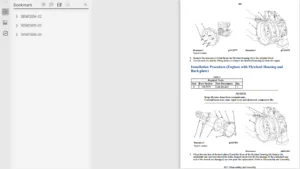
Flywheel Housing – Remove and Install (Wet
Back End Housing) 125
Flywheel Housing – Remove and Install
(Standard Housing) 128
Crankshaft Pulley – Remove and Install 131
Crankshaft Front Seal – Remove and Install 132
Crankshaft Front Seal – Remove and Install
(Crankshaft Front Seal for Heavy Duty Front
Cover) 133
Front Cover – Remove and Install 134
3
Table of Contents
Front Cover – Remove and Install (Heavy Duty
Front Cover) 136
Gear Group (Front) – Remove and Install 137
Gear Group (Front) – Remove and Install (Heavy
Duty Gear Group (Front)) 142
Idler Gear – Remove 151
Idler Gear – Install 153
Housing (Front) – Remove 156
Housing (Front) – Remove (Heavy Duty Housing
(Front)) 158
Housing (Front) – Install 159
Housing (Front) – Install (Heavy Duty Housing
(Front)) 162
Accessory Drive – Remove and Install
(Accessory Drive SAE “B”) 165
Accessory Drive – Remove and Install
(Accessory Drive SAE “A”) 168
Crankcase Breather – Remove 170
Crankcase Breather – Install 171
Valve Mechanism Cover – Remove and
Install 173
Rocker Shaft and Pushrod – Remove 175
Rocker Shaft – Disassemble 177
Rocker Shaft – Assemble 178
Rocker Shaft and Pushrod – Install 179
Cylinder Head – Remove 183
Cylinder Head – Install 187
Lifter Group – Remove and Install (Hydraulic
Lifter Group) 191
Camshaft – Remove and Install 192
Camshaft Gear – Remove and Install 194
Camshaft Bearings – Remove and Install 199
Engine Oil Pan – Remove and Install (Aluminum
and Pressed Steel Oil Pans) 200
Engine Oil Pan – Remove and Install (Cast Iron
Oil Pan) 204
Balancer – Remove 208
Balancer – Install 210
Piston Cooling Jets – Remove and Install 212
Pistons and Connecting Rods – Remove 214
Pistons and Connecting Rods – Disassemble 215
Pistons and Connecting Rods – Assemble 216
Pistons and Connecting Rods – Install 218
Connecting Rod Bearings – Remove (Connecting
Rods in Position) 220
Connecting Rod Bearings – Install (Connecting
Rods in Position) 221
Crankshaft Main Bearings – Remove and Install
(Crankshaft in Position) 222
Crankshaft – Remove 227
Crankshaft – Install 229
Crankshaft Timing Ring – Remove and Install 232
Crankshaft Gear – Remove and Install 233
Crankshaft Gear (Balancer Drive) – Remove and
Install 235
Bearing Clearance – Check 236
Refrigerant Compressor – Remove and
Install 237
Nitrogen Oxide Sensor – Remove and Install
(Nitrogen Oxide Sensor on Engine) 240
Nitrogen Oxide Sensor – Remove and Install
(Nitrogen Oxide Sensor Positioned in Original
Equipment Manufacture Exhaust Tube
Assembly) 242
Atmospheric Pressure Sensor – Remove and
Install 243
Camshaft Position Sensor – Remove and
Install 244
Crankshaft Position Sensor – Remove and
Install 245
Coolant Temperature Sensor – Remove and
Install 246
Engine Oil Pressure Sensor – Remove and
Install 247
Fuel Temperature Sensor – Remove and
Install 248
Ammonia Sensor – Remove and Install
(Ammonia Sensor if Equipped) 249
Soot Antenna – Remove and Install 251
Temperature Sensor (Exhaust) – Remove and
Install (Selective Catalytic Reduction (SCR)
Temperature Sensor) 252
Temperature Sensor (DPF) – Remove and
Install 253
Temperature Sensor (Catalyst Inlet) – Remove
and Install 254
Temperature Sensor (Cooled Exhaust Gas) –
Remove and Install 255
Pressure Sensor (Cooled Exhaust Gas) –
Remove and Install (Differential Pressure
Sensor and Inlet Pressure Sensor) 256
Boost Pressure Sensor – Remove and Install 260
Inlet Manifold Temperature Sensor – Remove
and Install 260
Glow Plugs – Remove and Install 261
Alternator Belt – Remove and Install 263
Idler Pulley – Remove and Install (Grooved Idler
Pulley) 264
Idler Pulley – Remove and Install (Flat Idler
Pulley) 265
Belt Tensioner – Remove and Install 266
Fan – Remove and Install 267
4
Table of Contents
Fan Drive – Remove and Install 268
Electronic Control Module – Remove 268
Electronic Control Module – Install 272
Alternator – Remove 275
Alternator – Install 278
Electric Starting Motor – Remove and Install 281
Air Compressor – Remove and Install (Single
Cylinder Air Compressor) 282
Air Compressor – Remove and Install (Twin
Cylinder Air Compressor) 288
Index Section
Index 296
Caterpillar 1204F Diesel Engine Systems Operation Testing and Adjusting Manual
Systems Operation Section
General Information
Introduction 4
Engine Operation
Basic Engine 9
Air Inlet and Exhaust System (Series
Turbochargers) 12
Air Inlet and Exhaust System (Single
Turbocharger) 18
Clean Emissions Module (Diesel Oxidation
Catalyst (DOC), Diesel Particulate Filter (DPF)
and Selective Catalytic Reduction (SCR)
System) 23
Clean Emissions Module (Diesel Oxidation
Catalyst (DOC) and Selective Catalytic
Reduction (SCR) System) 25
DEF Dosing Control System 28
Cooling System 34
Lubrication System 35
Electrical System 36
Cleanliness of Fuel System Components 38
Fuel Injection 39
Electronic Control System 48
Power Sources 68
Glossary of Electronic Control Terms 73
Testing and Adjusting Section
Fuel System
Fuel System – Inspect 79
Air in Fuel – Test 79
Finding Top Center Position for No 1 Piston 81
Fuel Injection Timing – Check 82
Fuel Quality – Test 83
Fuel System – Prime 83
Gear Group (Front) – Time 84
Air Inlet and Exhaust System
Air Inlet and Exhaust System – Inspect 85
Turbocharger – Inspect (Single Turbocharger) 86
Turbocharger – Inspect (Series
Turbochargers) 89
Exhaust Cooler (NRS) – Test 92
Compression – Test 93
Engine Valve Lash – Inspect 94
Valve Depth – Inspect 95
Valve Guide – Inspect 96
Diesel Exhaust Fluid Quality – Test 97
Aftertreatment SCR System Dosing – Test 98
Diesel Exhaust Fluid Tank – Flush 102
Lubrication System
Engine Oil Pressure – Test 105
Engine Oil Pump – Inspect 105
Excessive Bearing Wear – Inspect 106
Excessive Engine Oil Consumption – Inspect 106
Increased Engine Oil Temperature – Inspect 106
Cooling System
Cooling System – Check 107
Cooling System – Inspect 107
Cooling System – Test 108
Engine Oil Cooler – Inspect 109
Water Temperature Regulator – Test 110
Water Pump – Inspect 110
Basic Engine
Position the Valve Mechanism Before
Maintenance Procedures 111
Piston Ring Groove – Inspect 111
Connecting Rod – Inspect 112
Cylinder Block – Inspect 113
Cylinder Head – Inspect 113
Piston Height – Inspect 114
Flywheel – Inspect 115
Flywheel Housing – Inspect 115
Gear Group – Inspect 117
Crankshaft Pulley – Check 117
Electrical System
Alternator – Test 119
Battery – Test 121
Charging System – Test 121
V-Belt – Test 122
Electric Starting System – Test 123
Index Section
Index 127
Caterpillar 1204F Diesel Engine Troubleshooting Manual
Troubleshooting Section
Introduction
General Information 5
Welding Precaution 6
Electronic Service Tools 7
Electronic System Overview
System Overview 10
Component Location 12
Diesel Particulate Filter Regeneration 22
Engine Monitoring System 22
Diagnostic Capabilities 23
Electrical Connectors 24
Configuration Parameters
Configuration Parameters 29
Diagnostic Trouble Codes
Diagnostic Trouble Codes 32
Event Codes
Event Codes 52
Symptom Troubleshooting
Acceleration Is Poor or Throttle Response Is Poor 64
Alternator Problem (Charging Problem and/or Noisy
Operation) 72
Battery Problem 74
Clean Emissions Module Has High Oxygen Level 75
Coolant Contains Oil 76
Coolant Level Is Low 78
Coolant Temperature Is High 79
Coolant Temperature Is Low 83
Crankcase Breather Ejects Oil 85
Crankcase Fumes Disposal Tube Has Oil Draining 86
Cylinder Is Noisy 89
DEF Concentration Is Incorrect 92
DEF Pressure Does Not Respond 95
DEF Pressure Is High 97
DEF Pressure Is Low 101
DEF Tank Level Is Low 106
DEF Tank Temperature Is High 108
DEF Tank Temperature Is Low 110
Diesel Oxidation Catalyst Has Incorrect Inlet
Temperature 113
Diesel Oxidation Catalyst Has Low Conversion
Efficiency 116
Diesel Particulate Filter Collects Excessive Soot (If
Equipped) 117
Diesel Particulate Filter Temperature Is Low (If
Equipped) 121
Engine Cranks but Does Not Start 123
Engine Does Not Crank 131
Engine Has Early Wear 133
Engine Has Mechanical Noise (Knock) 135
Engine Misfires, Runs Rough or Is Unstable 138
Engine Overspeeds 144
Engine Shutdown Occurrence 147
Engine Shutdown Occurs Intermittently 148
Engine Stalls at Low RPM 150
Engine Top Speed Is Not Obtained 153
Engine Vibration Is Excessive 160
Exhaust Has Excessive Black Smoke 162
Exhaust Has Excessive White Smoke 166
Exhaust System Contains Coolant 171
Exhaust System Contains Oil 172
Exhaust Temperature Is High 174
Fuel Consumption Is Excessive 177
Fuel Contains Water 181
Fuel Rail Pressure Problem 182
Fuel Temperature Is High 193
Inlet Air Is Restricted 196
Intake Manifold Air Pressure Is High 197
Intake Manifold Air Pressure Is Low 198
Intake Manifold Air Temperature Is High 200
NOx Conversion Is Low 203
NRS Exhaust Gas Temperature Is High 209
NRS Mass Flow Rate Problem 211
Oil Consumption Is Excessive 217
Oil Contains Coolant 220
Oil Contains Fuel 222
Oil Level Is Low 224
Oil Pressure Is Low 225
Power Is Intermittently Low or Power Cutout Is
Intermittent 230
SCR Catalyst Has Incorrect Inlet Temperature 237
SCR Warning System Problem 240
Valve Lash Is Excessive 248
Circuit Tests
Aftertreatment Identification Module – Test 250
CAN Data Link – Test 253
Coolant Level – Test 257
Cooling Fan Speed – Test 259
Data Link – Test 261
Data Link Configuration Status – Test 269
DEF Control Module Power – Test 271
DEF Line Heater – Test 275
DEF Pump – Test 280
DEF Pump Pressure Sensor – Test 283
DEF Pump Sensor Supply – Test 285
DEF Tank Sensor – Test 286
Electrical Power Supply – Test 290
Ether Starting Aid – Test 295
Fuel Transfer Pump – Test 299
Glow Plug Starting Aid – Test 305
Idle Validation – Test 310
Indicator Lamp – Test 317
Injector Data Incorrect – Test 319
Injector Solenoid – Test 321
Mode Selection – Test 328
Motorized Valve – Test 331
NOx Sensor – Test 337
Power Take-Off – Test 340
Relay – Test (Aftertreatment Power Relay) 343
Sensor Calibration Required – Test 346
Sensor (Data Link Type) – Test 350
Sensor Signal (Analog, Active) – Test 355
Sensor Signal (Analog, Passive) – Test 361
Sensor Supply – Test 370
Solenoid Valve – Test (Solenoid Valves that Connect
to the Engine ECM) 375
Solenoid Valve – Test (Solenoid Valves that Connect
to the Dosing Control Unit (DCU)) 381
3
Table of Contents
Soot Sensor – Test 387
Speed Control – Test (Analog) 391
Speed Control – Test (PWM) 396
Speed/Timing – Test 403
Switch Circuits – Test (Multiposition Throttle
Switch) 410
Valve Position – Test 413
Water in Fuel – Test 420
Service
Service Tool Features 424
Service Tool Error Identifiers 455
Customer Passwords 468
Factory Passwords 468
ECM Will Not Accept Factory Passwords 469
Electronic Service Tool Does Not Communicate 469
Codes that Inhibit Operation of Aftertreatment
System 474
Test ECM Mode 476
ECM Software – Install 477
ECM – Replace 478
Electrical Connectors – Inspect 479
Injector Code – Calibrate 484
Index Section
Index 486
Caterpillar 1204F-E44TA & 1204F-E44TTA Industrial Engines Operation & Maintenance Manual
Foreword 4
Safety Section
Safety Messages 5
General Hazard Information 8
Burn Prevention 12
Fire Prevention and Explosion Prevention 13
Crushing Prevention and Cutting Prevention 15
Mounting and Dismounting 15
High Pressure Fuel Lines 15
Before Starting Engine 17
Engine Starting 17
Engine Stopping 18
Electrical System 18
Engine Electronics 19
Product Information Section
General Information 20
Product Identification Information 30
Operation Section
Lifting and Storage 33
Features and Controls 39
Engine Diagnostics 57
Engine Starting 63
Engine Operation 66
Cold Weather Operation 68
Engine Stopping 72
Maintenance Section
Refill Capacities 74
Maintenance Recommendations 89
Maintenance Interval Schedule 92
Warranty Section
Warranty Information 130
Reference Information Section
Reference Materials 131
Index Section
Index 134
IMAGES PREVIEW OF THE MANUAL:
CATERPILLAR DP135N2 LIFT TRUCK SERVICE MANUALS – PDF DOWNLOAD:
PLEASE NOTE:
- This is the same manual used by the DEALERSHIPS to SERVICE your vehicle.
- The manual can be all yours – Once payment is complete, you will be taken to the download page from where you can download the manual. All in 2-5 minutes time!!
- Need any other service / repair / parts manual, please feel free to contact us at heydownloadss @gmail.com . We may surprise you with a nice offer
S.V