Caterpillar EP18TCA Lift Trucks Service Manuals – PDF DOWNLOAD
Original price was: $98.95.$29.95Current price is: $29.95.
Caterpillar EP18TCA Lift Trucks Service Manuals – PDF DOWNLOAD
All S/N & Models covered
Description
Caterpillar EP18TCA Lift Trucks Service Manuals – PDF DOWNLOAD
DESCRIPTION:
Caterpillar EP18TCA Lift Trucks Service Manuals – PDF DOWNLOAD
INTRODUCTION :
- Most accident happens due to the disregard of basic safety rules or precautions. In order to prevent accidents from happening, the factors responsible for accidents must be avoided beforehand. For this reason, please read this manual and fully understand the precautions for safety and the proper procedures and directions for inspection and maintenance before starting operation. Performing maintenance and repair without adequate knowledge may cause inadvertent accidents.
- It is not possible to cover all the possible cases of accidents in this “Service manual -Chassis & Mast-“. Therefore, attention should be given to precautions other than the ones mentioned in this “Service manual -Chassis & Mast-“. Especially, when repair and maintenance work which are not covered in this “Service manual -Chassis & Mast-” are carried out, always work under the direction of an instructor who understands the matter.
Using this “Service manual -Chassis & Mast-” :
- This manual has information about the layout and names of main components, procedures for disassembly, assembly, inspection, adjustment, maintenance, and hints for troubleshooting which are in effect mainly for the model EP13TCA~20TCA.
- Since the parts used in this machine are subject to change for the sake of better quality, performance enhancement and safety, some portions of the contents and illustrations of this “Service manual -Chassis & Mast-” may not be identical.
TABLE OF CONTENTS:
Caterpillar EP18TCA Lift Trucks Service Manuals – PDF DOWNLOAD
Caterpillar EP18TCA Chassis & Mast Lift Truck Service Manual
SAFETY WORK 1
1 Precautions for safe inspection and
maintenance work 1
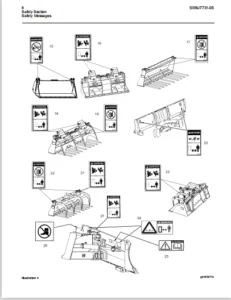
2 Safety labels 5
3 Model name and serial numbers 8
4 Cautions for maintenance 10
5 Tightening torque for bolts 13
6 Maintenance tools and inspection devices 14
7 Data of LOCTITE and THREEBOND products 15
1 GENERAL 16
1-1 Appearance 16
1-2 Specifications 17
2 FRONT AXLE (DRIVE) 19
2-1 Disassembly and reassembly 19
2-1-1 Front axle – removal 19
2-1-2 Disassembly transfer ASS’Y 21
2-1-3 Reassembly the transfer ASS’Y 28
3 REAR AXLE (STEERING) 42
3-1 Disassembly and reassembly 42
3-1-1 Rear axle – removal and installation 42
3-1-2 Rear axle – disassembly and reassembly 43
3-2 Inspection and adjustment 45
3-2-1 Angle sensor comp – adjustment 45
3-2-2 EPS torque sensor – adjustment 45
3-3 Troubleshooting 48
3-3-1 Rear axle – troubleshooting 48
4 TYRE 49
4-1 Front tyre 49
4-1-1 Front tyre – disassembly and reassembly 49
4-1-2 Tyre size (front) 49
4-2 Rear tyre 50
4-2-1 Rear tyre – disassembly and reassembly 50
4-2-2 Tyre size (rear) 50
4-3 Inspection and adjustment 51
4-3-1 Bolt nut – inspection 51
4-3-2 Air pressure – inspection 51
4-3-3 Tyre – visual inspection and replacement 52
4-4 Troubleshooting 52
4-4-1 Tyre – troubleshooting 52
5 STEERING LINKAGE 53
5-1 Disassembly and reassembly 53
5-1-1 Steering linkage- disassembly and reassembly 53
5-2 Inspection and adjustment 56
5-2-1 Joint – inspection and replacement 56
5-2-2 Knob – inspection and replacement 56
5-2-3 Steering wheel – inspection and replacement 56
5-2-4 Chain comp , roller – adjustment 57
6 BRAKE 58
6-1 Foot brake 58
6-1-1 Foot brake – disassembly and reassembly 58
6-2 Parking brake 59
6-2-1 Parking brake – disassembly and reassembly 59
6-3 Inspection and adjustment 60
6-3-1 Brake pedal – adjustment 60
6-3-2 Brake pedal – inspection 61
6-3-3 Microswitch of parking brake lever – adjustment 62
6-3-4 Parking lever – inspection and adjustment 62
6-3-5 Master cylinder ASS’Y- inspection and replacement 63
6-3-6 Master cylinder air bleeding 64
6-4 Troubleshooting 66
6-4-1 Brake – troubleshooting 66
7 HYDRAULIC SYSTEM 68
7-1 Oil piping circuit 68
7a CONROL VALVE AND VALVE LINKAGE 69
7a-1 Disassembly and reassembly 69
7a-1-1 Valve linkage – disassembly and reassembly 69
7a-1-2 Control valve 71
7a-2 Inspection and adjustment 72
7a-2-1 Relief pressure – adjustment 72
7a-2-2 Microswitch – adjustment 73
7a-3 Trouble shooting 74
7a-3-1 Control valve – troubleshooting 74
7b OIL TANK AND OIL PIPING 75
7b-1 Disassembly and reassembly 75
7b-1-1 Oil tank – disassembly and reassembly 75
7b-1-2 Oil piping replacement – precautions 78
7b-2 Inspection and adjustment 79
7b-2-1 Oil – inspection 79
7b-2-2 Recommended oil and quantity for hydraulic circuit
(except brake and gear oil) 79
7b-2-3 Oil tank and filters – cleaning and check 80
7b-3 Troubleshooting 80
7b-3-1 Oil tank – troubleshooting 80
7c HYDRAULIC PUMP 81
7c-1 Removal and installation 81
7c-1-1 Hydraulic pump – removal and installation 81
7d CYLINDER 82
7d-1 Disassembly and reassembly 82
7d-1-1 Lift cylinder – removal : 2SP – mast (2 – stage simplex) 82
7d-1-2 Lift cylinder – removal : 2FP-mast
(2-stage duplex), 3FP-mast (3-stage triplex) 85
7d-1-3 Tilt cylinder – removal 88
7d-1-4 Lift cylinder – installation and adjustment 89
7d-1-5 Tilt cylinder – installation 90
7d-1-6 Lift cylinder – disassembly and reassembly 90
7d-1-7 Tilt cylinder – disassembly and reassembly 101
7d-2 Inspection and adjustment 102
7d-2-1 Cylinder comp – inspection 102
7d-2-2 Piston rod – inspection 102
7d-2-3 Drift for lift and tilt – inspection 103
7d-3 Variation of the tilt cylinder 104
7d-3-1 Tilt angle by masts 104
7d-4 Troubleshooting 105
7d-4-1 Cylinder – troubleshooting 105
8 MAST 106
8-1 Disassembly and reassembly 106
8-1-1 Lift bracket ASS’Y- removal 106
8-1-2 Mast ASS’Y – removal 107
8-1-3 Mast – disassembly and reassembly 109
8-2 Inspection and adjustment 112
8-2-1 Mast, lift bracket and roller shaft – inspection 112
8-2-2 Back shoe – inspection 113
8-2-3 Lift chain – inspection and replacement 113
8-2-4 Chain bolt – inspection 114
8-2-5 Chain wheel – inspection 114
8-2-6 Roller – inspection and replacement 115
8-2-7 Fork – inspection and replacement 115
8-2-8 Lift chain – inspection and adjustment 116
8-2-9 Mast lean- adjustment 117
8-3 Troubleshooting 118
8-3-1 Mast Lift bracket Fork – troubleshooting 118
9 MOTOR 119
9-1 Disassembly and reassembly 119
9-1-1 Traction motor – removal and installation 119
9-1-2 Hydraulic motor – removal and installation 119
9-1-3 EPS motor – removal and installation 121
9-1-4 Traction motor – disassembly and reassembly 122
9-1-5 Hydraulic motor – disassembly and reassembly 123
9-1-6 EPS motor – disassembly and reassembly 124
9-2 Inspection and adjustment 125
9-2-1 Rotor comp (Traction/hydraulic motor)
– inspection and replacement 125
9-2-2 Armature comp (EPS motor)
– inspection and replacement 126
9-2-3 Brush, brush holder and spring (EPS motor)
– inspection and replacement 128
9-2-4 Motor ASS’Y (Traction/Hydraulic motor)
– inspection 130
9-2-5 Motor ASS’Y (EPS motor) – inspection 131
9-2-6 Oil seal and permanent magnet (EPS motor)
inspection and replacement 132
9-2-7 Motor – specification 132
9-3 Troubleshooting 133
9-3-1 Motor – troubleshooting 133
10 ELECTRIC PARTS 134
10-1 Location and name 134
10a CONTROL UNIT 135
10a-1 Location and name 135
10a-2 Disassembly and reassembly 136
10a-2-1 Control unit – removal and installation 136
10a-2-2 EPS controller – removal and installation 138
10a-2-3 Control unit – disassembly and reassembly 139
10a-3 Check and replacement 142
10a-3-1 Main connector – inspection and replacement 142
10a-3-2 Module, FET – inspection and replacement 143
10a-3-3 Capacitor – check and replacement 145
10b ACCELERATOR 146
10b-1 Disassembly and reassembly 146
10b-1-1 Accelerator linkage – removal and installation 146
10b-2 Inspection and adjustment 147
10b-2-1 Potentiometer – adjustment 147
10b-2-2 Accelerator linkage – adjustment 148
10c DISPLAY PANEL AND DIRECTIONAL SWITCH 149
10c-1 Disassembly and reassembly 149
10c-1-1 Display panel
– disassembly and reassembly 149
10c-1-2 Directional switch
– disassembly and reassembly 150
10d BATTERY 152
10d-1 Removal and installation 152
10d-1-1 Battery – removal and installation 152
10d-2 Inspection and adjustment 153
10d-2-1 Battery – inspection and adjustment 153
10d-2-2 Battery – Cleaning 155
10e CHARGER (BUILT – IN) 156
10e-1 Disassembly and reassembly 156
10e-1-1 Charger ASS’Y – disassembly and reassembly 156
10e-1-2 Transformer – disassembly and reassembly 157
10e-1-3 Built-in charger – specification 158
10e-2 Inspection and replacement 159
10e-2-1 Magnetic contactor – inspection 159
10e-2-2 Plug comp and receptacle
– inspection and replacement 159
10e-2-3 Fuse and fuse base – inspection 159
10e-2-4 Transformer – inspection 160
10e-2-5 Diode – inspection 160
10e-3 Inspection After Assembly 161
10e-3-1 Timer – inspection 161
10e-4 Charging procedure 161
10e-4-1 Automatic charge (Daily charge) 161
10e-4-2 Balancing charge 164
10e-4-3 Inspection after charging 165
10e-5 Voltage tap 166
10e-5-1 Power supply voltage – check 166
10e-5-2 Voltage tap – selection 166
10e-5-3 Voltage tap – changing 167
10e-5-4 Fuse (three-phase voltage) – replacement 167
11 LASER POINTER (OPTION) 168
11-1 Adjustment 168
11-1-1 Fork level – adjustment 168
11-1-2 Laser optical axis – adjustment 168
12 SERVICE DATA 169
12-1 Standard work hours 169
Caterpillar EP18TCA Controller Lift Truck Service Manual
1 Adjustment of SICOS-AC 1
1-1 Explanation of the monitor display 1
1-1-1 Indicator panel 1
1-1-2 Indication of display 2
1-1-3 Function of display 3
1-1-4 Various kinds of mode selection 9
1-2 Explanation of control boards 17
1-2-1 Basic control board construction 17
1-2-2 Travel/Hydraulic board 18
1-2-3 EPS controller board 18
1-2-4 Rotary switch on the Travel/Hydraulic board 20
1-2-5 Rotary switch on the EPS conotroller board 21
1-2-6 Adjustment Standards List for EP-TCA series 23
1-2-7 Other settings 24
1- 3 SICOS-AC check and adjustment 26
1-3-1 Chassis insulation check 26
1-3-2 Battery voltage calibration 27
1-3-3 Current sensor check 28
1-3-4 Model setting 31
1-3-5 Hydraulic function setting and adjustment 32
1-3-6 Switch back(plugging/regenerative)
braking force adjustment 35
1-3-7 Regenerative braking force
check and adjustment 36
1-3-8 Display monitor symbol (icon) check and setting 38
1-3-9 Display language check and setting 40
1-3-10 Optional function check and setting 41
1-3-11 Display brightness check and adjustment 43
1-3-12 Hour meter working check 44
1-3-13 Auto power off function working check 44
1-3-14 Battery electrolyte level (optional)
working check 45
1-3-15 Turn signal lamp working check 45
1-3-16 Load sensor (optional) working check
and calibration 46
1-3-17 Cooling fan working check 47
1-3-18 LIft interrupt (optional) working check 48
1-3-19 Accelator potentiometer adjustment 49
1-3-20 Steering angle potentiometer adjustment 51
1-3-21 OIS (Operation Interlock System)
working check 52
1-3-22 Hydraulic oil level warning (optional)
working check 54
1-3-23 Brake oil level warning working check 54
1-3-24 Turning speed reduction (optional)
adjustment and working check 55
1-3-25 Laser positioner (optional) working check 56
1-3-26 Built-in charger (optional) working check 56
2 Troubleshooting 57
2-1 Self diagnosis function 57
2-1-1 Display 57
2-1-2 Error messeages and conditions to appear 59
2-2 Error history memory 61
2-2-1 Error history memory 1 61
2-2-2 Error history memory 2 63
2-2-3 Clearing the error history memory
(memory initialization) 64
2-3 I/O Check 65
2-3-1 Indication of the I/O check mode 65
2-3-2 I/O port table 67
3 Wiring (Diagrams) 69
3-1 Wiring, system 69
3-1-1 [Body] 69
3-1-2 [Fingertip] 70
3-2 Wiring, body 71
3-2-1 [Body] 71
3-2-2 [Fingertip] 72
3-2-3 [3 400V Built-in charger] 73
3-3 Harness, body 74
3-3-1 [Body] 74
3-3-2 [Lead wire chart] 75
3-3-3 [Fingertip] 76
3-4 Controller wiring 77
3-5 Controller harness 78
3-6 Main controller ASS’Y 79
3-7 Wiring, BC 80
3-7-1 [3 200V] 80
3-7-2 [3 400V] 81
3-8 Harness, BC 82
3-8-1 [3 200V] 82
3-8-2 [3 400V] 83
3-9 Wiring, lamp 84
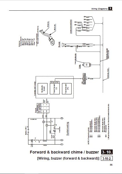
3-10 Forward & backward chime / buzzer 85
3-10-1 [Wiring, chime (forward & backward)] 85
3-10-2 [Wiring, buzzer (forward & backward)] 86
3-10-3 [Wiring, chime (forward)] 87
3-10-4 [Wiring, chime (backward)] 88
3-11 Wiring, lift limit 89
4 Reference 90
4-1 MPU board connectors 90
4-1-1 Pin arrangement of connector housing 90
4-1-2 Name of parts 90
4-1-3 Installation of terminals into housing 91
4-1-4 How to extract terminals 92
4-1-5 Crimp tools 93
4-2 Water resistant connector 94
4-2-1 Water resistant connectors 94
4-2-2 Water resistant connectors
(other than those described above) 94
IMAGES PREVIEW OF THE MANUAL:
CATERPILLAR EP18TCA LIFT TRUCKS SERVICE MANUALS – PDF DOWNLOAD:
PLEASE NOTE:
- This is the same manual used by the dealers to diagnose and troubleshoot your vehicle
- You will be directed to the download page as soon as the purchase is completed. The whole payment and downloading process will take anywhere between 2-5 minutes
- Need any other service / repair / parts manual, please feel free to contact [email protected] . We still have 50,000 manuals unlisted
S.V