Caterpillar GC30K Lift Truck Service Manuals – PDF DOWNLOAD
Original price was: $89.95.$29.95Current price is: $29.95.
Caterpillar GC30K Lift Truck Service Manuals – PDF DOWNLOAD
All S/N & Models covered 500+ Pages
Description
Caterpillar GC30K Lift Truck Service Manuals – PDF DOWNLOAD
DESCRIPTION:
Caterpillar GC30K Lift Truck Service Manuals – PDF DOWNLOAD
FOREWORD :
- This service manual is a guide to servicing of Cat® lift trucks. The instructions are grouped by systems to serve the convenience of your ready reference. Long productive life of your lift trucks depends to a great extent on correct servicing — servicing consistent with what you will learn from this service manual.
- Read the respective sections of this manual carefully and familiarize yourself with all the components you will work on, before attempting to start a test, repair or rebuild job. The descriptions, illustrations and specifications contained in this manual are of the trucks with the serial numbers in effect at the time it was approved for printing. Cat lift truck reserves the right to change specifications or design without notice and without incurring obligation.
SAFETY PRECAUTIONS:
The serviceman or mechanic may be unfamiliar with many of the systems on this truck. This makes it important to use caution when performing service work. A knowledge of the system and/or components is important before the removal or disassembly of any component. Because of the size of some of the truck components, the serviceman or mechanic should check the weights noted in this Manual. Use proper lifting procedures when removing any components. Following is a list of basic precautions that should always be observed.
- Read and understand all warning plates and decals on the truck before operating, lubricating or repairing the product.
- Always wear protective glasses and protective shoes when working around trucks. In particular, wear protective glasses when pounding on any part of the truck or its attachments with a hammer or sledge. Use welders gloves, hood/goggles, apron and other protective clothing appropriate to the welding job being performed. Do not wear loosefitting or torn clothing. Remove all rings from fingers when working on machinery.
- Do not work on any truck that is supported only by lift jacks or a hoist. Always use blocks or jack stands to support the truck before performing any disassembly.
- Lower the forks or other implements to the ground before performing any work on the truck. If this cannot be done, make sure the forks or other implements are blocked correctly to prevent them from dropping unexpectedly.
- Use steps and grab handles (if applicable) when mounting or dismounting a truck. Clean any mud or debris from steps, walkways or work platforms before using. Always face truck when using steps, ladders and walkways. When it is not possible to use the designed access system, provide ladders, scaffolds, or work platforms to perform safe repair operations.
TABLE OF CONTENTS:
Caterpillar GC30K Lift Truck Service Manuals – PDF DOWNLOAD
Caterpillar GC15K Chassis & Mast Service Manual
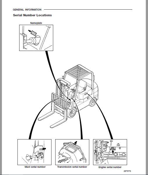
GENERAL INFORMATION
COOLING SYSTEM
ELECTRICAL SYSTEM
POWER TRAIN
POWERSHIFT TRANSMISSION
FRONT AXLE AND
REDUCTION DIFFERENTIAL
REAR AXLE
BRAKE SYSTEM
STEERING SYSTEM
FUEL SYSTEM
HYDRAULIC SYSTEM
MAST AND FORKS
SERVICE DATA
Caterpillar 4G63 Liquefied Petroleum Gas Supplement Service Manual
Types of LP-gas 1
Guideline for selecting LP-gas for lift-truck engines 1
LP-gas knock rating and octane number 2
Adverse effects of olefins on LP-gas fuel system 2
Vapor pressure vs temperature for mixture of propane
and normal butane 2
Structure and Function 4
1 Outline of LP-gas device 4
2 LP-gas device layout 5
3 Main component structures 6
3 1 LP-gas tank 6
3 1 1 Pressure relief valve 6
3 1 2 Fixed liquid level gauge 7
3 1 3 Service valve (LP-gas outlet valve) 7
3 1 4 Fuel level indicator 8
3 2 Filter (Vacuum fuel lock filter) 9
3 3 Hydrostatic relief valve 10
3 4 Converter (vaporizer) and LP-gas carburetor 11
3 4 1 Converter (vaporizer) 11
3 4 2 LP-gas carburetor 11
Actions to be taken in the event of a failure 12
Troubleshooting 14
Disassembly and reassembly 17
1 Main components of LP-gas device (4G63, 4G64) 17
2 Main components of LP-gas device (6G72) 18
3 Disassembly and reassembly of LP-gas carburetor /mixer 19
4 Disassembly and reassembly of converter/regulator (vaporizer) 21
5 Disassembly and reassembly of LP-gas filter, Fuel lock 27
Inspection and adjustment 33
1 LP-gas tank inspection 33
2 Filter inspection 33
3 Converter (vaporizer) inspection and adjustment 34
4 Idle speed adjustment 35
5 Output power adjustment 36
6 Gas leak check procedure 36
i
CARB Tier 1 Emissions Control System (S-15G, 2001-2002 Model Year)
Introduction 37
1 Outline of CARB Tier 1 LP-gas system 38
2 CARB Tier 1 LP-gas layout 39
3 Main Component Illustrations 40
3 1 Electronic Control Units (ECU) (Version 1 & 2) 40
3 2 Electronic Control Unit Illustration 40
3 3 Oxygen Sensor 41
3 4 Pedal Sensor 41
3 5 Engine Block Temperature Sensor 41
3 6 Mixer and Throttle Body Illustration 42
3 7 Three Way Catalytic Convertor 42
3 8 Dash Light Illustration 43
3 9 Exploded view for use with Pneumatic type models 44
3 10 Exploded view for use with cushion type models 45
Systems Operations
1 Explanation of Operation 46
2 Terminology 46
Sub-system Operating Principles
1 Fuel Control 46
2 Fuel Control Operation 48
3 Throttle and Governor 49
4 Throttle and Governor Operation 50
5 Operating Specifications 50
System Adjustments
1 Diagnostic Kit Installation 51
2 Adjustments 51
3 S15G Screen Layout 54
3 1 Adjustment Details 55
3 2 Diagnostic Screen Layout 56
S-15G Troubleshooting
1 Troubleshooting Problem Detail 57
2 Troubleshooting Tree Detail 60
3 Check Engine Light Blink Codes 62
4 System Fault Codes 62
5 Effects of Fault Conditions 63
ii
Vacuum System Diagram and Wiring Schematics
1 Vacuum System Diagram 65
2 S-15G Fuel System Wiring Schematic 66
3 ECU Pin Location and Function 67
Inspection and Adjustment
1 Periodic Inspection Schedule 68
Caterpillar 4G63, 4G64 Fuel System Supplement Service Manual
General
General Information 1
Notes, Cautions, and Warnings 2
Fuel Systems Cautions 2
English and Metric Fasteners 3
Handling Electrostatic Discharge (ESD) Sensitive Parts 3
Glossary of Terms 4
Maintenance
Maintenance 10
V-Belt Systems 10
Serpentine Belt Systems 10
Cooling System 10
Checking the Coolant Level 11
Engine Electrical System Maintenance 11
Engine Crankcase Oil 11
Oil Recommendation 11
Use of Supplemental Additives 12
Synthetic Oils 12
Checking/Filling Engine Oil Level 12
Changing the Engine Oil 13
Fuel System Inspection and Maintenance 13
Propane Fuel System 13
Inspection and Maintenance of the Fuel Storage Cylinder 13
Inspection and Maintenance of the Fuel Filter 13
Low Pressure Regulator Maintenance and Inspection 14
Checking/Draining Oil Build-up in the Low Pressure Regulator 14
Air Fuel Mixer/Throttle Control Device Maintenance and Inspection 15
Exhaust System and Catalytic Converter Inspection and Maintenance 16
Manufacturer’s Recommended Maintenance Intervals 17
LPG Fuel System Operation
Typical LPG Fuel System Schematic 22
Descriptions and Operation of the Fuel Systems 23
Propane Fuel System 23
LPG Fuel Tank 23
Service Line 23
Fuel Filter 23
Electric Lock Off 24
Low Pressure Regulator (LPR) 24
Air Fuel Mixer 25
Drive by Wire 27
Three Way Catalytic Muffler 27
Engine Control Module (ECM) 28
Heated Exhaust Gas Oxygen Sensor 28
Temperature Manifold Absolute Pressure Sensor (TMAP) 30
I
TABLE OF CONTENTS
Page
Engine RPM Sensor 30
Engine Coolant Temperature Sensor (ECT) 30
Closed Loop Control Schematic 31
LPG Fuel System Diagnostics
LPG Fuel System Diagnosis 34
Fuel System Description 34
Diagnostic Aids 34
LPG Fuel System Diagnosis Chart 35
Symptom Diagnosis
Symptom Diagnosis 42
Important Preliminary Checks 42
Intermittent 44
No Start 46
Hard Start 48
Cuts Out, Misses 51
Hesitation 53
Backfire 54
Lack of Power, Sluggishness, or Sponginess 56
Poor Fuel Economy 58
Rough, Unstable, or Incorrect Idle, Stalling 60
Surges, Chugs 62
Wiring Schematics
On-Vehicle Service Wire Harness Repair 64
Connectors and Terminals 64
Micro-Pack 65
Metri-Pack 65
Weather Pack 65
Communication Port C002 71
Oil Pressure Connector C003 71
Heated Oxygen Sensor (HEGO) Connector C004 72
Fuel Trim Valve (FTV) Connector C005 72
TMAP Connector C006 73
Coil Connector C007 73
Magnetic Pickup Connector C008 74
Throttle Connector C009 74
Pressure Trim Valve (PTV) Connector C010 75
Starter Solenoid Connector C011 75
Engine Coolant Temperature Sensor (ECT) 76
Battery Positive Connector C014 77
Battery Positive Connector C015 77
Alternator Connector C016 78
Alternator Connector C017 78
Instrument Panel Connector C018 79
Instrument Panel Connector C019 79
II
TABLE OF CONTENTS
Page
Diagnostic Trouble Codes
Description of ECM Based Diagnostics 82
Diagnostics Overview of the Spectrum Fuel System 83
Malfunction Indicator Lamp (MIL) 83
Diagnostic Trouble Codes (DTC) 83
Diagnostic Communication Error 84
Using a Laptop Computer to Diagnose the System 85
Installing the Diagnostic Software 85
Connecting a Laptop Computer to the System 85
Diagnostic Trouble Codes
Checking Diagnostic Trouble Codes 86
Clearing Diagnostic Trouble Codes 86
Data Stream
Reading Sensor and Actuator Values 87
Graphing and Data Logging 88
Ignition System Testing 89
Disabling Ignition Outputs 89
Throttle Test 90
Diagnostic Communication Error 91
OBD System Check/Malfunction Indicator Lamp 92
Circuit Description 92
OBD System Check Troubleshooting Chart 93
DTC 111-IAT High Voltage 95
DTC 112-IAT Low Voltage 98
DTC 113-IAT Higher Than Expected 1 101
DTC 114-IAT Higher Than Expected 2 103
DTC 115-Oil Pressure Low 105
DTC 121-ECT High Voltage 108
DTC 122-ECT Low Voltage 112
DTC 123-ECT Higher Than Expected 1 115
DTC 124-ECT Higher Than Expected 2 117
DTC 131-MAP High Pressure 119
DTC 132-MAP Low Voltage 122
DTC 134-BP High Pressure 126
DTC 135-BP Low Pressure 128
DTC 142-Crank Sync Noise 133
DTC 143-Never Crank Synched at Start 137
DTC 211-Closed Loop Multiplier High (LPG) 141
DTC 212-HO2S Open/Inactive 144
DTC 224-Closed Loop Multiplier Low (LPG) 147
DTC 243-Adaptive Lean High (LPG) 149
DTC 244-Adaptive Lean Low (LPG) 152
DTC 261-System Voltage Low 155
DTC 262-System Voltage High 158
DTC 511-COP Failure 160
DTC 512-Invalid Interrupt 162
III
TABLE OF CONTENTS
Page
DTC 513-A/D Loss 164
DTC 514-RTI 1 Loss 166
DTC 515-Flash Checksum Invalid 168
DTC 516-Ram Failure 170
DTC 531-External 5 Volt Reference Lower Than Expected 172
DTC 532-External 5 Volt Reference Higher Than Expected 175
DTC 554-Gaseous Fuel Lo Rev Overrun 177
DTC 555-RTI 2 Loss 179
DTC 556-RTI 3 Loss 181
DTC 611-FPP High Voltage 183
DTC 612-FPP Low Voltage 187
DTC 613-FPP Higher Than IVS Limit 191
DTC 614-FPP Lower Than IVS Limit 193
DTC 631-TPS 1 Signal Voltage High 195
DTC 632-TPS 1 Signal Voltage Low 198
DTC 633-TPS 2 Signal Voltage High 201
DTC 634-TPS 2 Signal Voltage Low 204
DTC 635-TPS 1 Higher Than TPS 2 207
DTC 636-TPS 1 Lower Than TPS 2 211
DTC 637-Throttle Unable to Open 215
DTC 638-Throttle Unable to Close 218
DTC 651-Maximum Governor Speed Override 221
DTC 652-Fuel Rev Limit 224
DTC 653-Spark Rev Limit 226
DTC 721-Transmission Over Temperature 228
Fuel System
Repair Instructions
Propane Fuel System Pressure Relief 232
Propane Fuel System Leak Test 232
Propane Fuel Filter Replacement 232
Low Pressure Lock-Off (LPL) Replacement 233
Pressure Trim Valve (PTV) Replacement 234
Low Pressure Regulator (LPR) Replacement 234
Fuel Trim Valve (FTV) Solenoid 235
Temperature Manifold Absolute Pressure (TMAP) 237
Throttle Body Assembly Replacement 237
Mixer Replacement 238
Engine Coolant Temperature Sensor Replacement 238
Coolant Hose Replacement 238
Vapor Hose Replacement 239
Balance Line Hose Replacement 239
PTV Hose Replacement 239
FTV Hose Replacement 239
Engine Control Module Replacement 240
IV
TABLE OF CONTENTS
Page
Heated Exhaust Gas Oxygen Sensor Replacement 240
Three Way Catalytic Converter Muffler Replacement 240
Magnetic Sensor Replacement 241
Timing Wheel Replacement 241
Timing Wheel Replacement Without Special Tool 242
Magnetic Pickup Sensor Air Gap Adjustment 242
V
IMAGES PREVIEW OF THE MANUAL:
CATERPILLAR GC30K LIFT TRUCK SERVICE MANUALS – PDF DOWNLOAD:
PLEASE NOTE:
- This is the SAME exact manual used by your dealers to fix your vehicle.
- The same can be yours in the next 2-3 mins as you will be directed to the download page immediately after paying for the manual.
- Any queries / doubts regarding your purchase, please feel free to contact [email protected]
S.V