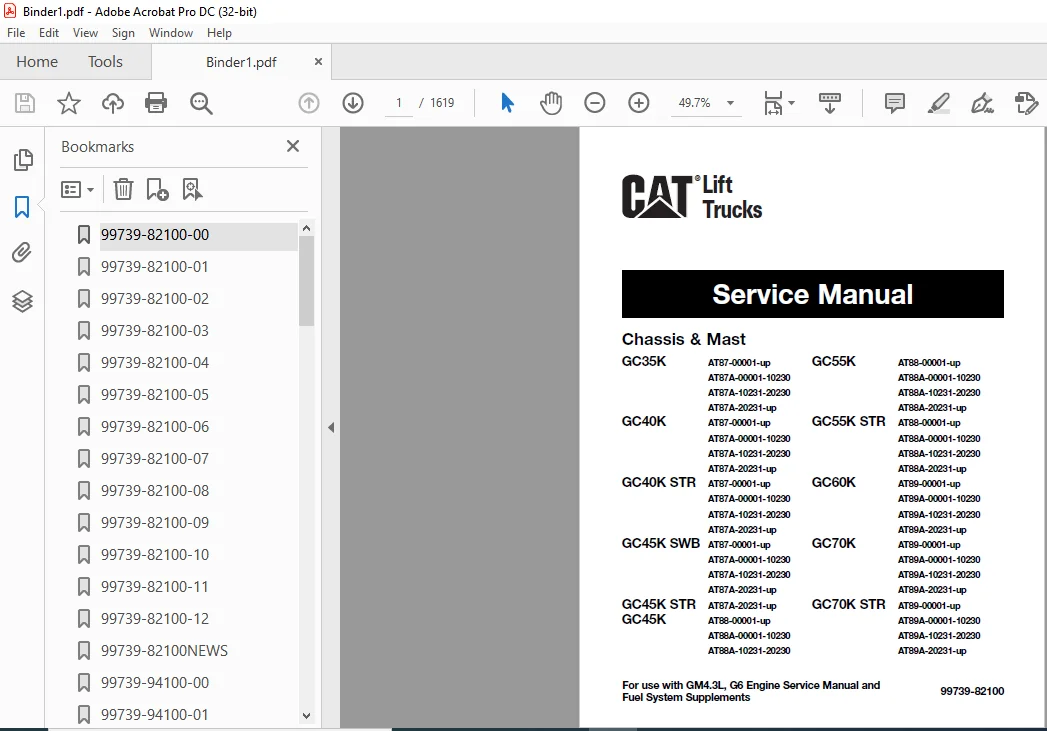
Caterpillar GC45K Lift Truck Service Manuals – PDF DOWNLOAD
Original price was: $89.95.$34.95Current price is: $34.95.
Caterpillar GC45K Lift Truck Service Manuals – PDF DOWNLOAD
Description
Caterpillar GC45K Lift Truck Service Manuals – PDF DOWNLOAD
DESCRIPTION:
Caterpillar GC45K Lift Truck Service Manuals – PDF DOWNLOAD
FOREWORD:
This service manual is a guide to servicing of Cat Lift Trucks for 3.5 thru 7.0 ton models. The instructions are grouped by systems to serve the convenience of your ready reference. Long productive life of your lift trucks depends to a great extent on correct servicing — the servicing consistent with what you will learn from this service manual.
- We hope you read the respective sections of this manual carefully and know all the components you will work on before attempting to start a test, repair or rebuild job.
- The descriptions, illustrations and specifications contained in this manual were of the trucks of serial numbers in effect at the time it was approved for printing. Cat Lift Trucks reserves the right to change specifications or design without notice and without incurring obligation.
The GM4.3 Liter engine’s fuel system was changed to comply with the EPA guidelines in 2004 and again at the beginning of 2007. This manual has minimal information on the fuel systems. Please see the Fuel System Supplement for information regarding the Multi Port Fuel Injection System (MPFI). Also see the engine service manual for general engine repair or rebuild.
For the items pertaining to the engine, refer to the following service manuals:
• GM4.3L (G6) Engine Service Manual
• GM4.3L 2004~2006 Fuel System Supplement
• GM4.3L 2007~2009 Fuel System Supplement
SAFETY PRECAUTIONS:
The serviceman or mechanic may be unfamiliar with many of the systems on this truck. This makes it important to use caution when performing service work. A knowledge of the system and/or components is important before the removal or disassembly of any component. Because of the size of some of the truck components, the serviceman or mechanic should check the weights noted in this Manual. Use proper lifting procedures when removing any components. Following is a list of basic precautions that should always be observed.
- Read and understand all warning plates and decals on the truck before operating, lubricating or repairing the product.
- Always wear protective glasses and protective shoes when working around trucks. In particular, wear protective glasses when pounding on any part of the truck or its attachments with a hammer or sledge. Use welders gloves, hood/goggles, apron and other protective clothing appropriate to the welding job being performed. Do not wear loosefitting or torn clothing. Remove all rings from fingers when working on machinery.
- Do not work on any truck that is supported only by lift jacks or a hoist. Always use blocks or jack stands to support the truck before performing any disassembly.
- Lower the forks or other implements to the ground before performing any work on the truck. If this cannot be done, make sure the forks or other implements are blocked correctly to prevent them from dropping unexpectedly.
- Use steps and grab handles (if applicable) when mounting or dismounting a truck. Clean any mud or debris from steps, walkways or work platforms before using. Always face truck when using steps, ladders and walkways. When it is not possible to use the designed access system, provide ladders, scaffolds, or work platforms to perform safe repair operations.
TABLE OF CONTENTS:
Caterpillar GC45K Lift Truck Service Manuals – PDF DOWNLOAD
Caterpillar GC35K Chassis & Mast Service Manual
GENERALINFORMATION Vehicle Exterior, Models, Serial Number Locations, Dimensions, Technical Data.
COOLING SYSTEM Description, Removal and Installation, Inspection and Adjustment, Fan Belt
Inspection, Fan Belt Adjustment.
ELECTRICAL SYSTEM Description, Disassembly and Re-assembly, Major Electrical Components,
Battery Maintenance, Typical Open Circuit Voltage, Lamp Bulb Specifications,
Electrical System Schematics.
POWER TRAIN Specifications, Structure, Reduction Ratio, Procedures and Key Points for
Removal and Installation.
POWERSHIFT TRANSMISSION 1-Speed Transmission (GC35K-GC55K STR), Specifications, Structure,
Removal and Installation, Torque Converter, Transmission, Control Valve,
Adjustment, Automatic 2-speed Transmission (GC60K-GC70K STR),
Specifications, Structure, Transmission, Solenoid Valve, Adjustment,
Troubleshooting, Service Data.
FRONT AXLE Specifications, Structure, Procedures and Key Points for Removal and
Installation, Axle Shaft and Hub, Reduction Differential, Troubleshooting,
Service Data.
REAR AXLE Specifications, Structure, Procedures and Key Points for Removal and
Installation, Rear Axle Assembly, Steering Cylinder, Adjustment,
Troubleshooting, Service Data.
BRAKE SYSTEM Specifications, Structure, Master Cylinder, Wheel Cylinder, Wheel Brake,
Parking Brake Lever, Adjustment and Tests, Troubleshooting, Service Data.
STEERING SYSTEM Specifications, Structure, Procedures and Key Points for Removal and
Installation, Steering Control Valve, Troubleshooting, Service Data.
HYDRAULIC SYSTEM Specifications, Description, Removal and Installation, Disassembly and
Re-assembly, Inspection and Adjustment, Hydraulic Circuit Diagram,
Troubleshooting, Service Data.
MASTS AND FORKS Specifications, Description, Disassembly and Re-assembly, Inspection and
Adjustment,Troubleshooting, Service Data.
SERVICE DATA Inspection Standards, Periodic Replacement of Parts, Special Tool Table.
Caterpillar GC35K Options Supplement Service Manual
REAR COMBINATION LAMP KIT ………………………………………………… 1
WARNING LAMP KIT …………………………………………………………………… 2
WORKING LAMP KIT ………………………………………………………………….. 4
CREEP SPEED KIT ……………………………………………………………………… 6
FOOT DIRECTIONAL CONTROL GROUP ………………………………….. 8
ENGINE SHUTDOWN KIT (LPG models only) ……………………………. 10
ENCLOSED ALTERNATOR FIELD KIT ………………………………………… 12
DISCONNECT SWITCH KIT ………………………………………………………… 13
UL FUEL CAP KIT (Gasoline models only) …………………………………. 16
KEY KIT ……………………………………………………………………………………….. 17
BACK BUZZER KIT ……………………………………………………………………… 18
DUAL ELEMENT AIR CLEANER …………………………………………………. 19
DUST AND FOUNDRY KIT ………………………………………………………….. 20
1. Precleaner Kit …………………………………………………………………………… 20
2. Gear Pump Seal Kit …………………………………………………………………… 21
3. Magnetic Plug Kit ……………………………………………………………………… 22
4. Dust-Proof Breather Kit ……………………………………………………………… 22
BACK MIRROR KIT ……………………………………………………………………… 23
Caterpillar GM 4.3L (G6) Fuel System Supplement Service Manual
General
Notes, Cautions, and Warnings 2
Fuel Systems Cautions 2
English and Metric Fasteners 3
Handling Electrostatic Discharge (ESD) Sensitive Parts 3
Glossary of Terms 4
Maintenance
Maintenance 10
V-Belt Systems 10
Serpentine Belt Systems 10
Cooling System 10
Checking the Coolant Level 11
Engine Electrical System Maintenance 11
Engine Crankcase Oil 11
Oil Recommendation 11
Use of Supplemental Additives 12
Synthetic Oils 12
Checking/Filling Engine Oil Level 12
Changing the Engine Oil 12
Fuel System Inspection and Maintenance 13
Propane Fuel System 13
Inspection and Maintenance of the Fuel Storage Cylinder 13
Inspection and Maintenance of the Fuel Filter 13
Low Pressure Regulator Maintenance and Inspection 14
Checking/Draining Oil Build-up in the Low Pressure Regulator 14
Air Fuel Mixer/Throttle Control Device Maintenance and Inspection 15
Exhaust System and Catalytic Converter Inspection and Maintenance 16
Gasoline Fuel System 16
Fuel Tank Maintenance and Inspection 16
Gasoline Fuel Filter Inspection and Replacement 16
Fuel Pump Maintenance and Inspection 17
Fuel Pressure Regulator Maintenance and Inspection 17
Fuel Rails and Injectors 17
Fuel Additives 18
Certified Engine Maintenance Intervals 19
LPG Fuel System Operation
Typical LPG Fuel System Schematic 22
Descriptions and Operation of the Fuel Systems 23
Propane Fuel System 23
LPG Fuel Tank 23
Service Line 23
Fuel Filter 23
Electric Lock Off 24
Low Pressure Regulator (LPR) 24
Air Fuel Mixer 25
Drive by Wire 26
I
TABLE OF CONTENTS
Page
Three Way Catalytic Muffler 27
Engine Control Module (ECM) 28
Heated Exhaust Gas Oxygen Sensor 28
Propane Closed Loop Control Schematic 29
Gasoline Fuel System Operation
Gasoline Multi-Port Fuel Injection System Schematic 32
Gasoline Multi-Port Fuel Injection System (MPFI) 33
Gasoline Fuel Storage Tank 33
Gasoline Fuel Pump 33
Fuel Filter 33
Fuel Rail and Pressure Regulator 33
Fuel Injector 33
Drive by Wire 34
Three Way Catalytic Muffler 34
Engine Control Module (ECM) 34
Heated Exhaust Gas Oxygen Sensor 35
Closed Loop Control Schematic 36
LPG Fuel System Diagnostics
LPG Fuel System Diagnosis 38
Fuel System Description 38
Diagnostic Aids 38
Tools 32
Tools Required 32
Duty Cycle Monitoring Tool 38
Diagnostic Scan Tool 38
Pressure Gauges 38
Test Description 38
LPG Fuel System Diagnostic Chart 39
Gasoline Fuel System Diagnostics
Gasoline Fuel System Diagnosis 46
Fuel System Description 46
Diagnostic Aids 46
Test Description – Diagnostic Chart 46
Gasoline Fuel System Diagnostic Chart 48
Symptom Diagnosis
LPG Symptom Diagnosis 54
Important Preliminary Checks 54
Intermittent 55
No Start 56
Hard Start 58
Cuts Out, Misses 60
Hesitation 61
Backfire 62
Lack of Power, Sluggishness, or Sponginess 63
Poor Fuel Economy 64
II
TABLE OF CONTENTS
Page
Rough, Unstable, or Incorrect Idle, Stalling 65
Surges, Chugs 67
Gasoline Symptom Diagnosis 68
Important Preliminary Checks 68
Intermittent 69
No Start 70
Hard Start 72
Cuts Out, Misses 74
Hesitation 75
Backfire 76
Lack of Power, Sluggishness, or Sponginess 77
Poor Fuel Economy 78
Rough, Unstable, or Incorrect Idle, Stalling 79
Restricted Exhaust System Diagnosis 81
Exhaust System Diagnosis 81
Check at heated Exhaust Gas Oxygen Sensor (HEGO) 81
Schematics
On-Vehicle Service Wire Harness Repair 84
Connectors and Terminals 84
Micro-Pack 85
Metri-Pack 85
To Remove a Terminal 85
Weather Pack 85
4 3L Main Wire Harness 88
4 3L LPG Jump Harness 90
4 3L Gasoline Jump Harness 92
4 3L Dual Fuel Jump Harness 94
ECM Connector C001 96
Communication Port C002 97
Injector Connector C003 98
Injector Connector C004 99
Oil Pressure Connector C005 100
Crank Sensor Connector C006 101
Module Connector C007 102
Coil Connector C008 103
Throttle Connector C009 104
EGO Sensor Connector C010 105
TMAP Connector C011 106
CAM Connector C012 107
ECT Connector C013 108
Starter Solenoid Connector C014 109
Battery Connector C015 110
Alternator Connector C016 111
Alternator Connector C017 112
Instrument Panel Connector C018 113
Instrument Panel Connector C019 114
III
TABLE OF CONTENTS
Page
Instrument Panel Connector C020 115
Fuel Lockoff C021 116
Fuel Trim Valve Connector C022 117
Pressure Trim Valve Connector C023 118
Injector 1 Connector C024 119
Injector 2 Connector C025 120
Injector 3 Connector C026 121
Injector 4 Connector C027 122
Injector 5 Connector C028 123
Injector 6 Connector C029 124
Diagnostic Trouble Codes
Description of ECM Based Diagnostics 128
Diagnostics Overview of the Fuel System 129
Malfunction Indicator Lamp (MIL) 129
Spectrum Diagnostic Trouble Codes (DTC) 129
Using a Laptop Computer to Diagnose the System 130
Installing the Diagnostic Software 130
Diagnostic Trouble Codes 131
Checking Diagnostic Trouble Codes 131
Clearing Diagnostic Trouble Codes 131
Data Stream 132
Reading Sensor and Actuator Values 132
Graphing and Data Logging 133
Ignition System Testing 134
Disabling Ignition Outputs 134
Injector Test 135
Disabling Injectors 135
Throttle Test 136
Using a Diagnostic jumper to Diagnose the ECI System 136
Diagnostic Procedures for Dual-Fuel Applications 137
Injection Driver Diagram 137
OBD System Check/Malfunction Indicator Lamp 138
Circuit Description 138
OBD System Check Troubleshooting Chart 139
DTC 111-IAT High Voltage (Bosch® TMAP) 140
Conditions for Setting the DTC 140
Circuit Descriptions 140
DTC 111-IAT Voltage High (Bosch® TMAP) Troubleshooting Chart 141
DTC 112-IAT Low Voltage (Bosch® TMAP) 144
DTC 112-IAT Voltage Low (Bosch® TMAP) Troubleshooting Chart 145
DTC 113-IAT Higher Than Expected 1 (Bosch® TMAP) 146
DTC 114-IAT Higher Than Expected 2 (Bosch® TMAP) 148
DTC 115-Oil Pressure Low 150
DTC 115-Oil Pressure Low Troubleshooting Chart 151
DTC 121-ECT High Voltage 154
DTC 121-ECT High Voltage Troubleshooting Chart 155
IV
TABLE OF CONTENTS
Page
DTC 122-ECT Low Voltage 158
DTC 122-ECT Low Voltage Troubleshooting Chart 159
DTC 123-ECT Higher Than Expected 1 160
DTC 123-ECT Higher Than Expected 1Troubleshooting Chart 161
DTC 124-ECT Higher Than Expected 2 162
DTC 124-ECT Higher Than Expected 2 Troubleshooting Chart 163
DTC 131-MAP High Pressure (Bosch® TMAP) 164
DTC 131-MAP High Pressure (Bosch® TMAP) Troubleshooting Chart 165
DTC 132-MAP Low Voltage (Bosch® TMAP) 168
DTC 132-MAP Low Voltage (Bosch® TMAP) 169
DTC 134-BP High Pressure (Bosch® TMAP) 172
DTC 134-BP High Pressure (Bosch® TMAP) Troubleshooting Chart 173
DTC 135-BP Low Pressure (Bosch® TMAP) 174
DTC 135-BP Low Pressure (Bosch® TMAP) 175
DTC 142-Crank Sync Noise 178
DTC 142-Crank Sync Noise Troubleshooting Chart 179
DTC 143-Never Crank Synched at Start 182
DTC 143-Never Crank Synched at Start Troubleshooting Chart 183
DTC 144-Camshaft Sensor Loss 186
DTC 144-Camshaft Sensor Loss Troubleshooting Chart 187
DTC 145-Camshaft Sensor Noise 190
DTC 145-Camshaft Sensor Noise Troubleshooting Chart 191
DTC 211-Closed Loop Multiplier High (LPG) 194
DTC 211-Closed Loop Multiplier High (LPG) Troubleshooting Chart 195
DTC 212-HO2S Open/Inactive 196
DTC 212-HO2S Open/Inactive Troubleshooting Chart 197
DTC 221-Closed Loop Multiplier High (Gasoline) 200
DTC 221-Closed Loop Multiplier High (Gasoline) Troubleshooting Chart 201
DTC 222-Closed Loop Multiplier Low (Gasoline) 202
DTC 222-Closed Loop Multiplier Low (Gasoline) Troubleshooting Chart 203
DTC 224-Closed Loop Multiplier Low (LPG) 204
DTC 224-Closed Loop Multiplier Low (LPG) Troubleshooting Chart 205
DTC 241- Adaptive Lean Fault (high limit-gasoline) 206
DTC 241- Adaptive Lean Fault (high limit-gasoline) Troubleshooting Chart 207
DTC 242-Adaptive Rich Fault (low limit-gasoline) 210
DTC 242-Adaptive Rich Fault (low limit-gasoline) Troubleshooting Chart 211
DTC 243-Adaptive Lean High (LPG) 212
DTC 243-Adaptive Lean High (LPG) Troubleshooting Chart 213
DTC 244-Adaptive Lean Low (LPG) 214
DTC 244-Adaptive Lean Low (LPG) Troubleshooting Chart 215
DTC 261-System Voltage Low 216
DTC 261-System Voltage Low Troubleshooting Chart 217
DTC 262-System Voltage High 218
DTC 262-System Voltage High Troubleshooting Chart 219
DTC 511-COP Failure 220
DTC 511-COP Failure Troubleshooting Chart 221
DTC 512-Invalid Interrupt 222
V
TABLE OF CONTENTS
Page
DTC 512-Invalid Interrupt Troubleshooting Chart 223
DTC 513-A/D Loss 224
DTC 513-A/D Loss Troubleshooting Chart 225
DTC 514-RTI 1 Loss 226
DTC 514-RTI 1 Loss Troubleshooting Chart 227
DTC 515-Flash Checksum Invalid 228
DTC 515-Flash Checksum Invalid Troubleshooting Chart 229
DTC 516-Ram Failure 230
DTC 516-Ram Failure Troubleshooting Chart 231
DTC 531-External 5 Volt Reference Lower Than Expected 232
DTC 531-External 5 Volt Reference Lower Than Expected Troubleshooting Chart 233
DTC 532-External 5 Volt Reference Higher Than Expected 234
DTC 532-External 5 Volt Reference Higher Than Expected Troubleshooting Chart 235
DTC 555-RTI 2 Loss 236
DTC 555-RTI 2 Loss Troubleshooting Chart 237
DTC 556-RTI 3 Loss 238
DTC 556-RTI 3 Loss Troubleshooting Chart 239
DTC 611-FPP High Voltage 240
DTC 611-FPP High Voltage Troubleshooting Chart 241
DTC 612-FPP Low Voltage 244
DTC 612-FPP Low Voltage Troubleshooting Chart 245
DTC 613-FPP Higher Than IVS Limit 248
DTC 613-FPP Higher Than IVS Limit Troubleshooting Chart 249
DTC 614-FPP Lower Than IVS Limit 250
DTC 614-FPP Lower Than IVS Limit Troubleshooting Chart 251
DTC 631-TPS 1 Signal Voltage High 252
DTC 631-TPS 1 Signal Voltage High Troubleshooting Chart 253
DTC 632-TPS 1 Signal Voltage Low 256
DTC 632-TPS 1 Signal Voltage Low Troubleshooting Chart 257
DTC 633-TPS 2 Signal Voltage High 258
DTC 633-TPS 2 Signal Voltage High Troubleshooting Chart 259
DTC 634-TPS 2 Signal Voltage Low 262
DTC 634-TPS 2 Signal Voltage Low Troubleshooting Chart 263
DTC 635-TPS 1 Higher Than TPS 2 266
DTC 635-TPS 1 Higher Than TPS 2 Troubleshooting Chart 267
DTC 636-TPS 1 Lower Than TPS 2 270
DTC 636-TPS 1 Lower Than TPS 2 Troubleshooting Chart 271
DTC 637-Throttle Unable to Open 274
DTC 637-Throttle Unable to Open Troubleshooting Chart 275
DTC 638-Throttle Unable to Close 278
DTC 638-Throttle Unable to Close Troubleshooting Chart 279
DTC 651-Maximum Governor Speed Override 282
DTC 651-Maximum Governor Speed Override Troubleshooting Chart 283
DTC 652-Fuel Rev Limit 284
DTC 652-Fuel Rev Limit Troubleshooting Chart 285
DTC 653-Spark Rev Limit 286
DTC 653-Spark Rev Limit Troubleshooting Chart 287
DTC 721-Transmission Over Temperature 288
VI
TABLE OF CONTENTS
Page
Fuel System
Repair Instructions 292
Propane Fuel System Pressure Relief 292
Propane Fuel System Leak Test 292
Propane Fuel Filter Replacement 292
Low Pressure Lock-Off (LPL) Replacement 293
Pressure Trim Valve (PTV) Replacement 294
Low Pressure Regulator (LPR) Replacement 294
Fuel Trim Valve (FTV) Solenoid 295
Temperature Manifold Absolute Pressure (TMAP) 295
Electronic Throttle Control Assembly Replacement 296
Mixer Replacement 296
FTV Adapter Replacement 297
Coolant Hose Replacement 297
Vapor Hose Replacement 298
Balance Line Hose Replacement 298
PTV Hose Replacement 298
FTV Hose Replacement 298
Engine Control Module Replacement 299
Heated Exhaust Gas Oxygen Sensor Replacement 299
Three Way Catalytic Converter Muffler Replacement 299
Gasoline Repair Instructions
Gasoline MPFI Fuel System Pressure Relief 299
Gasoline Fuel System Leak Test 300
Electronic Throttle Control Assembly Replacement 300
Fuel Rail Replacement Procedure 301
Injector Replacement 301
Temperature Manifold Absolute Pressure Replacement 302
Heated Exhaust Gas Oxygen Sensor Replacement 302
Caterpillar GM 4.3L, G6 Gasoline Engine Service Manual
Forward I
How to Read This Manual II
Precautions VI
Precautions for Disassembly and Assembly VI
General Precautions VIII
Determining When to Overhaul the Engine 1
Engine Replacement 2
Removal Procedure 2
Installation Procedure 2
Specifications 6
Engine Specifications – Gas and LP 6
General Specifications 8
Major Nuts and Bolts Tightening Torque 11
Sealers, Adhesives, and Lubricants 13
Use of RTV and Anaerobic Sealer (Gasket Eliminator) 14
Diagnostic Information and Procedures 16
Base Engine Misfire Diagnosis 16
Engine Compression Test 17
Engine Noise Diagnosis 18
Valve Train Diagnosis (General) 19
Valve Train Diagnosis (Noise Diagnosis) 19
Engine Mechanical 22
Oil Consumption Diagnosis 22
Low or No Oil Pressure Diagnosis and Testing 22
Oil Leak Diagnosis 22
Repairing the Leak 23
Engine Lubrication 25
Intake Manifold 29
Intake Manifold Removal 30
Intake Manifold Installation 31
Exhaust Manifold 33
Oil Level Indicator and Tube Removal 34
Exhaust Manifold and Heat Shields Removal 34
Exhaust Manifold Clean and Inspect 34
Exhaust Manifold and Heat Shields Installation 35
Oil Level Indicator and Tube Installation 35
Cylinder Head and Valves 37
Valve Rocker Arm Cover Removal (Left) 38
Valve Rocker Arm Cover Removal (Right) 38
Valve Rocker Arm and Push Rod Removal 39
Valve Lifter Removal 41
Valve Stem Oil Seal and Valve Spring Removal 42
Cylinder Head Removal 43
Cylinder Head Disassembly and Assembly 45
Cylinder Head Clean and Inspect 46
Valve Guide Reaming/Valve and Seat Grinding 48
Valve Stem Oil Seal and Valve Spring Installation 49
Valve Lifter Installation 50
Cylinder Head Installation 51
Valve Rocker Arm and Push Rod Installation 53
Valve Rocker Arm Cover Left Installation 54
Valve Rocker Arm Cover Right Installation 55
-XITABLE
OF CONTENTS
Oil Pan, Pump and Filter 57
Oil Pan Removal 58
Oil Pump Removal 59
Oil Filter Adapter Removal 60
Oil Pump Disassembly 60
Oil Pump Assemble 62
Oil Filter Adapter Installation 63
Oil Pump Installation 64
Oil Pan Installation 65
Front Cover, Timing Chain, and Crankshaft Balancer 67
Engine Front Cover Removal 68
Engine Front Cover Oil Seal Removal 68
Timing Chain and Sprockets Removal 68
Crankshaft Balancer Removal 70
Crankshaft Balancer Installation 71
Timing Chain and Sprockets Installation 72
Engine Front Cover Oil Seal Installation 73
Engine Front Cover Installation 73
Balancer and Camshaft 77
Balance Shaft Removal 78
Camshaft Removal 80
Camshaft Bearing Removal 80
Camshaft and Bearings Clean and Inspect 82
Camshaft Bearing Installation 83
Camshaft Installation 84
Balance Shaft and Bearing Clean and Inspect 85
Balance Shaft Installation 86
Crankshaft, Flywheel, Rear Seal, and Bearings 89
Engine Flywheel Removal 90
Crankshaft Rear Oil Seal and Housing Removal 90
Crankshaft and Bearings Removal 91
Crankshaft and Bearings Clean and Inspect 91
Service Prior to Assembly 94
Crankshaft and Bearings Installation 94
Bearing Clearance Measuring Procedures 95
Micrometer Method for Crankshaft Bearings 95
Crankshaft Rear Oil Seal and Housing Installation 103
Engine Flywheel Installation 105
Cylinder Block 107
Engine Block Plug Removal 108
Cylinder Block Clean and Inspect 110
Cylinder Boring and Honing 111
Reboring the Cylinders 112
Cylinder Block Plug Installation 113
Piston and Connecting Rod 117
Piston, Connecting Rod, and Bearing Removal 118
Piston and Connecting Rod Disassembly 119
Piston and Connecting Rod and Bearings Clean and Inspect 119
Piston Selection 122
Piston, Connecting Rod and Bearing Installation 123
Piston and Connecting Rod Assembly 124
Gasoline Carburetor 127
Carburetor Assembly (Upper) 129
Carburetor Assembly (Lower) 131
Carburetor Disassembly 132
Air Horn Disassembly 132
-XIITABLE
OF CONTENTS
Carburetor Inspection 137
Carburetor Assembly 138
Air Horn Assembly 140
Carburetor Adjustment 144
Operational Adjustments 147
Carburetor Installation 148
Electrical Throttle and Governor Control System 149
System Operation 149
ECU Input/Output Interfaces 150
ECU Schematic 151
Method of Operation 152
Speed Control 152
GM 4 3L, G6 Engine ECU Error Code Description 154
Ignition System and Distributor 157
Ignition System – Distributor 158
Distributor Removal 159
Distributor Disassembly 159
Distributor Assembly 159
Coil Removal 160
Coil Installation and Testing 160
Ignition Sensing Coil Testing 160
Distributor Installation 161
Ignition Timing 163
Spark Plug Inspection 163
Alternator and V-Belt (Units built before 01/01/2004) 165
Alternator 167
Accessory Drive Belt Replacement 168
Starter Motor 169
Starter Motor Testing 170
Troubleshooting 170
Fuel System – Gasoline (Units built before 01/01/2004) 173
Fuel Pump and Fuel Hose (Units built before 01/01/2004) 175
Fuel Pump Disassembly and Reassembly (Units built before 01/01/2004) 177
Inspection 178
Main Point of Reassembly 178
Fuel System – LP (Units built before 01/01/2004) 179
Maintenance Checks 180
Vacuum Fuel Lockoff Filter 181
Model J Regulator 182
Pressure Regulator / Converter Service Procedures 182
On-Truck Pressure Test 183
Regulator / Converter Disassembly, Inspection, Cleaning, and Assembly 183
Regulator / Converter Bench Test 183
Pressure / Converter Regulator Installation Tips 183
Regulator/Lockout – Removal 183
Impco CA 100 Air Fuel Mixer 184
LPG Carburetor Adjustment Procedure-co/exhaust Analyzer 187
Governor Speed Adjustment Procedure 187
Accelerator Cable Adjustment – LPG 188
Special Tools and Equipment 189
Caterpillar GM 4.3L, G6 Engine LPG Fuel System Supplement Service Manual
1 — GENERAL INFORMATION
GLOSSARY 1-1
INTRODUCTION 1-9
HOW TO IDENTIFY THE ENGINE YEAR 1-9
SERVICING YOUR EMISSIONS CERTIFIED ENGINE 1-9
FUEL QUALITY 1-9
FUEL SYSTEM CAUTIONS 1-10
WARNINGS, CAUTIONS AND NOTES 1-10
PROPER USE OF THIS SERVICE MANUAL, TOOLS AND EQUIPMENT 1-11
2 — MAINTENANCE
SERPENTINE BELT SYSTEM 2-1
COOLING SYSTEM 2-1
COOLANT 2-2
ENGINE ELECTRICAL SYSTEM MAINTENANCE 2-2
ENGINE CRANKCASE OIL 2-3
FUEL SYSTEM INSPECTION AND MAINTENANCE 2-4
ELECTRONIC PRESSURE REGULATOR (EPR) MAINTENANCE AND INSPECTION 2-6
AIR FUEL MIXER/THROTTLE CONTROL DEVICE MAINTENANCE AND INSPECTION 2-7
EXHAUST SYSTEM AND CATALYTIC CONVERTER INSPECTION AND MAINTENANCE 2-8
3 — LPG FUEL SYSTEM
DESCRIPTION AND OPERATION OF THE FUEL SYSTEMS 3-2
4 — LPG SYSTEM DIAGNOSIS
FUEL SYSTEM DESCRIPTION 4-1
DIAGNOSTIC AIDS 4-1
5 — LPG SYMPTOM DIAGNOSTICS
LPG SYMPTOM DIAGNOSTICS 5-1
INTERMITTENT 5-2
NO START 5-3
HARD START 5-5
CUTS OUT, MISSES 5-7
HESITATION, SAG, STUMBLE 5-8
BACKFIRE 5-9
LACK OF POWER, SLUGGISHNESS, OR SPONGINESS 5-10
POOR FUEL ECONOMY 5-11
ROUGH, UNSTABLE, OR INCORRECT IDLE, STALLING 5-12
SURGES/CHUGGLES 5-14
CRANKCASE VENTILATION SYSTEM INSPECTION/DIAGNOSIS RESULTS OF INCORRECT OPERATION 5-15
6 — DIAGNOSTIC SCAN TOOL
CONTENTS 6-1
DST INSTALLATION INSTRUCTIONS 6-1
INSTALLING THE USB ADAPTER DRIVER 6-7
INSTALLING THE USB ADAPTER DRIVER 6-15
PASSWORD LOGIN 6-17
PASSWORD DIALOG BOX FUNCTIONS 6-18
CONNECTING THE PC TO THE SPECTRUM FUEL SYSTEM 6-20
DST SERVICE PAGES 6-21
SPARK KILL 6-24
INJECTOR KILL 6-24
DBW TEST MODE 6-24
EXTERNAL POWER TEST 6-24
ii
TABLE OF CONTENTS
PLOT/LOG MENU FUNCTIONS 6-25
DST PLOT INTERFACE FUNCTIONS 6-31
SNAPSHOT HOT KEY FUNCTIONS 6-32
DST LOGGER 6-33
REPROGRAMMING THE ECM 6-34
MALFUNCTION INDICATOR LAMP (MIL) 6-37
SPECTRUM DIAGNOSTIC TROUBLE CODES (DTC) 6-37
DLC COMMUNICATION ERROR 6-37
BLINK CODE FUNCTION 6-38
INTERMITTENT PROBLEMS 6-40
7 — ENGINE WIRING SCHEMATIC
CHASSIS SCHEMATIC 7-1
ENGINE SCHEMATIC 7-3
ELECTRICAL FLOW DIAGRAM 7-5
ECM POWER, POWER RELAY CONTROLS & ECM GROUND CIRCUITS PAGE ECM-1 7-7
ECM ENGINE / FUEL SENSOR CIRCUITS (1) PAGE ECM-2 7-8
ECM ENGINE / FUEL SENSOR CIRCUITS (2) PAGE ECM-3 7-9
ECM ACTUATOR CIRCUITS PAGE ECM-4 7-10
ECM INTERFACE CONNECTOR CIRCUITS PAGE ECM-5 7-11
ECM EPR AND DIAGNOSTIC CONNECTOR CIRCUITS PAGE ECM-6 7-12
8 — ENGINE WIRE HARNESS REPAIR
ON-VEHICLE SERVICE WIRE HARNESS REPAIR 8-1
CONNECTORS AND TERMINALS 8-1
MICRO-PACK 8-2
METRI-PACK 8-2
WEATHER-PACK 8-2
9 — DIAGNOSTIC TROUBLE CODES (DTCs)
OBD SYSTEM CHECK/MIL (MALFUNCTION INDICATOR LAMP) 9-1
IGNITION CONTROL SYSTEM DIAGNOSTIC CHART 9-2
DTC-16 — NEVER CRANK SYNCED AT START 9-6
DTC-107 — MAP LOW VOLTAGE 9-10
DTC-108 — MAP HIGH PRESSURE 9-14
DTC-111 — IAT HIGHER THAN EXPECTED 1 9-18
DTC-112 — IAT LOW VOLTAGE 9-20
DTC-113 — IAT HIGH VOLTAGE 9-24
DTC-117 — ECT/CHT LOW VOLTAGE 9-28
DTC-118 — ECT/CHT HIGH VOLTAGE 9-30
DTC-121 — TPS 1 LOWER THAN TPS 2 9-34
DTC-122 — TPS 1 SIGNAL VOLTAGE LOW 9-38
DTC-123 — TPS 1 SIGNAL VOLTAGE HIGH 9-42
DTC-127 — IAT HIGHER THAN EXPECTED 2 9-45
DTC-129 — BP LOW PRESSURE 9-46
DTC-134 — EGO 1 PRE CAT OPEN/LAZY 9-50
DTC-154 — EGO 2 POST CAT OPEN/LAZY 9-54
DTC-187 — FT VOLTAGE LOW 9-58
DTC-188 — FT VOLTAGE HIGH 9-60
DTC-219 — MAX GOVERN SPEED OVERRIDE 9-64
DTC-221 — TPS 1 HIGHER THAN TPS 2 9-66
DTC-222 — TPS 2 SIGNAL VOLTAGE LOW 9-70
DTC-223 — TPS 2 SIGNAL VOLTAGE HIGH 9-74
DTC-336 — CRANK SYNC NOISE 9-78
DTC-337 — CRANK LOSS 9-82
DTC-341 — CAMSHAFT SYNC NOISE 9-86
DTC-342 — CAMSHAFT SENSOR LOSS 9-90
DTC-359 — FUEL RUN-OUT LONGER THAN EXPECTED 9-94
TABLE OF CONTENTS
iii
DTC-524 — OIL PRESSURE LOW 9-96
DTC-562 — SYSTEM VOLTAGE LOW 9-100
DTC-563 — SYSTEM VOLTAGE HIGH 9-102
DTC-601 — FLASH CHECKSUM INVALID 9-104
DTC-604 — RAM FAILURE 9-106
DTC-606 — COP FAILURE 9-108
DTC-642 — EXTERNAL 5 VOLT REFERENCE LOW 9-110
DTC-643 — EXTERNAL 5 VOLT REFERENCE HIGH 9-114
DTC-650 — MIL CONTROL OPEN 9-116
DTC-652 — EXTERNAL 5 VOLT 2 REFERENCE LOW 9-120
DTC-653 — EXTERNAL 5 VOLT 2 REFERENCE HIGH 9-124
DTC-685 — RELAY COIL OPEN 9-126
DTC-686 — RELAY CONTROL GROUND SHORT 9-130
DTC-687 — RELAY COIL SHORT TO POWER 9-132
DTC-1111 — FUEL REV LIMIT 9-136
DTC-1112 — SPARK REV LIMIT 9-138
DTC-1121 — FPP 1 AND 2 REDUNDANCY LOST 9-140
DTC-1151 — CLOSED LOOP MULTIPLIER HIGH LPG 9-142
DTC-1152 — CLOSED LOOP MULTIPLIER LOW LPG 9-146
DTC-1161 — ADAPTIVE LEARN HIGH LPG 9-148
DTC-1162 — ADAPTIVE LEARN LOW LPG 9-152
DTC-1171 — EPR PRESSURE HIGHER THAN EXPECTED 9-154
DTC-1172 — EPR PRESSURE LOWER THAN EXPECTED 9-156
DTC-1173 — EPR COMMUNICATION LOST 9-158
DTC-1174 — EPR SUPPLY VOLTAGE HIGH 9-162
DTC-1175 — EPR SUPPLY VOLTAGE LOW 9-164
DTC-1176 — EPR INTERNAL ACTUATOR FAULT 9-168
DTC-1177 — EPR INTERNAL CIRCUITRY FAULT 9-170
DTC-1178 — EPR INTERNAL COMMUNICATION ERROR 9-172
DTC-1511 — AUX ANALOG PU1 HIGH 9-174
DTC-1512 — AUX ANALOG PU1 LOW 9-178
DTC-1521 — CHT HIGHER THAN EXPECTED 1 9-182
DTC-1522 — CHT HIGHER THAN EXPECTED 2 9-184
DTC-1612 — RTI 1 LOSS 9-186
DTC-1613 — RTI 2 LOSS 9-188
DTC-1614 — RTI 3 LOSS 9-190
DTC-1615 — A/D LOSS 9-192
DTC-1616 — INVALID INTERRUPT 9-194
DTC-1626 — CAN TX FAILURE 9-196
DTC-1627 — CAN RX FAILURE 9-200
DTC-1628 — CAN ADDRESS CONFLICT 9-204
DTC-1645 — MIL CONTROL GROUND SHORT TO POWER 9-206
DTC-2111 — UNABLE TO REACH LOWER TPS 9-210
DTC-2112 — UNABLE TO REACH HIGHER TPS 9-214
DTC-2121 — FPP 1 LOWER THAN FPP 2 9-218
DTC-2122 — FPP 1 HIGH VOLTAGE 9-222
DTC-2123 — FPP 1 LOW VOLTAGE 9-226
DTC-2126 — FPP 1 HIGHER THAN FPP 2 9-230
DTC-2127 — FPP 2 LOW VOLTAGE 9-234
DTC-2128 — FPP 2 HIGH VOLTAGE 9-238
DTC-2229 — BP HIGH PRESSURE 9-242
DTC-2300 — PRIMARY LOOP OPEN/LOW SIDE SHORT TO GROUND 9-244
DTC-2301 — PRIMARY COIL SHORTED 9-248
10 — SERVICING THE FUEL SYSTEM
ENGINE CONTROL MODULE 10-1
ENGINE WIRE HARNESS REPLACEMENT 10-2
FUEL TEMPERATURE (FT) SENSOR REPLACEMENT 10-2
iv
TABLE OF CONTENTS
OIL PRESSURE SENDER 10-3
DISTRIBUTOR 10-3
TEMPERATURE MANIFOLD PRESSURE SENSOR (TMAP) 10-5
FT150 FUEL MIXER 10-6
VACUUM LINE 10-8
ENGINE COOLANT TEMPERATURE SENSOR (ECT) 10-8
HEATED EXHAUST GAS OXYGEN SENSOR (HEGO) 10-9
PROPANE FUEL SYSTEM PRESSURE RELIEF 10-10
FUEL MIXER 10-10
ELECTRONIC PRESSURE REGULATOR (EPR) 10-11
ELECTRONIC PRESSURE REGULATOR (EPR)—SERVICE 10-14
MIXER TO THROTTLE BODY O-RING REPLACEMENT 10-18
MIXER TO THROTTLE PLASTIC THROTTLE BODY SLEEVE REPLACEMENT 10-18
THROTTLE BODY REPLACEMENT 10-19
THROTTLE BODY-ADAPTER O-RING REPLACEMENT 10-19
REPLACEMENT OF ADAPTER-INTAKE MANIFOLD GASKETS 10-20
FUEL VAPOR HOSE—(EPR) TO FUEL MIXER 10-20
SHUT-OFF VALVE REPLACEMENT 10-21
EPR MOUNTING BRACKET 10-22
ECM MOUNTING BRACKET 10-22
LPG FUEL SYSTEM PRESSURE CHECK 10-22
LPG FUEL CONTROL SYSTEM CHECK 10-22
PROPANE FUEL SYSTEM LEAK TEST 10-23
RESTRICTED EXHAUST SYSTEM DIAGNOSIS 10-23
CATALYTIC CONVERTER 10-23
EPR COOLANT HOSE REPLACEMENT 10-24
11 — LPG PARTS DIAGRAM
MIXER AND THROTTLE BODY ASSEMBLY (NEW) 11-1
MIXER AND THROTTLE BODY ASSEMBLY (FORMER) 11-2
EPR ASSEMBLY 11-4
REGULATOR REPAIR 11-6
HOSE ASSEMBLIES COOLANT/VACUUM/FUEL 11-7
ENGINE CONTROL MODULE 11-8
SENSORS 11-9
EXHAUST SYSTEM 11-10
SERVICE TOOLS 11-11
12 — APPENDIX
ALTITUDE VS BAROMETRIC PRESSURE 12-1
IGNITION SYSTEM SPECIFICATIONS 12-1
EXTENDED ECT TEMPERATURE VS RESISTANCE 12-
IMAGES PREVIEW OF THE MANUAL:
CATERPILLAR GC45K LIFT TRUCK SERVICE MANUALS – PDF DOWNLOAD:
PLEASE NOTE:
- This is the SAME exact manual used by your dealers to fix your vehicle.
- The same can be yours in the next 2-3 mins as you will be directed to the download page immediately after paying for the manual.
- Any queries / doubts regarding your purchase, please feel free to contact [email protected]
S.V