Caterpillar Lift Truck DP50N1 Service Manuals – Complete Set – PDF DOWNLOAD
$32.95
Caterpillar Lift Truck DP50N1 Service Manuals – Complete Set – PDF DOWNLOAD
All S/N & Models covered
Description
Caterpillar Lift Truck DP50N1 Service Manuals – Complete Set – PDF DOWNLOAD
FILE DETAILS:
Caterpillar Lift Truck DP50N1 Service Manuals
Format: PDF
Language: English
Brand: CAT – Caterpillar
Type of machine: Forklift Truck
Type of document: Service Manuals
Model: CAT DP50N1
Content:
– 5 Items PDF
TABLE OF CONTENTS:
Caterpillar Lift Truck DP50N1 Service Manuals – Complete Set – PDF DOWNLOAD
Specifications Section
Engine Design 4
Fuel Injection Lines 4
Fuel Injection Pump 5
Fuel Injectors 5
Fuel Filter Base (Secondary Fuel Filter Base) 5
Fuel Filter Base (Primary Fuel Filter Base) 6
Fuel Manifold (Rail) 6
Lifter Group 7
Rocker Shaft 7
Valve Mechanism Cover 9
Cylinder Head Valves 10
Cylinder Head 10
Turbocharger 13
Exhaust Gas Valve (NRS) 14
Exhaust Cooler (NRS) 14
Exhaust Manifold 15
Flexible Exhaust Pipe 16
Diesel Particulate Filter (Through Flow Diesel
Particulate Filter (DPF)) 17
Diesel Particulate Filter (Wall Flow Diesel
Particulate Filter (DPF)) 17
Camshaft 17
Camshaft Bearings 18
Engine Oil Filter Base 18
Engine Oil Cooler 19
Engine Oil Pump 19
Engine Oil Pressure 19
Engine Oil Pan (Cast Iron Oil Pan) 19
Engine Oil Pan (Aluminum Oil Pan) 22
Engine Oil Pan (Pressed Steel Oil Pan) 24
Crankcase Breather 25
Water Temperature Regulator and Housing 26
Water Pump 27
Cylinder Block 27
Crankshaft 28
Connecting Rod Bearing Journal 29
Main Bearing Journal 30
Connecting Rod 30
Piston and Rings 31
Piston Cooling Jet 33
Balancer 33
Front Housing and Covers 34
Gear Group (Front) 35
Flywheel 36
Flywheel Housing 37
Crankshaft Pulley 37
Fan Drive 38
Engine Lifting Bracket 38
Alternator 39
Starter Motor 41
Coolant Temperature Sensor 42
Boost Pressure Sensor (If equipped) 42
Oxygen Sensor 43
Inlet Manifold Temperature Sensor (If
equipped) 43
Inlet Manifold Temperature and Pressure Sensor
(If equipped) 44
Temperature Sensor (DPF Inlet) 44
Temperature Sensor (DOC Inlet) 44
Pressure Sensor (NOx Reduction System) 45
Temperature Sensor (NOx Reduction System) 45
Speed/Timing Sensor 46
Electronic Control Module 46
Glow Plugs 47
Index Section
Index 48
Disassembly and Assembly Section
Inspection of Parts 5
Fuel Priming Pump – Remove and Install 10
Flow Control Valve – Remove and Install 11
Fuel Filter Base – Remove and Install 13
Water Separator and Fuel Filter (Primary) –
Remove and Install 17
Fuel Manifold (Rail) – Remove and Install 19
Fuel Injection Lines – Remove 22
Fuel Injection Lines – Install 25
Exhaust Cooler (NRS) – Remove and Install 27
Throttle Valve (Intake Air) – Remove and Install
(Side Facing Inlet Elbow) 29
Throttle Valve (Intake Air) – Remove and Install
(Rear Facing Inlet Elbow) 31
Fuel Injection Pump – Remove 33
Fuel Injection Pump – Install 34
Fuel Injection Pump Gear – Remove 36
Fuel Injection Pump Gear – Install 38
Electronic Unit Injector – Remove 39
Electronic Unit Injector – Install 41
Turbocharger – Remove (Side Mounted
Turbochargers) 43
Turbocharger – Remove (Top Mounted
Turbochargers) 44
Turbocharger – Install (Side Mounted
Turbochargers) 46
Turbocharger – Install (Top Mounted
Turbochargers) 49
Wastegate Solenoid – Remove and Install 51
Exhaust Gas Recirculation Valve – Remove and
Install 53
Flexible Exhaust Pipe – Remove and Install 56
Exhaust Manifold – Remove and Install 60
Diesel Particulate Filter – Remove (Through Flow
Diesel Particulate Filter) 63
Diesel Particulate Filter – Remove (Wall Flow
Diesel Particulate Filter) 64
Diesel Particulate Filter – Install (Through Flow
Diesel Particulate Filter) 66
Diesel Particulate Filter – Install (Wall Flow Diesel
Particulate Filter ) 68
Support and Mounting (CEM) – Remove and
Install (Option 2) 70
Support and Mounting (CEM) – Remove and
Install (Option 1) 71
Support and Mounting (CEM) – Remove and
Install (Option 3) 73
Inlet Manifold – Remove and Install 74
Inlet and Exhaust Valve Springs – Remove and
Install 77
Inlet and Exhaust Valves – Remove and Install 80
Inlet and Exhaust Valve Guides – Remove and
Install 82
Engine Oil Filter Base – Remove and Install 84
Engine Oil Cooler – Remove 85
Engine Oil Cooler – Install 87
Engine Oil Relief Valve – Remove and Install 88
Engine Oil Pump – Remove 89
Engine Oil Pump – Install 89
Water Pump – Remove 90
Water Pump – Install 91
Water Temperature Regulator – Remove and
Install 92
Engine Lifting Bracket – Remove 94
Engine Lifting Bracket – Install 95
Flywheel – Remove 97
Flywheel – Install 97
Crankshaft Rear Seal – Remove and Install 99
Flywheel Housing – Remove and Install (Non-
Stressed Cylinder Block) 100
Flywheel Housing – Remove and Install
(Stressed Cylinder Block) 104
Power Take-Off Drive – Remove and Install 107
Crankshaft Pulley – Remove and Install 109
Crankshaft Front Seal – Remove and Install 110
Front Cover – Remove and Install 111
Idler Gear – Remove 113
Idler Gear – Install 115
Housing (Front) – Remove 117
Housing (Front) – Install 118
Accessory Drive – Remove and Install 121
Crankcase Breather – Remove 123
Crankcase Breather – Install 123
Valve Mechanism Cover – Remove and
Install 124
Rocker Shaft and Pushrod – Remove 127
Rocker Shaft – Disassemble 128
Rocker Shaft – Assemble 129
Rocker Shaft and Pushrod – Install 129
Cylinder Head – Remove 131
Cylinder Head – Install 132
Lifter Group – Remove and Install 135
Camshaft – Remove and Install 137
Camshaft Gear – Remove and Install 138
Camshaft Bearings – Remove and Install 140
? 3
Table of Contents
Engine Oil Pan – Remove and Install (Cast Iron
Engine Oil Pan) 141
Engine Oil Pan – Remove and Install (Pressed
Steel Oil Pan) 145
Balancer – Remove 147
Balancer – Install 149
Piston Cooling Jets – Remove and Install 150
Pistons and Connecting Rods – Remove 152
Pistons and Connecting Rods – Disassemble 153
Pistons and Connecting Rods – Assemble 154
Pistons and Connecting Rods – Install 156
Connecting Rod Bearings – Remove (Connecting
rods in position) 157
Connecting Rod Bearings – Install (Connecting
rods in position) 158
Crankshaft Main Bearings – Remove and
Install 160
Crankshaft – Remove 163
Crankshaft – Install 164
Crankshaft Timing Ring – Remove and Install 165
Bearing Clearance – Check 167
Camshaft Position Sensor – Remove and
Install 168
Crankshaft Position Sensor – Remove and
Install 169
Coolant Temperature Sensor – Remove and
Install 170
Engine Oil Pressure Switch – Remove and
Install 171
Fuel Temperature Sensor – Remove and
Install 171
Oxygen Sensor – Remove and Install (Catalytic
Converter) 173
Temperature Sensor (Exhaust) – Remove and
Install 174
Temperature Sensor (DPF) – Remove and
Install 175
Pressure Sensor (DPF) – Remove and Install 176
Pressure Sensor (Exhaust Back Pressure) –
Remove and Install 177
Inlet Manifold Temperature Sensor – Remove
and Install 179
Inlet Manifold Pressure Sensor – Remove and
Install 180
Glow Plugs – Remove and Install 181
Alternator Belt – Remove and Install 183
Idler Pulley – Remove and Install 184
Fan – Remove and Install 185
Fan Drive – Remove and Install 185
Alternator – Remove 187
Alternator – Install 188
Electric Starting Motor – Remove and Install 190
Index Section
Index 192
Systems Operation Section
General Information
Introduction 4
Engine Operation
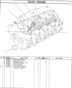
Basic Engine 7
Air Inlet and Exhaust System 10
Clean Emissions Module 15
Cooling System 17
Lubrication System 19
Electrical System 19
Cleanliness of Fuel System Components 20
Fuel Injection 21
Electronic Control System 28
Power Sources 41
Glossary of Electronic Control Terms 45
Testing and Adjusting Section
Fuel System
Fuel System – Inspect 50
Air in Fuel – Test 50
Finding Top Center Position for No 1 Piston 52
Fuel Injection Timing – Check 52
Fuel Quality – Test 53
Fuel System – Prime 54
Fuel System Pressure – Test 55
Gear Group (Front) – Time 58
Air Inlet and Exhaust System
Air Inlet and Exhaust System – Inspect 59
Turbocharger – Inspect 59
Exhaust Cooler (NRS) – Test 62
Diesel Particulate Filter – Clean 63
Compression – Test 64
Engine Valve Lash – Inspect 64
Valve Depth – Inspect 65
Valve Guide – Inspect 66
Lubrication System
Engine Oil Pressure – Test 68
Engine Oil Pump – Inspect 68
Excessive Bearing Wear – Inspect 68
Excessive Engine Oil Consumption – Inspect 68
Increased Engine Oil Temperature – Inspect 69
Cooling System
Cooling System – Check 70
Cooling System – Inspect 70
Cooling System – Test 71
Engine Oil Cooler – Inspect 72
Water Temperature Regulator – Test 73
Water Pump – Inspect 73
Basic Engine
Position the Valve Mechanism Before
Maintenance Procedures 74
Piston Ring Groove – Inspect 74
Connecting Rod – Inspect 75
Cylinder Block – Inspect 75
Cylinder Head – Inspect 75
Piston Height – Inspect 76
Flywheel – Inspect 77
Flywheel Housing – Inspect 78
Gear Group – Inspect 79
Crankshaft Pulley – Check 80
Electrical System
Alternator – Test 81
Battery – Test 83
Charging System – Test 83
V-Belt – Test 84
Electric Starting System – Test 85
Index Section
Index 89
Troubleshooting Section
Electronic Troubleshooting
Welding Precaution 5
System Overview 5
Glossary 10
Electronic Service Tools 14
Indicator Lamps 16
Replacing the ECM 18
Self-Diagnostics 19
Sensors and Electrical Connectors 20
Engine Wiring Information 26
ECM Harness Connector Terminals 36
Programming Parameters
Programming Parameters 37
Flash Programming 37
Injector Code – Calibrate 37
Mode Switch Setup 38
Throttle Setup 39
Multiposition Switch Setup 41
Customer Specified Parameters
Customer Specified Parameters 42
Customer Specified Parameters Table 46
Customer Specified Parameters Worksheet 49
System Configuration Parameters
System Configuration Parameters 51
Symptom Troubleshooting
Acceleration Is Poor or Throttle Response Is
Poor 52
Alternator Is Noisy 54
Alternator Problem 54
Battery Problem 55
Coolant Contains Oil 55
Coolant Level Is Low 56
Coolant Temperature Is High 56
Crankcase Breather Ejects Oil 58
Cylinder Is Noisy 60
Diesel Particulate Filter Active Regeneration
Occurrence Is Excessive 60
Diesel Particulate Filter Active Regeneration
Was Interrupted 61
Diesel Particulate Filter Collects Excessive
Soot 62
Diesel Particulate Filter Has Differential Pressure
Problem 64
Diesel Particulate Filter Temperature Is Low 66
ECM Does Not Communicate with Other
Modules 67
Electronic Service Tool Does Not
Communicate 67
Engine Cranks but Does Not Start 68
Engine Does Not Crank 72
Engine Has Early Wear 73
Engine Has Mechanical Noise (Knock) 73
Engine Misfires, Runs Rough or Is Unstable 74
Engine Overspeeds 76
Engine Shutdown Occurs Intermittently 76
Engine Speed Does Not Change 78
Engine Stalls at Low RPM 78
Engine Top Speed Is Not Obtained 79
Engine Vibration Is Excessive 82
Exhaust Has Excessive Black Smoke 83
Exhaust Has Excessive White Smoke 84
Fuel Consumption Is Excessive 86
Fuel Contains Water 88
Fuel Rail Pressure Problem 89
Fuel Temperature Is High 92
Inlet Air Is Restricted 93
Inlet Air Temperature Is High 93
Intake Manifold Air Pressure Is High 94
Intake Manifold Air Pressure Is Low 95
Intake Manifold Air Temperature Is High 97
Oil Consumption Is Excessive 97
Oil Contains Coolant 98
Oil Contains Fuel 99
Oil Pressure Is Low 101
Power Is Intermittently Low or Power Cutout Is
Intermittent 103
Valve Lash Is Excessive 105
Troubleshooting with a Diagnostic Code
Diagnostic Trouble Codes 106
Diagnostic Functional Tests
5 Volt Sensor Supply Circuit – Test 114
Analog Throttle Position Sensor Circuit – Test 120
CAN Data Link Circuit – Test 126
ECM Memory – Test 129
Electrical Connectors – Inspect 131
Electrical Power Supply – Test 134
Engine Pressure Sensor Open or Short Circuit –
Test 138
Engine Pressure Sensor Open or Short Circuit –
Engine Speed/Timing Sensor Circuit – Test 153
Engine Temperature Sensor Open or Short
Circuit – Test 161
Glow Plug Starting Aid – Test 171
Idle Validation Switch Circuit – Test 178
Ignition Keyswitch Circuit and Battery Supply
Circuit – Test 184
Indicator Lamp Circuit – Test 191
Injector Data Incorrect – Test 196
Injector Solenoid Circuit – Test 199
Mode Selection Circuit – Test 206
Motorized Valve – Test 211
Oxygen Level – Test 218
PTO Switch Circuit – Test 223
Solenoid Valve – Test 227
Start Relay Circuit – Test 234
Switch Circuits – Test 240
Switch Circuits – Test 245
Throttle Switch Circuit – Test 250
Valve Position Sensor – Test 254
Water In Fuel Sensor – Test 261
Index Section
Index 266
Foreword 4
Safety Section
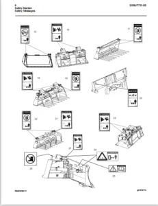
Safety Messages 5
General Hazard Information 6
Burn Prevention 9
Fire Prevention and Explosion Prevention 10
Crushing Prevention and Cutting Prevention 12
Mounting and Dismounting 12
High Pressure Fuel Lines 12
Before Starting Engine 14
Engine Starting 14
Engine Stopping 14
Electrical System 15
Engine Electronics 16
Product Information Section
Model Views 17
Product Identification Information 23
Operation Section
Lifting and Storage 27
Gauges and Indicators 29
Features and Controls 31
Engine Diagnostics 45
Engine Starting 49
Engine Operation 52
Engine Stopping 56
Cold Weather Operation 58
Maintenance Section
Refill Capacities 62
Maintenance Recommendations 76
Maintenance Interval Schedule 78
Warranty Section
Warranty Information 110
Reference Information Section
Reference Materials 114
Index Section
Index 115
DESCRIPTION:
Caterpillar Lift Truck DP50N1 Service Manuals – Complete Set – PDF DOWNLOAD
FOREWORD:
- This service manual describes the specifications, maintenance, and service procedures for 854F and 854E Diesel Engine of Cat Lift Trucks. To maintain the performance of the engine for many years and to ensure safe operation, it is important to use the engine correctly and conduct regular inspection and maintenance, and also to take necessary measures which involves the disassembly, inspection, repair, and assembly of the engine and engine parts.
- Read this manual carefully and understand the work procedures fully before disassembling, inspecting, repairing, or assembling the engine. The contents of this manual are based on the engine models that are being produced at the time of publication. Due to improvements made thereafter, the actual engine that you work on may differ partially from the one described in this manual.
854F model is for DP40N1-DP55N1/DP40NB-DP55NB Chassis Service Manual.
854E model is for DP70N Chassis Service Manual.
CATERPILLAR LIFT TRUCK DP50N1 SERVICE MANUALS – COMPLETE SET – PDF DOWNLOAD:
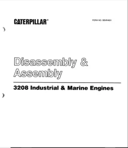
IMAGES PREVIEW OF THE MANUAL:
PLEASE NOTE:
- This is not a physical manual but a digital manual – meaning no physical copy will be couriered to you. The manual can be yours in the next 2 mins as once you make the payment, you will be directed to the download page IMMEDIATELY.
- This is the same manual used by the dealers inorder to diagnose your vehicle of its faults.
- Require some other service manual or have any queries: please WRITE to us at [email protected]
S.V