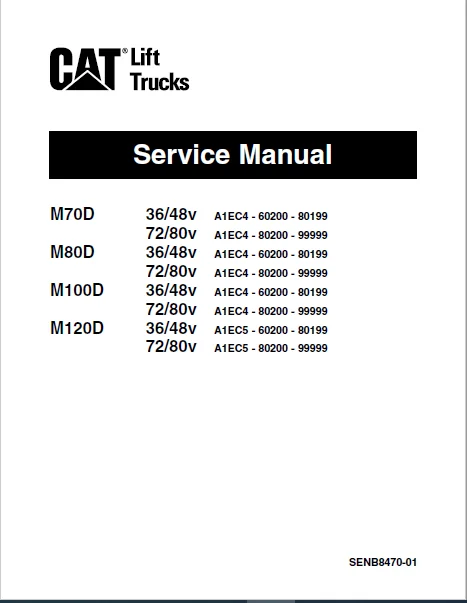
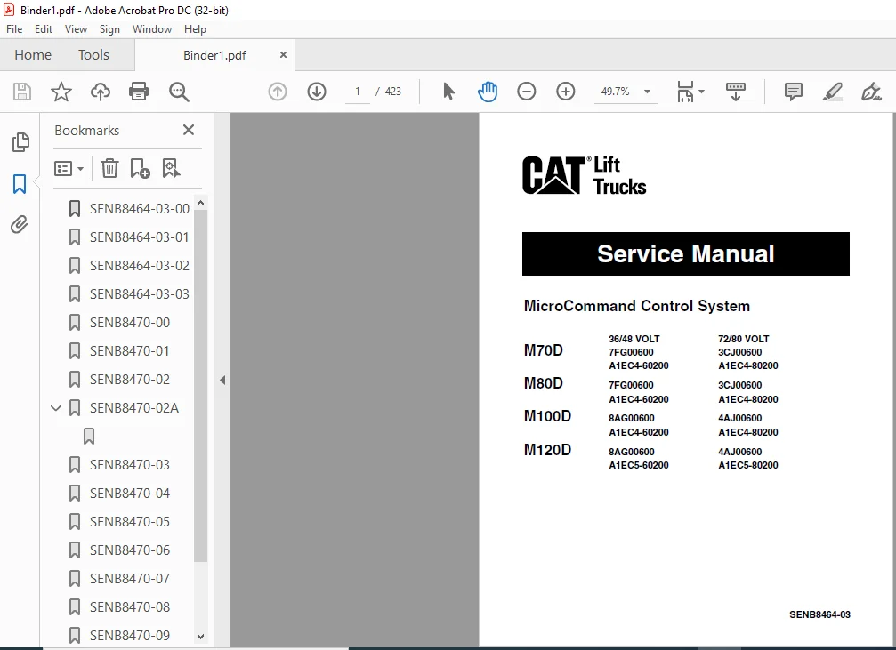
Caterpillar M100D 36-48V Lift Trucks Service Manuals – PDF DOWNLOAD
Original price was: $89.95.$27.95Current price is: $27.95.
Caterpillar M100D 36-48V Lift Trucks Service Manuals – PDF DOWNLOAD
All S/N & Models covered
Description
Caterpillar M100D 36-48V Lift Trucks Service Manuals – PDF DOWNLOAD
DESCRIPTION:
Caterpillar M100D 36-48V Lift Trucks Service Manuals – PDF DOWNLOAD
Important Safety Information :
Most accidents involving product operation, maintenance and repair are caused by failure to observe basic safety rules or precautions. An accident can often be avoided by recognizing potentially hazardous situations before an accident occurs. A person must be alert to potential hazards. This person should also have the necessary training, skills and tools to perform these functions properly.
- Improper operation, lubrication, maintenance or repair of this product can be dangerous and could result in injury or death. Do not operate or perform any lubrication, maintenance or repair of this product until you have read and understood the operation, lubrication, maintenance and repair information. Safety precautions and warnings are provided in this manual and on the product.
- If these hazard warnings are not heeded, bodily injury or death could occur to you or other persons. The hazards are identified by the “Safety Alert Symbol” and followed by a “Signal Word” such as “WARNING” as shown below.
TABLE OF CONTENTS:
Caterpillar M100D 36-48V Lift Trucks Service Manuals – PDF DOWNLOAD
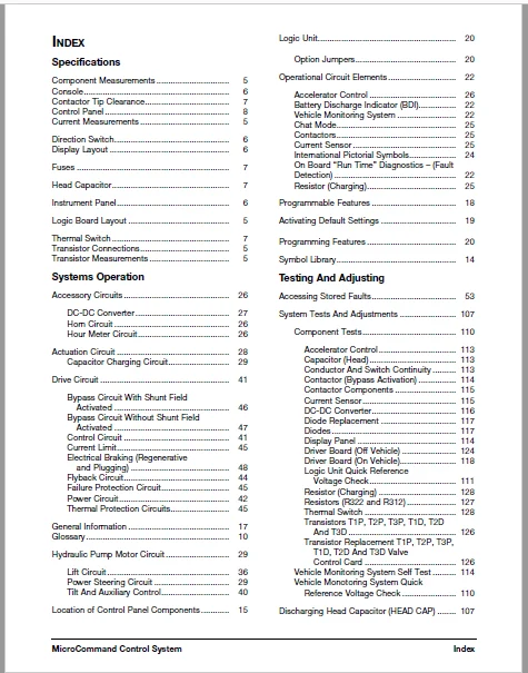
Specifications
Component Measurements 5
Console 6
Contactor Tip Clearance 7
Control Panel 8
Current Measurements 5
Direction Switch 6
Display Layout 6
Fuses 7
Head Capacitor 7
Instrument Panel 6
Logic Board Layout 5
Thermal Switch 7
Transistor Connections 5
Transistor Measurements 5
Systems Operation
Accessory Circuits 26
DC-DC Converter 27
Horn Circuit 26
Hour Meter Circuit 26
Actuation Circuit 28
Capacitor Charging Circuit 29
Drive Circuit 41
Bypass Circuit With Shunt Field
Activated 46
Bypass Circuit Without Shunt Field
Activated 47
Control Circuit 41
Current Limit 45
Electrical Braking (Regenerative
and Plugging) 48
Flyback Circuit 44
Failure Protection Circuit 45
Power Circuit 42
Thermal Protection Circuits 45
General Information 17
Glossary 10
Hydraulic Pump Motor Circuit 29
Lift Circuit 36
Power Steering Circuit 29
Tilt And Auxiliary Control 40
Location of Control Panel Components 15
Logic Unit 20
Option Jumpers 20
Operational Circuit Elements 22
Accelerator Control 26
Battery Discharge Indicator (BDI) 22
Vehicle Monitoring System 22
Chat Mode 25
Contactors 25
Current Sensor 25
International Pictorial Symbols 24
On Board “Run Time” Diagnostics – (Fault
Detection) 22
Resistor (Charging) 25
Programmable Features 18
Activating Default Settings 19
Programming Features 20
Symbol Library 14
Testing And Adjusting
Accessing Stored Faults 53
System Tests And Adjustments 107
Component Tests 110
Accelerator Control 113
Capacitor (Head) 113
Conductor And Switch Continuity 113
Contactor (Bypass Activation) 114
Contactor Components 115
Current Sensor 115
DC-DC Converter 116
Diode Replacement 117
Diodes 117
Display Panel 114
Driver Board (Off Vehicle) 124
Driver Board (On Vehicle) 118
Logic Unit Quick Reference
Voltage Check 111
Resistor (Charging) 128
Resistors (R322 and R312) 127
Thermal Switch 128
Transistors T1P, T2P, T3P, T1D, T2D
And T3D 126
Transistor Replacement T1P, T2P, T3P,
T1D, T2D And T3D Valve
Control Card 126
Vehicle Monitoring System Self Test 114
Vehicle Monotoring System Quick
Reference Voltage Check 110
Discharging Head Capacitor (HEAD CAP) 107
MicroCommand Control System Index
Electrical System Adjustments 129
Accelerator Control Linkage 129
Battery Discharge Indicator (BDI)
Adjustment 134
Bypass Dropout Adjustment 136
Current Limit Test And Adjustment 134
Electrical Braking (Regen) Current Test
And Adjustment 136
Final Logic Board Potentiometer
Adjustments 134
Lift Sensor 130
Parking Brake Switch 129
Rapid Tune-up Procedure 133
Tilt And Auxiliary Speed Adjustment 132
Tilt And Auxiliary Switches 131
Valve Control Card 130
Logics Removal 108
“Run Time” Tests 108
Control Panel Overtemperature
Protection 110
Drive Power Circuit Failure Protection,
Display = “F&2” 109
Drive Shunt Field Power Protection,
Display = “F&b” 109
Electrically Assisted Braking Failure
Protection, Display = “F&d” 109
Key ON, No Operator Warning,
Display = “E” (Flashing) 108
Hydraulic Pump Power Circuit Failure,
Display = “F&3” 109
Hydraulic Pump Shunt Field Failure
Protection, Display = “F&9” 109
Static Return To Off (SRO),
Display = “E” (Not Flashing) 108
Test Equipment 107
Troubleshooting 54
Control And Power System Operational
Checks 56
Built-In Diagnostic Operation 57
Preparation Tests And Checks 54
Troubleshooting Check Lists 54
Troubleshooting Problem List 63
Caterpillar M100D 36-48V Lift Trucks Service Manual
CHAPTER 1 GENERAL
Scope 1-1
Truck Models Covered 1-1
CHAPTER 2 ELECTRICAL
Electrical 2-1
MicroCommand™ Control Panel 2-1
Battery 2-1
Remove and Install Battery 2-1
Display Panel 2-2
Remove and Install Display 2-2
Directional Control 2-3
Remove & Install Directional Control 2-3
Logic Unit 2-3
Remove & Install Logic Unit 2-3
Control Panel 2-4
Remove & Install Control Panel 2-4
Accelerator Control Group 2-5
Remove and Install Accelerator Control Group 2-5
Capacitors 2-5
Remove & Install Capacitors 2-5
D5D – Diode Five Drive 2-6
Remove & Install D5D – Diode Five Drive 2-6
D4D – Diode Four Drive 2-7
Remove & Install D4D – Diode Four Drive 2-7
D4P – Diode Four Drive 2-7
Remove & Install D4P – Diode Four Drive 2-7
Resistors 2-8
Remove & Install Resistors 2-8
Transistors 2-9
Remove & Install Transistors 2-9
Regenerative Contactor 2-9
Remove & Install Regenerative Contactor 2-9
Line Contactor 2-10
Remove & Install Line Contactor 2-10
TABLE OF CONTENTS
TABLE OF CONTENTS
Bypass Contactor 2-11
Remove & Install Bypass Contactor 2-11
Lift Contactor 2-11
Remove & Install Lift Contactor 2-11
Contactors (Regenerative, Bypass, Line and Lift) 2-12
Disassemble and Assemble Contactors (Regenerative, Bypass, Line and Lift) 2-12
Line Fuse 2-13
Remove & Install Line Fuse 2-13
Contactors (Forward and Reverse) 2-14
Remove & Install Contactors (Forward & Reverse) 2-14
Disassemble & Assemble Contactors (Forward and Reverse) 2-15
Current Sensor 2-16
Remove & Install Current Sensor 2-16
Fuses 2-16
Remove & Install Fuses 1628 – 010 2-16
System Check With Static Diagnostics 2-17
Run Time Diagnostics 2-17
MicroCommand Control System Wiring Connections 2-18
Electrical Schematics 2-19
CHAPTER 3 DIFFERENTIAL AND FINAL DRIVE
Differential 3-1
Specifications 3-1
Description 3-2
Removing Differential 3-3
Installation of Differential 3-3
Disassemble Differential 3-4
Shim Thickness for Differential Bearings 3-7
Bevel Pinion Installation 3-8
Pinion Bearing Preload Adjustment 3-9
Differential Installation 3-11
Gear Clearance (Backlash) Adjustment 3-12
Assembly of Differential 3-13
Final Drive 3-19
Specifications 3-19
Description 3-20
Remove Final Drive 3-21
Install Final Drive 3-22
Wheel Bearing Adjustment 3-22
Universal Joint 3-24
Specifications 3-24
Remove Universal Joint 3-25
Install Universal Joint 3-25
Drive Axle Shaft 3-26
Remove Drive Axle Shaft 3-26
Install Drive Axle Shaft 3-26
Drive Wheel 3-28
Specifications 3-28
CHAPTER 4 DRIVE MOTOR
Drive Motor 4-1
Specifications 4-1
Description 4-2
Disassemble & Assemble Motor 4-3
Brush Inspection 4-5
New Brush Installation 4-6
Armature Tests 4-7
Short Circuit Test 4-7
Ground Test 4-8
Open Circuit Test 4-8
Commutator Inspection 4-10
Commutator Surfaces 4-10
Field Coil and Terminal Tests 4-11
Open Circuit Test 4-11
Ground Test 4-12
Shorts Between Fields Test 4-12
Brush Terminal Test 4-13
Continuity Test 4-13
TABLE OF CONTENTS
TABLE OF CONTENTS
Ground Test 4-13
Brush Holder Test 4-14
Thermal Switch Tests 4-14
Open Circuit Test 4-14
Ground Test 4-15
Brush Life Estimate 4-15
CHAPTER 5 BRAKE SYSTEM
Master Cylinder 5-1
Specifications 5-1
Master Cylinder and Wheel Cylinders 5-1
Description 5-1
Brake Master Cylinder 5-2
Remove & Install Brake Master Cylinder 5-2
Disassemble Brake Master Cylinder 5-3
Assemble Brake Master Cylinder 5-3
Wheel Cylinder 5-3
Remove Wheel Cylinder 5-3
Install Wheel Cylinder 5-4
Disassemble & Assemble Wheel Cylinder 5-4
Wheel Brakes 5-5
Specifications 5-5
Description 5-5
Automatic Adjustment 5-5
Disassemble Wheel Brake Assembly 5-6
Assemble Wheel Brake Assembly 5-6
Parking Brake 5-7
Specifications 5-7
Foot Operated Parking Brake 5-8
Description 5-8
Parking Brake 5-9
Remove Parking Brake 5-9
Install Parking Brake 5-10
Disassemble Parking Brake 5-10
Assemble Parking Brake 5-11
Parking Brake Switch 5-11
Remove and Install Parking Brake 5-11
Brake Lines Group 5-12
Specifications 5-12
Brake Drum Surface Wear 5-12
Specifications 5-12
Testing and Adjusting 5-13
Wheel Brakes 5-13
Brake System Air Removal 5-13
Brake Adjustment 5-14
Brake Adjuster Installation 5-15
Parking Brake 5-16
Parking Brake Test 5-16
Parking Brake Adjustment 5-16
Foot Operated Parking Brake 5-16
Seat Operated Parking Brake 5-17
CHAPTER 6 STEERING SYSTEM
Description 6-1
Steering Cylinder 6-2
Steering Gear 6-2
Specifications 6-2
Steering Gear 6-3
Oil Flow 6-3
Right Turn 6-3
Left Turn 6-4
Dynamic Flow 6-5
Manual Operation of Steering Metering Pump 6-5
Steering Gear 6-6
Remove and Install Steering Gear 6-6
Steering Wheel 6-7
Specifications 6-7
Remove & Install Steering Wheel 6-7
Steer Axle and Wheel 6-8
TABLE OF CONTENTS
TABLE OF CONTENTS
Testing and Adjustments 6-10
Steer Wheel Bearing Adjustment 6-10
Steer Axle Adjustments 6-10
Steer Axle Stops Adjustment 6-10
Steering Knuckle Bearing Preload Adjustment 6-11
Steering System Air Removal 6-11
Steering System Pressure Check 6-12
Steering System Pressure Adjustment 6-14
CHAPTER 7 HYDRAULIC SYSTEM
Basic Oil Flow 7-1
Description 7-1
Hydraulic Pump Motor 7-3
Specifications 7-3
Description 7-4
Remove & Install Hydraulic Pump Motor 7-5
Hydraulic Motor 7-6
Disassemble & Assemble Motor 7-6
Hydraulic Pump 7-8
Specifications 7-8
Remove & Install Hydraulic Pump 7-9
Disassemble & Assemble Hydraulic Pump 7-9
Hydraulic Control Valve 7-10
Specifications 7-10
Hydraulic Control Valve 7-12
Neutral Position 7-12
Lift Position 7-13
Lower Position 7-14
Tilt Back Position 7-15
Tilt Forward Position 7-16
Sideshift Position 7-17
Hydraulic Control Valve 7-18
Remove & Install Hydraulic Control Valve 7-18
Disassemble & Assemble Hydraulic Control Valve 7-18
Hydraulic Filter 7-23
Remove & Install Hydraulic Filter 7-23
Lift Cylinders and Mast 7-24
Standard Lift 7-24
Full Free Lift and Full Free Triple Lift 7-25
Hydraulic Pump Motor 7-27
Testing and Adjusting 7-27
Motor Brushes 7-27
Brush Inspection 7-27
New Brush Installation 7-27
Armature Tests 7-28
Short Circuit Test 7-28
Ground Test 7-28
Open Circuit Test 7-29
Commutator Inspection 7-30
Commutator Surfaces 7-30
Field Coil and Terminal Tests 7-31
Open Circuit Test 7-31
Ground Test 7-31
Shunt Field Tests 7-32
Open Circuit Test 7-32
Ground Test 7-32
Brush Holder Test 7-32
Thermal Switch (Thermostat) Test 7-33
Open Circuit Test 7-33
Ground Test 7-33
Brush Life Estimate 7-33
Testing and Adjusting 7-34
Relief Valve Pressure Check 7-34
Lift and Tilt Relief Valve Check and Adjustment 7-35
Sideshifter Relief Valve Check and Adjustment 7-35
Flow Control Valve Adjustment 7-36
Hydraulic Schematic 7-37
TABLE OF CONTENTS
TABLE OF CONTENTS
CHAPTER 8 TROUBLESHOOTING
Differential and Final Drive 8-1
Drive Motor 8-2
Brake System 8-9
Steering System 8-11
Hydraulic System 8-13
CHAPTER 9 MASTING
Specifications 9-1
Lift Cylinders 9-2
Flow Regulator Valve 9-6
Down Safety Valve 9-7
Removal and Installation
Lift Cylinders – (Dual-Stage Panoramic Mast) (Simplex Mast) 9-8
Lift Cylinders – (Triple-stage Full Free Panoramic Mast) (Duplex and Triplex Mast) 9-11
Tilt Cylinders 9-14
Disassembly (No 1)
Lift Cylinders (Simplex Mast) 9-15
Disassembly (No 2)
Lift Cylinders 9-16
Inspection after Disassembly 9-17
Reassembly 9-17
Diassembly (No 3)
First Lift Cylinders (Duplex Mast, Triplex Mast) 9-19
Key Points for Disassembly 9-19
Diassembly (No 4)
Key Points for Disassembly 9-20
Inspection after Disassembly 9-21
Reassembly
First Lift Cylinders (H40A, J40A, thru J55A) 9-21
Second Lift Cylinders 9-22
Key Points for Reassembly 9-23
Disassembly (No 6)
Second Lift Cylinders – Triplex Mast 9-24
Disassembly (No 7)
Key Points for Disassembly 9-26
Inspection after Disassembly 9-26
Reassembly
Second Lift Cylinders – (J40A) 9-27
Second Lift Cylinders – (J45A, J55A) 9-27
Key Points for Reassembly 9-28
Flow Regulator Valve
Disassembly (No 1) 9-29
Inspection after Disassembly 9-29
Cautions for Assembly 9-29
Flow Regulator Valve Adjustment 9-30
Lift and Tilt Cylinders
Adjusting Mast Tilt Angle (Simple, Duplex) 9-31
Adjusting Mast Tilt Angle (Triplex) 9-31
Lift Cylinder Stroke Adjustment 9-31
Adjustment Method 9-31
Tests 9-31
Troubleshooting 9-33
Service Data 9-36
CHAPTER 10 MAST AND FORKS
Specifications 10-1
Description
Simplex Mast (G40A, G45A, G55A) 10-2
Duplex Mast (H40A) 10-3
Triplex Mast (J40A, J45A, J55A) 10-4
Operation of Dual-stage Full Free Panoramic Mast (Duplex Mast) 10-5
Operation of Triple-stage Full Free Panoramic Mast (Triplex Mast) 10-5
Removal and Installation – Mast and Lift Bracket Assembly
Dual-stage Panoramic Mast (Simplex Mast) 10-6
Suggestions 10-6
Installation 10-8
Tightening Torque 10-8
Dual-stage Full Free Panoramic Mast and Triple Stage Full Free Panoramic Mast 10-9
(Duplex and Triplex Mast)
TABLE OF CONTENTS
TABLE OF CONTENTS
Suggestions for removal 10-9
Installation 10-11
Tightening Torque 10-11
Disassembly and Assembly
Dual Stage Panoramic Mast (Simplex Mast) 10-12
Disassembly 10-12
Suggestions 10-12
Inspection after disassembly 10-13
Length of Lift Chain (per 20 links) 10-14
Reassembly 10-14
Roller Sizes 10-14
Dual Stage Full Free Panoramic Mast (Duplex Mast) 10-16
Disassembly 10-16
Suggestions 10-17
Inspection after disassembly 10-17
Reassembly 10-18
Triple Stage Full Free Panoramic Mast (Triplex Mast) 10-21
Disassembly 10-21
Suggestions 10-22
Inspection after disassembly 10-23
Reassembly 10-23
Inspection and Adjustment
Forks 10-25
Chain, Chain Wheel Support and Chain Wheel 10-26
Chain Tension Adjustment
Dual-stage Panoramic Mast (Simplex Mast) 10-27
Dual-stage Full Free Panoramic Mast (Duplex Mast) 10-28
Triple-stage Full Free Panoramic Mast (Triplex Mast) 10-29
Clearance Adjustment on Lift Bracket 10-30
Mast Clearance Adjustment 10-32
Main Roller Shim Replacement (Simplex Mast) 10-34
Procedure for Replacing Main Roller Shims
[Dual Stage Full Free Panoramic Mast (Duplex Mast)] 10-35
Procedure for Replacing Main Roller Shims
[Triple-stage Full Free Panoramic Mast (Triplex Mast)] 10-36
Mast Strip Adjustment 10-38
Tilt Angle Adjustment 10-38
Lift Cylinder Stroke Adjustment 10-39
Troubleshooting – Mast 10-40
Service Data 10-41
Simplex Mast / Duplex Mast 10-42
Triplex Mast 10-43
CHAPTER 11 SERVICE DATA
Inspection Standards 11-1
Tightening Torques for Standard Bolts 11-2
Periodic Replacement of Parts 11-4
Lubrication Chart 11-
CATERPILLAR M100D 36-48V LIFT TRUCKS SERVICE MANUALS – PDF DOWNLOAD:
IMAGES PREVIEW OF THE MANUAL:
PLEASE NOTE:
- This is not a physical manual but a digital manual – meaning no physical copy will be couriered to you. The manual can be yours in the next 2 mins as once you make the payment, you will be directed to the download page IMMEDIATELY.
- This is the same manual used by the dealers inorder to diagnose your vehicle of its faults.
- Require some other service manual or have any queries: please WRITE to us at [email protected]
S.V