Caterpillar M120D 72-80V Lift Trucks Service Manuals – PDF DOWNLOAD
Original price was: $89.95.$29.95Current price is: $29.95.
Caterpillar M120D 72-80V Lift Trucks Service Manuals – PDF DOWNLOAD
Description
Caterpillar M120D 72-80V Lift Trucks Service Manuals – PDF DOWNLOAD
DESCRIPTION:
Caterpillar M120D 72-80V Lift Trucks Service Manuals – PDF DOWNLOAD
Important Safety Information :
Most accidents involving product operation, maintenance and repair are caused by failure to observe basic safety rules or precautions. An accident can often be avoided by recognizing potentially hazardous situations before an accident occurs. A person must be alert to potential hazards. This person should also have the necessary training, skills and tools to perform these functions properly.
- Improper operation, lubrication, maintenance or repair of this product can be dangerous and could result in injury or death. Do not operate or perform any lubrication, maintenance or repair of this product until you have read and understood the operation, lubrication, maintenance and repair information.
- Safety precautions and warnings are provided in this manual and on the product. If these hazard warnings are not heeded, bodily injury or death could occur to you or other persons. The hazards are identified by the “Safety Alert Symbol” and followed by a “Signal Word” such as “WARNING” as shown below.
TABLE OF CONTENTS:
Caterpillar M120D 72-80V Lift Trucks Service Manuals – PDF DOWNLOAD
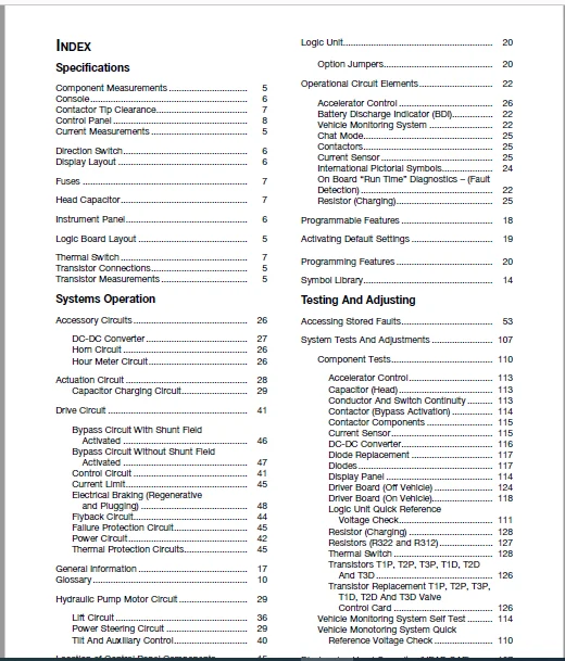
Specifications
Component Measurements 5
Console 6
Contactor Tip Clearance 7
Control Panel 8
Current Measurements 5
Direction Switch 6
Display Layout 6
Fuses 7
Head Capacitor 7
Instrument Panel 6
Logic Board Layout 5
Thermal Switch 7
Transistor Connections 5
Transistor Measurements 5
Systems Operation
Accessory Circuits 26
DC-DC Converter 27
Horn Circuit 26
Hour Meter Circuit 26
Actuation Circuit 28
Capacitor Charging Circuit 29
Drive Circuit 41
Bypass Circuit With Shunt Field
Activated 46
Bypass Circuit Without Shunt Field
Activated 47
Control Circuit 41
Current Limit 45
Electrical Braking (Regenerative
and Plugging) 48
Flyback Circuit 44
Failure Protection Circuit 45
Power Circuit 42
Thermal Protection Circuits 45
General Information 17
Glossary 10
Hydraulic Pump Motor Circuit 29
Lift Circuit 36
Power Steering Circuit 29
Tilt And Auxiliary Control 40
Location of Control Panel Components 15
Logic Unit 20
Option Jumpers 20
Operational Circuit Elements 22
Accelerator Control 26
Battery Discharge Indicator (BDI) 22
Vehicle Monitoring System 22
Chat Mode 25
Contactors 25
Current Sensor 25
International Pictorial Symbols 24
On Board “Run Time” Diagnostics – (Fault
Detection) 22
Resistor (Charging) 25
Programmable Features 18
Activating Default Settings 19
Programming Features 20
Symbol Library 14
Testing And Adjusting
Accessing Stored Faults 53
System Tests And Adjustments 107
Component Tests 110
Accelerator Control 113
Capacitor (Head) 113
Conductor And Switch Continuity 113
Contactor (Bypass Activation) 114
Contactor Components 115
Current Sensor 115
DC-DC Converter 116
Diode Replacement 117
Diodes 117
Display Panel 114
Driver Board (Off Vehicle) 124
Driver Board (On Vehicle) 118
Logic Unit Quick Reference
Voltage Check 111
Resistor (Charging) 128
Resistors (R322 and R312) 127
Thermal Switch 128
Transistors T1P, T2P, T3P, T1D, T2D
And T3D 126
Transistor Replacement T1P, T2P, T3P,
T1D, T2D And T3D Valve
Control Card 126
Vehicle Monitoring System Self Test 114
Vehicle Monotoring System Quick
Reference Voltage Check 110
Discharging Head Capacitor (HEAD CAP) 107
MicroCommand Control System Index
Electrical System Adjustments 129
Accelerator Control Linkage 129
Battery Discharge Indicator (BDI)
Adjustment 134
Bypass Dropout Adjustment 136
Current Limit Test And Adjustment 134
Electrical Braking (Regen) Current Test
And Adjustment 136
Final Logic Board Potentiometer
Adjustments 134
Lift Sensor 130
Parking Brake Switch 129
Rapid Tune-up Procedure 133
Tilt And Auxiliary Speed Adjustment 132
Tilt And Auxiliary Switches 131
Valve Control Card 130
Logics Removal 108
“Run Time” Tests 108
Control Panel Overtemperature
Protection 110
Drive Power Circuit Failure Protection,
Display = “F&2” 109
Drive Shunt Field Power Protection,
Display = “F&b” 109
Electrically Assisted Braking Failure
Protection, Display = “F&d” 109
Key ON, No Operator Warning,
Display = “E” (Flashing) 108
Hydraulic Pump Power Circuit Failure,
Display = “F&3” 109
Hydraulic Pump Shunt Field Failure
Protection, Display = “F&9” 109
Static Return To Off (SRO),
Display = “E” (Not Flashing) 108
Test Equipment 107
Troubleshooting 54
Control And Power System Operational
Checks 56
Built-In Diagnostic Operation 57
Preparation Tests And Checks 54
Troubleshooting Check Lists 54
Troubleshooting Problem List 63
CATERPILLAR M120D 72-80V LIFT TRUCKS SERVICE MANUALS – PDF DOWNLOAD:
IMAGES PREVIEW OF THE MANUAL:
PLEASE NOTE:
- This is the SAME manual used by the dealers to troubleshoot any faults in your vehicle. This can be yours in 2 minutes after the payment is made.
- Contact us at [email protected] should you have any queries before your purchase or that you need any other service / repair / parts operators manual.
S.V