Caterpillar NR25KH Lift Trucks Operation & Maintenance Manual – PDF DOWNLOAD
Original price was: $89.95.$24.95Current price is: $24.95.
Caterpillar NR25KH Lift Trucks Operation & Maintenance Manual – PDF DOWNLOAD
Description
Caterpillar NR25KH Lift Trucks Operation & Maintenance Manual – PDF DOWNLOAD
DESCRIPTION:
Caterpillar NR25KH Lift Trucks Operation & Maintenance Manual – PDF DOWNLOAD
Safety instructions
Instructions for site supervisor
• Familiarise yourself with the operating instructions and its contents.
• Train the operator on the use, safety, and maintenance aspects of the truck.
• Control that the operating and maintenance instructions, and safety regulations are observed.
Occupational safety
• Keep the truck clean and in good working order. Carry out the daily and weekly maintenance checks in
accordance with the maintenance schedule and instructions to avoid faults and operational errors.
• If you notice any faults or deficiencies that may effect the safe operation of the truck, take the truck out of
operation until the faults or deficiencies have been remedied.
• Do not repair anything on the truck without permission from the site supervisor.
• In the event of a malfunction, switch off the power and notify the site supervisor.
• When using the truck, you are responsible for both your own safety and the safety of your environment.
• Immediately notify the site supervision of any accidents or injuries. In such a case, leave the truck at the place
of the accident.
• The truck can only be used for purposes corresponding with its equipment.
Truck operator
Requirements:
• At least 18 years old
• Sufficient physical (e.g. good hearing and sight) and mental abilities for operating the truck without risks
• Appropriately trained; familiar with operating, safety and maintenance instructions
• Has permission from the site supervision to operate the truck
• Knows and masters the drive and operational features of the truck
TABLE OF CONTENTS:
Caterpillar NR25KH Lift Trucks Operation & Maintenance Manual – PDF DOWNLOAD
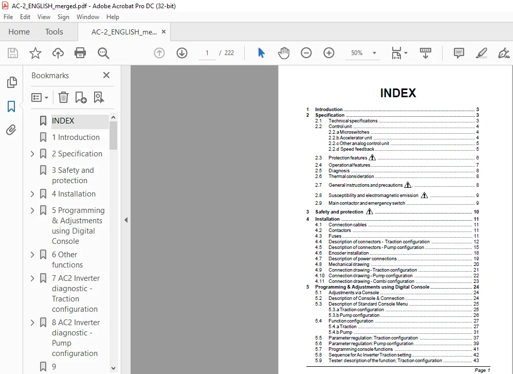
INDEX..................................................................................  1
1 Introduction ........................................................................  3
2 Specification .......................................................................  3
	2.1 Technical specifications ......................................................  3
	2.2 Control unit ..................................................................  4
		2.2.a Microswitches ...........................................................  4
		2.2.b Accelerator unit ........................................................  4
		2.2.c Other analog control unit ...............................................  5
		2.2.d Speed feedback ..........................................................  5
	2.3 Protection features ...........................................................  6
	2.4 Operational features ..........................................................  7
	2.5 Diagnosis .....................................................................  8
	2.6 Thermal consideration .........................................................  8
	2.7 General instructions and precautions. .........................................  8
	2.8 Susceptibility and electromagnetic emission  ..................................  9
	2.9 Main contactor and emergency switch ...........................................  9
3 Safety and protection  .............................................................. 10
4 Installation ........................................................................ 11
	4.1 Connection cables ............................................................. 11
	4.2 Contactors .................................................................... 11
	4.3 Fuses ......................................................................... 11
	4.4 Description of connectors -  Traction configuration ........................... 12
	4.5 Description of connectors - Pump configuration ................................ 15
	4.6 Encoder installation .......................................................... 18
	4.7 Description of power connections .............................................. 19
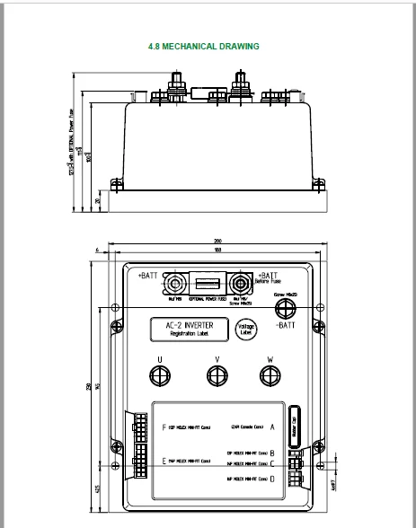
	4.8 Mechanical drawing ............................................................ 20
	4.9 Connection drawing - Traction configuration ................................... 21
	4.10 Connection drawing - Pump configuration ...................................... 22
	4.11 Connection drawing - Combi configuration ..................................... 23
5 Programming & Adjustments using Digital Console ..................................... 24
	5.1 Adjustments via Console ....................................................... 24
	5.2 Description of Console & Connection ........................................... 24
	5.3 Description of Standard Console Menu .......................................... 25
		5.3.a Traction configuration .................................................. 25
		5.3.b Pump configuration ...................................................... 26
	5.4 Function configuration ........................................................ 27
		5.4.a Traction ................................................................ 27
		5.4.b Pump .................................................................... 31
	5.5 Parameter regulation: Traction configuration .................................. 37
	5.6 Parameter regulation: Pump configuration ...................................... 39
	5.7 Programming console functions ................................................. 41
	5.8 Sequence for Ac Inverter Traction setting ..................................... 42
	5.9 Tester: description of the function; Traction configuration ................... 43
	5.10 Tester: description of the function; Pump configuration ...................... 45
6 Other functions ..................................................................... 47
	6.1 Description of the Console Save function ...................................... 47
	6.2 Description of Console Restore function. ...................................... 48
	6.3 Description of Alarms menu .................................................... 49
	6.4 Description of Console Program Vacc function .................................. 50
7 AC2 Inverter diagnostic - Traction configuration .................................... 51
	7.1 Analysis of alarms displayed on console ....................................... 51
8 AC2 Inverter diagnostic - Pump configuration ........................................ 55
	8.1 Analysis of alarms displayed on console ....................................... 55
9 Recommended Spare parts for inverter ................................................ 59
10 Periodic Maintenance to be repeated at times indicated ............................. 60
Indice................................................................................. 72
	Introduction  ..................................................................... 74
	1  System components .............................................................. 75
		 1.1  Steering servo motor control unit ....................................... 75
		 1.2  Steer angle position potentiometer ...................................... 76
		 1.3  Operator console ........................................................ 76
		 1.4  AC steering servo motor ................................................. 76
		 1.5  Steering handle ......................................................... 76
		 1.6  Motor shaft encoder ..................................................... 77
	2  Electrical specifications ...................................................... 78
		 2.1  Battery voltage range ................................................... 78
		 2.2  Steer motor current range ............................................... 78
		2.3  Command device specifications ............................................ 78
			  2.3.1 Tacho generator or stepper motor .................................. 78
			  2.3.2 Automatic centering potentiometer ................................. 79
	3  Mechanical specifications ...................................................... 80
	4  System description ............................................................. 81
		 4.1  Manual steering with tacho-generator or stepper motor ................... 81
		 4.2  Automatic centering ..................................................... 81
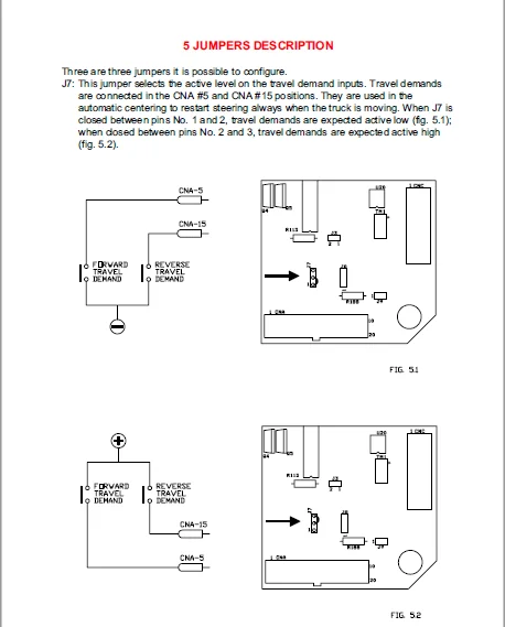
	5  Jumpers description ............................................................ 82
	6  Power connection diagram ....................................................... 84
		 6.1  Electrical drawing ...................................................... 85
			  6.1.1 Tacho-generator steering .......................................... 85
			  6.1.2 Stepper motor steering ............................................ 86
			6.1.3 Tacho-generator steering with automatic centering ................... 87
			  6.1.4 Stepper motor steering with automatic centering ................... 88
			  6.1.5 Interface description ............................................. 89
	7  One shot installation procedure ................................................ 91
	8  Description of connectors ...................................................... 92
		 8.1  CNB connector ........................................................... 92
		 8.2  CNA connector ........................................................... 94
	9  Setting the steering ........................................................... 96
		 9.1  Tacho-generator or stepper motor controlled steering  ................... 96
		 9.2  Automatic centering ..................................................... 96
		 9.3  Steer angle indicator gauge ............................................. 97
	10  Zapi hand set description ..................................................... 98
		 10.1  Manual mode steering option - hand set function map .................... 99
		 10.2  Manual mode steering option and automatic centering - ..................100
		 10.3  Main menu "Parameters list" ............................................101
		 10.4  Parameters in set model 0 (tacho-generator or stepper motor only) ......101
		 10.5  Parameters in set model 1 (tacho-generator or stepper motor and ........103
		 10.6  Main menu: "Tester" functions list .....................................104
		 10.7  Config menu: "Set options" functions list ..............................106
		 10.8  Config menu: "Adjustments" functions list ..............................108
		 10.9  Config menu: "Set model" ...............................................111
		 10.10 Maximum current adjustment .............................................111
	11  EPS-AC alarm list .............................................................112
		 11.1  Analysis of alarms displayed on console ................................112
			  11.1.1 One blink alarms .................................................112
			  11.1.2 Two blinks alarms ................................................115
			  11.1.3 Three blinks alarms ..............................................116
			11.1.4 Four blinks alarms .................................................117
			11.1.5 Five blinks alarms .................................................117
			  11.1.6 Six blinks alarms ................................................118
	12  Safety controls and their use .................................................120
		12.1  Safety controls in tacho-generator and automatic centering steering .....120
		12.2  Safety on motor wires broken ............................................120
		 12.3  Safety on failure of the steering tacho-generator ......................120
			12.3.1 Safety on failures of the steering stepper motor ...................120
		12.4  Safety on the presence of current when the steering motor is at rest ....120
		 12.5  Safety on the presence of phase voltage when the steering ..............121
		 12.6  Safety on pot wires broken (for automatic centering operation) .........121
		12.7  Cross diagnosis between master and supervisor microcontroller ...........121
Index..................................................................................123
1 Introduction to Zapi can system .....................................................124
2 General characteristic ..............................................................125
	2.1 Functional characteristics ....................................................125
	2.2 Input .........................................................................125
3 Operational features ................................................................126
	3.1 Mechanical drawing ............................................................127
4 Safety and protection  ..............................................................128
5 Connectors description ..............................................................129
	5.1 Connector CNA: AMP SAAB 42 poles ..............................................129
	5.2 Connector CNB: AMP SAAB 16 poles ..............................................130
	5.3 Connector CNC: AMP SAAB 6 poles ...............................................131
6 Programming and adjustments using digital console ...................................132
	6.1 Adjustments via console .......................................................132
	6.2 Description of console and connection .........................................132
	6.3 Description of standard console menu ..........................................133
	6.4 Mhyrio functional .............................................................134
	6.5 Description of programmable functions (options) ...............................135
	6.6 Description of parameters that may be programmed (parameter change) ...........137
	6.7 Adjustments table .............................................................138
	6.8  Alarms associated with the flashing red led ..................................140
	6.9 Analysis of alarms displayed on the console ...................................140
	6.10  Description of the tester function ..........................................141
	6.11 Description of the console save function .....................................144
	6.12 Description of the console restore function ..................................144
	6.13 Description of the set model Function ........................................145
	6.14 Description of alarms menu ...................................................147
7 Periodic maintenance to be repeated at times indicated ..............................148
Index..................................................................................154
1 SICOS DESCRIPTION....................................................................155
	1.1 GENERAL FEATURES...............................................................155
	1.2 GRAPHICAL DISPLAY DESCRIPTION..................................................156
		1.2.a Direction indication.....................................................156
		1.2.b Battery indication.......................................................156
		1.2.c Hourmeter indication.....................................................157
		1.2.d Truck speed indication...................................................157
		1.2.e Height indication........................................................157
		1.2.f Alarm indication.........................................................157
		1.2.g Symbol bar...............................................................158
		1.2.h Preselector or Customer Logo.............................................158
2 DISPLAY MENU DESCRIPTION.............................................................159
	2.1 SELECTION BUTTONS CONTROL......................................................159
	2.2 MAIN MENU......................................................................159
	2.3 SUBMENU........................................................................160
		2.3.a Tester Master............................................................160
		2.3.b Tester Slave.............................................................161
		2.3.c Autoteaching.............................................................162
		2.3.d Alarms...................................................................163
		2.3.e Lift Limit...............................................................164
		2.3.f Program Offset...........................................................164
3 CONSOLE DESCRIPTION..................................................................165
	3.1 SICOS "TESTER" MENU............................................................165
	3.2 SICOS "PARAMETER CHANGE" MENU..................................................166
	3.3 SICOS "SET MODEL" MENU.........................................................166
	3.4 SICOS "SET OPTION" MENU........................................................167
	3.5 SICOS "ADJUSTMENT" MENU........................................................168
	3.6 CONSOLE MAP....................................................................169
4 ALARMS...............................................................................170
TS841200...............................................................................175
	3-6777: NR14-25K,KC,KE,KH,KN.......................................................175
		1: POWER SUPPLY 48 V...........................................................175
		2: POWERSUPPLY 12/24V..........................................................176
		3: MAINCIRCUITS................................................................177
		4: DRIVE CIRCUIT 1.............................................................178
		5: DRIVE CIRCUIT 2.............................................................179
		6: STEERING CIRCUIT............................................................180
		7: HYDRAULIC CONTROL CIRCUIT 1.................................................181
		8: HYDRAULIC CONTROL CIRCUIT 2.................................................182
		9: HYDRAULIC CONTROL CIRCUIT 3.................................................183
		10: CONTROL CIRCUIT 1..........................................................184
		11: CONTROL CIRCUIT 2..........................................................185
		12: SIGNAL/LIGHT CIRCUIT.......................................................186
		13: FANS, AUX. DEVICES.........................................................187
		15: WIRE HARNESS W6: RL450681..................................................188
		16: WIRE HARNESS W7: RL450682..................................................189
		17: WIRE HARNESS W8: RL450683..................................................190
		18: WIRE HARNESS W9: RL450684..................................................191
		19: WIRE HARNESS W2  RL450734..................................................192
		20: WIRE HARNESS W5  RL450735..................................................193
		21: WIRE HARNESS W10: RL450804.................................................194
		22: WIRE HARNESS W11: RL450860.................................................195
		23: WIRE HARNESS W16: RL461314.................................................196
TS920101...............................................................................197
	3-6778: REACH COLD STORE MODIFICATION..............................................197
		1: HEATING.....................................................................197
		2: CABIN HEATING...............................................................198
		3: REACH CARRIAGE CABLE........................................................199
		4: HYDRAULIC LEVERS............................................................200
		5: HEATING SUPPLY WIRING.......................................................201
		6: AUXILIARY FAN...............................................................202
CATERPILLAR NR25KH LIFT TRUCKS OPERATION & MAINTENANCE MANUAL – PDF DOWNLOAD:
IMAGES PREVIEW OF THE MANUAL:
PLEASE NOTE:
- This is the same manual used by the dealers to diagnose and troubleshoot your vehicle
- You will be directed to the download page as soon as the purchase is completed. The whole payment and downloading process will take anywhere between 2-5 minutes
- Need any other service / repair / parts manual, please feel free to contact [email protected] . We still have 50,000 manuals unlisted
S.V