Trusted Business
Verified & Licensed
Virus Free Files
100% Safe Downloads
Secure Payment
SSL Protected
Instant Delivery
Available Immediately
Sale!
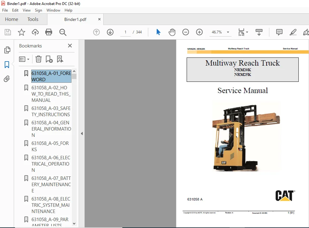
Caterpillar NRM20K NRM25K Multiway Reach Truck Service Manual – PDF DOWNLOAD
Original price was: $89.95.$28.95Current price is: $28.95.
Caterpillar NRM20K NRM25K Multiway Reach Truck Service Manual – PDF DOWNLOAD
Instant PDF Download
Available immediately
Save to Your Device
Download & keep forever
Antivirus Scanned
100% virus-free
Trusted Worldwide
175,000+ customers
Description
Caterpillar NRM20K NRM25K Multiway Reach Truck Service Manual – PDF DOWNLOAD
DESCRIPTION:
Caterpillar NRM20K NRM25K Multiway Reach Truck Service Manual – PDF DOWNLOAD
Foreword :
This service manual is a guide for servicing lift trucks. The long productive life of your lift truck depends on regular and proper servicing, consistent with the instructions provided in this service manual. Before starting to test, repair or rebuild a lift truck, read the respective sections of this manual carefully and familiarize yourself with all of the components.
- The descriptions, illustrations and specifications contained in this manual are for lift trucks with serial numbers in effect at the time of printing.
- The manufacturer reserves the right to change specifications or designs without notice and without incurring obligations. For your convenience, the instructions are grouped by systems as an easy reference. Unauthorized copying and lending of this material is strictly prohibited.
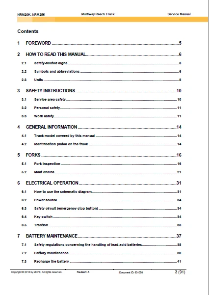
TABLE OF CONTENTS:
Caterpillar NRM20K NRM25K Multiway Reach Truck Service Manual – PDF DOWNLOAD
631058_A-01_FOREWORD.........................................................  1
631058_A-02_HOW_TO_READ_THIS_MANUAL..........................................  6
631058_A-03_SAFETY_INSTRUCTIONS.............................................. 10
631058_A-04_GENERAL_INFORMATION.............................................. 14
631058_A-05_FORKS............................................................ 16
631058_A-06_ELECTRICAL_OPERATION............................................. 31
631058_A-07_BATTERY_MAINTENANCE.............................................. 37
631058_A-08_ELECTRIC_SYSTEM_MAINTENANCE...................................... 45
631058_A-09_PARAMETER_LISTS.................................................. 70
631058_A-10_FAULT_AND_STATE_REPORTS.......................................... 86
631058_A-11_TECHNICAL_DATA................................................... 89
631058_A-12_ANNEX............................................................ 92
AC_SUPERDRIVE_USERS_MANUAL................................................... 96
	Table of Contents........................................................ 97
	Scope of this Manual.....................................................101
	Related Documents........................................................101
	Intended Use of the AC SuperDrive........................................102
	Product Identification...................................................102
	Technical Support........................................................103
	Product Warranty.........................................................104
	Introduction.............................................................105
	Tools and Equipment Required.............................................105
	Orientation..............................................................105
	Clearances for Access and Air Circulation................................105
	Procedure................................................................106
	Introduction.............................................................107
	Tools and Equipment Required.............................................107
	Motor and Battery Connections............................................107
		General..............................................................107
		Making Connections to Terminal Posts.................................109
		Fuses................................................................109
		Inrush Current Limiting Resistance...................................109
		Main Contactor.......................................................109
		Key Start Input......................................................109
	Control and I/O Connections..............................................110
		General..............................................................110
		ID0 and ID1 Inputs...................................................113
		Encoder Signals......................................................113
		Temperature Sensor...................................................113
		CAN Bus Signals......................................................114
		Crimping Contacts onto Signal Conductors.............................114
		Installing Crimped Contacts in Connector Housing.....................114
	General..................................................................117
	Checks Prior to Initial Powerup..........................................117
	Verifying AC SuperDrive Readiness for Operation..........................118
	Configuring the AC SuperDrive for the Application........................118
	Final Operational Checks in Vehicle......................................119
	Introduction.............................................................121
	Periodic Preventive Maintenance..........................................121
	AC SuperDrive Replacement Procedure......................................122
		Drive Removal........................................................122
		Drive Installation...................................................122
	Scope of the Troubleshooting Guide.......................................123
	Using the Troubleshooting Guide..........................................123
		Organization of Troubleshooting Guide................................123
		About Errors and Warnings............................................123
		Error Logging........................................................124
		Using the Troubleshooting Charts.....................................124
	Information for OEMs Preparing User Documentation........................125
	Symptom:   Main Contactor doesn’t close after switching on Key Switch....126
	Symptom:   Fuse to Power Stage is blown..................................127
	Symptom:   AC SuperDrive Status Indicator is blinking or off.............128
	Symptom:   Motor runs only at low speed and with a ticking sound.........129
	Error Code 1:   Pulse Sensor Error.......................................130
	Error Code 2:   Motor Temperature High...................................131
	Warning Code 16:   Power limited due to Motor Overtemp...................131
	Error Code 4:   Heatsink Temperature high................................133
	Warning Code 1:   Power Limited due to Heatsink Overtemp.................133
	Error Code 8:   Overcurrent..............................................135
	Error Code 16:   DC Bus High - hardware detected.........................136
	Error Code 32:   DC Bus High - software detected.........................136
	Error Code 64:   DC Bus Low..............................................137
	Error Code 128:   No Charging DC Bus.....................................137
	Error Code 256:   CAN - too many Errors..................................138
	Error Code 512:   CAN Watchdog Time-out..................................139
	Error Code 1024:   Missing “Okay to Start” from Truck Controller.........140
	Error Code 2048:   Contradictory Commands from Truck Controller..........141
	Error Code 4096:   Potentiometer Values Out of Range.....................142
	Warning Code 2:   Heatsink Temperature Sensor – Open Circuit.............143
	Warning Code 4:   Heatsink Temperature Sensor –  Short Circuit...........143
	Warning Code 8:   Power limited - temp < -20 deg. C......................144
	Warning Code 32:   Motor Temperature Sensor - Open Circuit...............145
	Warning Code 64:   Motor Temperature Sensor  - Short Circuit.............145
	Warning Code 128:   Speed from Truck Controller Out of Range.............146
	Warning Code 256:   Current Calibration Error............................147
	Warning Code 512:   Reverted to Default Parameters.......................148
ADJUSTMENT_INSTRUCTIONS60406.................................................149
APS_ADVANCED_POWER_STEERING_USERS_MANUAL.....................................151
	Table of Contents........................................................153
	Introduction.............................................................157
		About APS Documentation..............................................157
			Scope of this Manual.............................................157
			Intended Use.....................................................157
			Related Documents................................................157
		About the Advanced Power Steering Unit...............................158
			Intended Use.....................................................158
			Safety Instructions..............................................158
				APS Configurations...........................................158
				Product Identification Label.................................159
			Technical Support................................................159
			Product Warranty.................................................160
	APS Installation.........................................................161
		Installing APS in Vehicle............................................161
			Introduction.....................................................161
			Installing the Actuator..........................................161
			Installing a Separately mounted Controller.......................161
		Installing Steering Feedback Sensors.................................162
			Introduction.....................................................162
			Potentiometer....................................................162
				General Information..........................................162
				Mounting.....................................................162
				Steering Feedback Potentiometer Coarse Alignment.............163
			Home Cam with Center Position Sensor.............................163
				General Information..........................................163
				Mounting.....................................................163
			Home Cam with Combination Center/End Limit Sensor................164
				General Information..........................................164
				Mounting.....................................................165
		Installing Steering Input Sensors....................................166
			Introduction.....................................................166
			Stepper Motor....................................................166
				General Information..........................................166
				Mounting.....................................................166
			Joystick or Potentiometer........................................166
				General Information..........................................166
				Mounting.....................................................166
				Steering Input Potentiometer Coarse Electrical Alignment.....166
			Encoder..........................................................167
				General Information..........................................167
				Mounting.....................................................167
		Wiring the APS.......................................................168
			Introduction.....................................................168
			Tools and Equipment Required.....................................168
				Mating Connector and Contacts................................168
				Assembly Tools...............................................168
			Wiring the APS Mating Connector..................................169
				Wire Size Requirements.......................................169
				Crimping Contacts onto Conductors............................169
				Installing Crimped Contacts in Connector Housing.............169
				Mating Connector Pin Assignments.............................170
				APS Mating Connector Latching Mechanism......................171
			Battery Power Connections........................................171
				General......................................................171
				Power Distribution Wiring to  Mating Connector...............172
				Fuses........................................................172
				Inrush Current Limiting Components...........................173
			Sensor, Safety and Communications Wiring.........................173
				CAN Bus......................................................174
				Steering Sensor Wiring Practices.............................175
			Actuator to Separately Mounted Controller Cabling................175
	Startup and Commissioning................................................177
		Initial Startup......................................................177
			General Information..............................................177
			Checks Prior to Initial Powerup..................................177
			Verifying APS Unit Readiness for Operation.......................177
			Configuring the APS for the Application..........................178
			Operational Checks in Vehicle....................................178
	Maintenance..............................................................179
		Maintenance Procedures...............................................179
			Introduction.....................................................179
			Periodic Inspection and Preventive Maintenance...................179
			Steering Feedback Calibration....................................179
				General Information..........................................179
				APS with Potentiometer Steering Feedback.....................179
				APS with Cam and Sensor Steering Feedback....................180
		APS Replacement Procedures...........................................181
			Safety Information...............................................181
			APS with Integrated Controller...................................181
				APS Removal..................................................181
				APS Installation.............................................181
			APS with Separately Mounted Controller...........................182
				Actuator Removal.............................................182
				Actuator Installation........................................182
				Controller Removal...........................................182
				Controller Installation......................................183
	Troubleshooting..........................................................185
		Introduction.........................................................185
			Terms and Definitions............................................185
				General......................................................185
				Errors.......................................................185
				Emergency Messages...........................................185
				Warnings.....................................................185
			Troubleshooting Data Available from APS..........................185
				Error Codes..................................................185
				The Error Log................................................185
				LED Status Indicator.........................................186
		The Troubleshooting Guide............................................187
			General..........................................................187
			Using the Troubleshooting Guide..................................187
			General Troubleshooting Procedure................................187
			Information for OEMs Preparing User Documentation................188
			LED status Indicator is Off......................................189
			2301   High Current Error........................................191
			3101   Voltage Error.............................................192
			4201   High Temp Error...........................................193
			5001   Watchdog Reset............................................194
			5004   Hardware Power Protection Trip............................195
			5007   Safety Out Error..........................................196
			5010   Steer Sensor Error........................................197
			5015   Switch Error..............................................198
			501A   Feedback Sensor Error.....................................200
			5020   EEPROM Error..............................................201
			5021  Motor Error................................................202
			Position Error...................................................203
			8101   Communications Timeout Error..............................205
CANION_USERS_MANUAL..........................................................206
	Table of Contents........................................................208
	Introduction.............................................................210
		About CANION Documentation...........................................212
			Scope of this Manual.............................................210
				Product Identification Label.................................211
	Technical Description....................................................214
		Principles of Operation..............................................214
			Introduction.....................................................216
				General Description..........................................214
			Introduction.....................................................217
			CANION Software..................................................218
				Error Detection..............................................217
	Applications.............................................................220
		Order Picker.........................................................222
		Order Picker.........................................................223
			Reach Truck......................................................224
	Interfacing to CANION....................................................224
		Interfacing Input Devices............................................228
			General..........................................................224
				General......................................................224
		Interfacing Input Devices............................................231
			PWM Outputs......................................................228
				General Hardware Description.................................228
		Interfacing Output Devices...........................................233
			Interfacing CANION in a Truck Can Network........................231
		Can Bus Communications...............................................234
			General Configuration............................................233
	Installation and Wiring..................................................236
		CANION Installation..................................................238
			Mounting CANION in a Vehicle.....................................236
		CANION Installation..................................................240
			Introduction.....................................................238
				Mating Connector and Contacts................................238
	Specifications...........................................................242
		Electrical Power Inputs & Outputs....................................243
DACI2_ENGLISH................................................................244
MULTIWAY_CONTROLLER_ERRORS...................................................271
NRM20K,NRM25K................................................................272
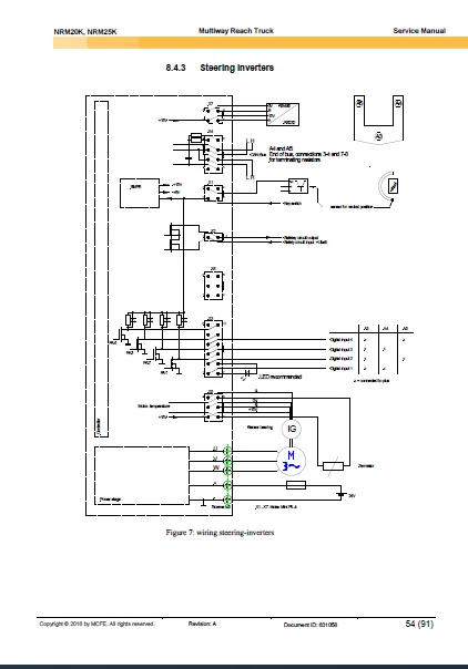
STEERING_INVERTER_ERRORS.....................................................279
TH51_1005....................................................................280
TS761104.....................................................................281
	TS761104.................................................................281
		3-6867: AC-NRM 20K/25K...............................................281
			1: POWERSUPPLY 48V...............................................281
			2: POWERSUPPLY 12/24V............................................282
			3: MAINCIRCUITS..................................................283
			4: DRIVECIRCUIT 1................................................284
			5: DRIVECIRCUIT 2................................................285
			6: STEERING CIRCUIT..............................................286
			7: STEERING CIRCUIT 2............................................287
			8: STEERING CIRCUIT 3............................................288
			9: HYDRAULIC CONTROL CIRCUIT 1...................................289
			10: HYDRAULIC CONTROL CIRCUIT 2..................................290
			11: CONTROL CIRCUIT 1............................................291
			12: CONTROL CIRCUIT 2............................................292
			13: SIGNAL- /LIGHTCIRCUIT........................................293
			14: FANS, AUX.DEVICES............................................294
			15: AUX.DEVICES..................................................295
			16: LAYOUT.......................................................296
			17: LAYOUT.......................................................297
			18: WIRE HARNESS W3: RL468152....................................298
TS1050508_REV_I..............................................................299
WHOMM0001....................................................................318
	ENG-MANUAL TEM...........................................................319
	TEM CAT-kannet...........................................................318
CATERPILLAR NRM20K NRM25K MULTIWAY REACH TRUCK SERVICE MANUAL – PDF DOWNLOAD:
IMAGES PREVIEW OF THE MANUAL:
PLEASE NOTE:
- This is not a physical manual but a digital manual – meaning no physical copy will be couriered to you. The manual can be yours in the next 2 mins as once you make the payment, you will be directed to the download page IMMEDIATELY.
- This is the same manual used by the dealers inorder to diagnose your vehicle of its faults.
- Require some other service manual or have any queries: please WRITE to us at [email protected]
S.V