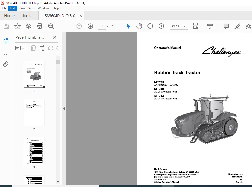
Challenger МТ738 MT740 MT743 Rubber Track Tractor Operator’s Manual 589604D1D
Original price was: $89.95.$28.95Current price is: $28.95.
Challenger МТ738 MT740 MT743 Rubber Track Tractor Operator’s Manual 589604D1D – PDF DOWNLOAD
МТ738
AGCC0738xJxxx1001-
МТ740
AGCC0740xJxxx1001-
МТ743
AGCC0743xJxxx1001-
Description
Challenger МТ738 MT740 MT743 Rubber Track Tractor Operator’s Manual 589604D1D – PDF DOWNLOAD
DESCRIPTION:
Challenger МТ738 MT740 MT743 Rubber Track Tractor Operator’s Manual 589604D1D – PDF DOWNLOAD
МТ738
AGCC0738xJxxx1001-
МТ740
AGCC0740xJxxx1001-
МТ743
AGCC0743xJxxx1001-
- This operator manual uses the latest information available at the time of publication. Read the operator manual carefully before operating the machine. Right-hand and left-hand, as used in the operator manual, is determined Ьу facing the direction that the machine travels when in use.
- Photos, illustrations, and data used in the operator manual were current at the time of publishing. Because of possible production changes, each machine сап vary. Manufacturer reserves the right to redesign and change the machine as necessary without notification.
Important safety information :
Failure to оЬеу basic safety rules and precautions сап cause personal injuries during product operation, maintenance, ог repair. Know dangerous situations before ап injury occurs. А person must Ье alert to possible dangers. This person must also have the necessary training, skills and tools to do these operations correctly.Incorrect operation, lubrication, maintenance ог repair of this product сап Ье dangerous and сап result in injury ог death.
- Read and understand all the information about the operation, lubrication, maintenance, and repair before operating оп this machine. The product and this manual give safety precautions and warnings. Bodily injury ог death сап occur to you ог to other persons if all warnings аге not heeded. Not every possible circumstance that сап involve а potential danger сап Ье anticipated.
- The warnings in this publication and оп the product аге, thus, not all inclusive. If а tool ог procedure, not recommended Ьу AGCO, is used, make sure they аге safe for everyone. Ап operator must make sure the product will not Ье dangerous ог damaged Ьу the operation, lubrication, maintenance ог repair procedures selected. Information, specifications, and illustrations in this publication come from information available at the time of publication production.
- Specifications, torques, pressures, measurements, adjustments, illustrations, and other items сап change at any time. These changes сап change the service that is given to the product. Get the complete and most current information before starting а job. AGCO dealers have the most current information available.
FILE DETAILS:
Challenger МТ738 MT740 MT743 Rubber Track Tractor Operator’s Manual 589604D1D – PDF DOWNLOAD
IMAGES PREVIEW OF THE MANUAL:


TABLE OF CONTENTS:
Challenger МТ738 MT740 MT743 Rubber Track Tractor Operator’s Manual 589604D1D – PDF DOWNLOAD
1 Safety 15
1 1 Safety instructions 17
1 1 1 Operator Manual 1 7
1 1 2 Safety symbol 1 7
1 1 3 Safety messages 1 7
1 1 4 lnformation messages 1 7
1 1 5 Safety signs 1 8
1 1 6 lmportant safety information 1 8
1 1 7 General safety instruction 1 9
1 1 8 Pressurized air 20
1 1 9 Asbestos information 20
1 1 1 0 Electrical storm injury prevention 20
1 1 1 1 Mount and dismount the machine 20
1 1 1 2 Before you start the engine 21
1 1 1 3 Start the engine 21
1 1 1 4 Before operation 21
1 1 1 5 Operating procedures 22
1 1 1 6 Parking 22
1 1 1 7 Prevent contact with power lines 23
1 1 1 8 Operator station 23
1 1 1 9 Cut and crush prevention 23
1 1 20 Rollover protective structure 24
1 1 21 Burn prevention 24
1 1 22 Coolant 24
1 1 23 Oils 25
1 1 24 High pressure lines 25
1 1 25 Fluid penetration 25
1 1 26 Batteries 26
1 1 27 Exhaust fumes 27
1 1 28 Noise prevention 27
1 1 29 Fire and explosion prevention 27
1 1 3 0 Fire extinguisher 28
1 1 3 1 PuЫic road transportation 28
1 2 Safety signs and labels 30
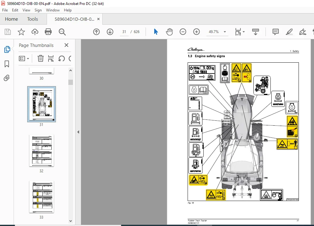
1 3 Engine safety signs 31
1 3 1 Engine oil sign 3 2
1 3 2 Engine oil filter 3 2
1 3 3 Engine air cleaner 3 2
1 3 4 Separator filter 3 2
1 3 5 Fuel filter 3 3
1 3 6 Run-over hazard 3 3
1 3 7 Entanglement 3 3
1 3 8 Entanglement 3 3
1 3 9 High pressure hazard 3 4
1 3 1 0 Hot surface 3 4
1 3 1 1 Hot pressurized liquid hazard 3 4
1 3 1 2 Fuel filter 3 5
1 3 1 3 Separator filter 3 5
1 3 1 4 Engine oil filter 3 5
1 3 1 5 Belt routing 3 5
1 3 1 6 Air conditioning 3 6
1 3 1 7 Explosion hazard 3 6
Rubber Track Tractor
589604010
ТаЬ!е of contents
1 3 1 8 Engine 3 6
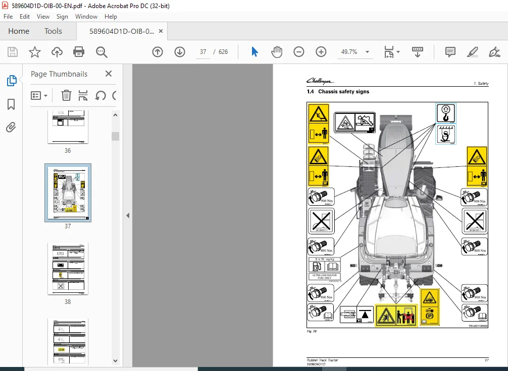
1 4 Chassis safety signs 37
1 4 1 Filter decal 3 8
1 4 2 PIN plate 3 8
1 4 3 Riding hazard 3 8
1 4 4 No step 3 8
1 4 5 Torque 3 9
1 4 6 Torque 3 9
1 4 7 Crush warning 3 9
1 4 8 Torque 3 9
1 4 9 Fall off hazard 4 0
1 4 10 Radiation hazard 4 0
1 4 1 1 T ie down 4 0
1 4 1 2 Lift point 4 0
1 4 1 3 Engine cover support crush hazard 4 1
1 4 1 4 Run over hazard 4 1
1 4 1 5 U ltra low sulfur diesel 4 1
1 4 1 6 Jack points 4 1
1 5 СаЬ safety signs 42
1 5 1 Window exit 4 3
1 5 2 Park brake 4 3
1 5 3 Break glass – exit 4 3
1 5 4 Operators manual 4 3
1 5 5 Bystander notification 4 4
1 5 6 Roll-over hazard 4 4
1 5 7 Run-over hazard 4 4
1 5 8 California Proposition 6 5 4 4
1 6 Hydraulic safety signs 45
1 6 1 Oil level 4 6
1 6 2 High pressure fluid 4 6
1 6 3 Pressurized fluid 4 6
1 7 Electrical safety signs 47
1 7 1 Battery disconnect relay 4 8
1 7 2 1 2 volt 4 8
1 7 3 Battery explosion 4 8
1 7 4 Electrical hazard 4 8
1 7 5 Relay 4 9
1 7 6 Fuse 4 9
1 7 7 Relay 4 9
1 7 8 Engine start switch 4 9
1 8 3-Point linkage safety signs (optional) 50
1 8 1 Power take off 5 0
1 8 2 Rear rollover 5 1
1 8 3 T ie down 5 1
1 8 4 Do not step 5 1
1 8 5 3 -Point linkage lubrication points 5 1
2 lntroduction 53
2 1 Machine identification information 55
2 1 1 Serial number definition 5 6
2 1 2 Machine serial plate 5 7
2 2 lntended use 58
2 3 Proper disposal of waste 59
2 4 Pre-Delivery 60
2 4 1 Pre-delivery checklist 6 0
2 5 Emissions warranty 61
Rubber Тrack Тractor
589604010
2 5 1
2 5 2
ТаЬ!е of contents
U nited States and Canada emission control warranty statement 6 1
California emission control warranty statement 6 4
3 Operation 69
3 1 General inspection 77
3 1 1 Walk-around inspection 7 7
3 2 Seats 79
3 2 1 Basic seat 7 9
3 2 2 Deluxe seat 8 0
3 2 3 lnstructor’s seat 8 2
3 3 Mirrors 83
3 3 1 Adjust the mirrors 8 3
3 4 Console features and controls 84
3 4 1 Steering wheel controls, if equipped 8 4
3 4 2 Adjust the steering wheel position 8 4
3 4 3 Pedals 8 4
3 4 4 Multi-function lever 8 5
3 4 5 lnstrument panel 8 5
3 4 6 Operating status display 8 7
3 4 7 Multiple display 8 8
3 4 8 Machine calibration/service codes 9 1
3 4 9 Calibrate the machine Ьу code 9 2
3 4 10 Heating and ventilation control panel 9 3
3 4 1 1 Lighting control panel 9 4
3 4 1 2 Lamp options 9 4
3 5 Heating and ventilation system 96
3 5 1 Function indicators in the multiple display 9 6
3 5 2 Fan setting 9 6
3 5 3 Defrost/defog mode 9 7
3 5 4 Cool mode 9 7
3 5 5 Automatic mode 9 7
3 5 6 Ventilation 9 8
3 6 Multifunction armrest features 99
3 6 1 Multifunction armrest keypad 9 9
3 6 2 Parking brake operation 10 0
3 6 3 Joystick 10 1
3 6 4 Adjust the multifunction armrest 10 3
3 6 5 Power take-off and 3 -point linkage control 10 3
3 6 6 Crossgate lever 10 5
3 6 7 Hydraulic levers 10 5
3 6 8 T hrottle 10 6
3 6 9 Foot throttle adjustment 10 6
3 7 СаЬ features and controls 101
3 7 1 lnterior lamps 10 7 3 7 2 Соте home lighting 10 7
3 7 3 Bluetooth microphone 10 7
3 7 4 Pair а Bluetooth component 10 8
3 7 5 Radio options 10 8
3 7 6 Roof electrical connections 10 9 3 7 7 Electrical connections 10 9
3 7 8 Power ports 10 9
3 7 9 Audio jack 1 10
3 7 10 Secondary brake lever 1 1 1
3 7 1 1 Operate the secondary brake 1 1 1
3 7 1 2 СаЬ filters 1 1 2
3 7 1 3 Auxiliary mounting Ьаг 1 1 2
3 7 1 4 Headliner service door 1 1 3
Rubber Track Tractor
589604010
ТаЬ!е of contents
3 7 1 5 Step options 1 1 3
3 8 Terminal basics 114
3 8 1 Accuterminal display 1 1 4
3 8 2 External control panel 1 1 4
3 8 3 Page layout and screen allocation 1 1 5
3 8 4 Navigation – quick jumps 1 1 6
3 8 5 Navigation – control Ьу touch 1 1 6
3 8 6 Navigation – control with external control panel 1 1 7
3 8 7 Clean the terminal 1 1 7
3 9 Terminal settings 119
3 9 1 Set the language 1 20
3 9 2 Set the date and time 1 2 2
3 9 3 Set the audio level 1 2 2
3 9 4 Set the screen brightness 1 24
3 9 5 Day and night mode 1 2 5
3 9 6 Calibrate the touch screen 1 26
3 9 7 Do а touch test 1 26
3 9 8 ISOBU S information 1 2 7
3 9 9 Call up the On-board computer 1 28
3 9 10 Adjust the triggers (tractor) 1 29
3 9 1 1 Adjust the triggers (implement) 1 29
3 10 Overview terminal screens 131
3 10 1 Menu overview of Tracktractor info screen 1 3 1
3 10 2 Menu overview of Tracktractor main menu screen part 1 1 3 2
3 10 3 Menu overview of Tracktractor main menu screen part 2 1 3 4
3 10 4 Menu overview of Management screen 1 3 6
3 10 5 On-board computer menu 1 3 8
3 11 lnfo+ 140
3 1 1 1 lnfo+ feature 1 4 0
3 1 1 2 lnfo+ positioning 1 4 0
3 1 1 3 3 -point Hitch lnfo+ screen 1 4 0
3 1 1 4 Hydraulic Valves settings lnfo+ screen 1 4 1
3 1 1 5 Fuel Consumption lnfo+ screen 1 4 1
3 1 1 6 Create а Ouick jump in the lnfo+ screen 1 4 2
3 1 1 7 lnvalid Ouick jump target 1 4 3
3 12 Overview of the ind ivid ual pages 144
3 1 2 1 Tractor info 1 4 4
3 1 2 2 Tractor main 1 4 5
3 1 2 2 1 Rear 3 -pt hitch 1 4 7
3 1 2 2 2 Rear 3 -pt hitch details 1 4 8
3 1 2 2 3 Rear hydraulic valve settings 1 4 8
3 1 2 2 4 Assignment control elements 1 4 9
3 1 2 3 Engine and transmission 1 4 9
3 1 2 3 1 TMS 1 50
3 1 2 3 2 Fuel consumption 1 51
3 1 2 4 AccuField Command 1 52
3 1 2 5
3 1 2 6
3 1 2 4 1 Manual configuration 1 53
3 1 2 4 2 General function – AccuField Command 1 53
3 1 2 4 3 Functions and dependencies 1 54
3 1 2 4 4 Call up and activate AccuField Command 1 56
3 1 2 4 5 Joystick assignment 1 57
3 1 2 4 6 Record an operational sequence 1 58
3 1 2 4 7 Start an operational sequence 1 6 2
3 1 2 4 8 Configure an operational sequence manually 1 6 3
3 1 2 4 9 Step mode 1 6 4
Diagnostics 1 6 6
Accuterminal 1 6 6
Rubber Тrack Тractor
589604010
ТаЬ!е of contents
3 12 6 1 Accuterminal Main Menu 16 7
3 12 6 2 Data exchange 16 8
3 13 lmplement settings 169
3 13 1 lnstall а rear-mounted implement 170
3 13 2 Find the implement settings 172
3 13 3 Set the working width 173
3 13 4 Rear-mounted implement settings 176
3 13 5 Set the coupling length 176
3 13 6 Set the center of the rear-mounted implement 178
3 13 7 Rear-mounted implement trigger settings 181
3 13 8 Load the implement settings 181
3 13 9 Save the implement settings 182
3 13 1О Settings that сап Ье saved 183
3 14 Exchange implement data and field data 185
3 14 1 Plug in the USB stick and call up data exchange 185
3 14 2 lnsert USB stick 185
3 14 3 Call up the data exchange 185
3 14 4 Data exchange information 186
3 14 5 Select and transfer individual data to the USB stick 187
3 14 6 Select and transfer all data to the USB stick 188
3 14 7 Select and transfer individual data from the USB stick 190
3 14 8 Select and transfer all data from the USB stick 191
3 15 Tractor Management System 193
3 15 1 Store engine speeds 193
3 15 2 General tractor management 193
3 15 3 Tractor management system (TMS) 194
3 15 4 Accelerator pedal – operation 195
3 15 5 Set TMS engine speed range 196
3 15 6 Activate the Tractor Management Systems (TMS) 196
3 15 7 ReversiЫe fan 197
3 15 8 Set the reversiЫe fan intervals 198
3 15 9 Manually activate the reversiЫe fan 199
3 16 Valve settings 201
3 16 1 Locking individual valves 201
3 16 2 Set the time function 201
3 16 3 Priority function 202
3 16 4 Set the valve response sensitivity 203
3 16 5 Set the flow rate 204
3 16 6 Activate the external valve operation 204
3 16 7 Set the float position 205
3 16 7 1 Set the float position оп and off for the linear module valves 206
3 17 Terminal operations for the 3-point linkage 207
3 17 1 Call up the 3-point linkage menu 207
3 17 2 Rear 3-pt hitch 208
3 17 3 Rear 3-pt hitch details 209
3 17 4 Power take-off and 3-point linkage control 209
3 17 5 Lock and unlock the 3-point linkage 210
3 17 6 Prioritize the 3-point linkage 212
3 17 7 Set the lift height limit 212
3 17 8 Set the raise/lower speed 213
3 17 9 Shock load stabilizing system 213
3 17 10 Set the shock load stabilizing system 214
3 17 11 Set the position-tractive power-mix control 214
3 17 12 Electronic slip control system (optional) 214
3 17 13 Activate the slip control system 215
3 17 14 Set the slip target value 217
3 17 15 Set the sensitivity of the slip control system 217
Rubber Track Tractor
589604010
ТаЬ!е of contents
3 18 Storage compartments 218
3 1 8 1 Literature holder 2 1 8
3 19 Windows 219
3 19 1 Sun visor 2 1 9
3 19 2 Windshield wipers 2 1 9
3 19 3 Windscreen washer tank 2 20
3 19 4 Open the г е аг window 2 2 1
3 19 5 Exit the саЬ in an emergency 2 2 1
3 19 6 Rear window grommet 2 2 2
3 20 Rear electrical connections 223
3 20 1 Trailer connector 2 2 3
3 20 2 ISO 1 1 7 8 3 connector 2 24
3 20 3 lmplement electrical connector 2 24
3 21 Before starting the engine 225
3 2 1 1 Check the engine oil level 2 25
3 2 1 2 Do а check of the hydraulic oil level 2 26
3 2 1 3 Check the coolant level 2 26
3 2 1 4 Do а check of the fan oil level 2 2 7
3 2 1 5 Do а check of the transmission oil level 2 2 7
3 2 1 6 Do а check of the final drive oil level 2 28
3 2 1 7 Add diesel fuel 2 29
3 2 1 8 Add diesel exhaust fluid DEF 2 3 0
3 2 1 9 Check the windscreen washer fluid level 2 3 0
3 2 1 10 Leak-testing the compressed air system 2 3 1
3 2 1 1 1 Drain the compressed air system 2 3 1
3 22 Starting 232
3 2 2 1 Pre-start checks 2 3 2
3 2 2 2 Engine start switch 2 3 2
3 2 2 3 Start the engine 2 3 2
3 2 2 4 Start the engine with jumper саЫе s 2 3 3
3 2 2 5 Cold weather operation 2 3 4
3 2 2 6 Set the terminal display – engine оп – tractor stationary 2 3 4
3 2 2 7 Set the terminal display – engine оп – tractor moving 2 3 6
3 23 Stopping 237
3 2 3 1 Stop and park the machine 2 3 7
3 23 2 Stop the engine 2 3 7
3 23 3 Terminal display when the engine is turned off 2 3 7
3 24 Towing and transportation 239
3 24 1 Рг е раг е to operate the machine оп а road 2 3 9
3 24 2 Operate the machine оп а road with an implement attached to the 3 point
linkage 24 0
3 24 3 High speed road operation 24 1
3 24 4 Release the parking brake for towing 24 1
3 24 5 Tow the machine 24 2
3 24 6 Tow а stuck machine 24 3
3 24 7 Charge the service brake accumulator 24 3
3 24 8 Transport the machine оп а trailer 24 4
3 25 Transmission 245
3 25 1 Joystick 24 5
3 25 2 Neutral position 24 5
3 25 3 Acceleration/Deceleration rate 24 6
3 25 4 Set the acceleration г аtе 24 7
3 25 5 Move forward from а stop 24 8
3 25 6 Move in reverse from а stop 24 9
3 25 7 Turboclutch function 24 9
3 25 8 Deactivate/Activate the turboclutch function 25 0
3 25 9 Change the direction of travel 25 1
Rubber Тrack Тractor
589604010
ТаЬ!е of contents
3 25 10 Pr ogram the change in directi on of travel speeds 25 2
3 25 11 Calibrate the speed display 25 3
3 26 Cruise control 256
3 26 1 Pr ogram the cruise c ontr ol speed 25 6
3 26 2 Activate the cruise c ontr ol 25 7
3 27 Load limit control 259
3 27 1 Set the l oad limit c ontr ol 25 9
3 28 3-Point linkage 260
3 28 1 Rem ove the quick hitch (if e quipped) 26 0
3 28 2 lnstall the quick hitch (if e quipped) 26 1
3 28 3 Set the 3-p oint linkage height 26 2
3 28 4 Ad just the draft arm 26 3
3 28 5 Ad just the t op link p ositi on 26 3
3 28 6 Ad just the t op link length 26 4
3 28 7 Ad just the sway Ы ocks 26 4
3 28 8 Prevent side-sway in the 3-p oint linkage 26 5
3 28 9 Set the side-sway in the 3-p oint linkage 26 6
3 28 10 Lubri cate the lift linkage 26 6
3 28 11 Operate the hydraulic t op-link 26 7
3 28 12 Operate the 3-p oint linkage 26 7
3 28 13 Operate the 3-p oint linkage with the external switches 26 8
3 28 14 Aut omatic p ower lift functi on 26 9
3 28 15 C onnect an implement t o the 3-p oint linkage 270
3 28 16 C onnect an implement t o the quick hitch 271
3 28 17 Disc onnect an implement fr om the 3-p oint linkage 27 1
3 28 18 Disc onnect an implement fr om the quick hitch 272
3 29 Drawbar and mechanical hitch couplings 273
3 29 1 General 273
3 29 2 Calculati on of t owing capacity 273
3 29 3 Drawbar features 274
3 29 4 Replace the wear plates and the rubber st ops оп the standard drawbar 275
3 29 5 C onnect categ ory f our drawbar implements 276
3 29 6 Ad just the drawbar p ositi on 278
3 29 7 Safety chain 280
3 30 Power Take-Off (РТО) 28 1
3 3 0 1 C onnect the РТО shaft t o the РТО drive 282
3 3 0 2 Operate the РТО 282
3 3 0 3 Stati onary РТО 284
3 3 0 4 Activate the stati onary РТО 284
3 3 0 5 Aut omatic РТО functi on 284
3 3 0 6 РТО aut omati c m ode with p ower lift 285
3 3 0 7 M odify the standard settings f or rear aut omatic m ode 286
3 3 0 8 Rest ore the standard setting f or rear aut omatic m ode 289
3 3 0 9 Calibrate the РТО clutch 290
3 31 Hydraulic control valves 292
3 3 1 1 Ad just the hydraulic c ontr ol valves 293
3 3 1 2 Hydraulic m ot ors 295
3 3 1 3 Hydraulic valve l ock 295
3 3 1 4 L ock а specific hydraulic valve 296
3 3 1 5 Drive the machine оп а r oad with an implement 296
3 3 1 6 C onnect а hydraulic h ose t o а c oupler 297
3 3 1 7 Disc onnect а hydraulic h ose fr om а c oupler 297
3 3 1 8 Manual operati on of the E HS valves in emergency m ode 298
3 3 1 8 1 L ower the hitch in an emergency 3 00
3 32 Common hydraulic connections 302
3 3 2 1 C onnect а single acting cylinder 3 02
3 3 2 2 C onnect а d ouЫe acting cylinder 3 02
Rubber Track Tractor
589604010
ТаЬ!е of contents
3 3 2 3 C o n n ect а hyd ra u l i c motor 303
3 3 2 4 C o n n ect а hyd ra u l i c motor with а f l ow control va lve 303
3 32 5 C o n n ect а g ra i n cart with a n a u g e r motor 304
3 3 2 6 C o n n ect а s e m i-m o u nted vac u u m p l a nter with l ift-a s s i st w h e e l s 304
3 3 2 7 C o n n ect а vac u u m p l a nter 306
3 3 2 8 C o n n ect a n a i r seeder o r g ra i n d ri l l 307
3 3 2 9 C o n n ect t h e a uxi l i a ry i m p l e m e n t contro l s 308
3 32 1 0 C o n n ect t h e s p ray syste m p u m p 308
3 32 1 1 C o n n ect а hyd ra u l i c motor to powe r beyo n d 308
3 32 1 2 H yd ra u l i c powe r beyo n d 309
3 3 2 1 3 C o n n ect t h e a uxi l i a ry i m p l e m e n t control va lve with load s e n s i n g 309
3 32 1 4 C o n n ect t h e a uxi l i a ry i m p l e m e n t control va lve without load s e n s i n g 3 1 0
3 33 B rake req uirements 3 1 1
3 33 1 Foot b ra ke (service b ra ke) 3 1 1
3 3 3 2 Towi n g (tra i l i n g i m p l e m e n t o r tra i l e r) 3 1 1
3 3 3 3 M a c h i n e s e ri a l p l ate 3 1 3
3 34 H yd raulic trailer brake 3 1 4
3 34 1 H yd ra u l i c tra i l e r b ra ke 3 1 4
3 34 2 C o n n ect t h e hyd ra u l i c tra i l e r b ra ke 3 1 4
3 34 3 D i s co n n ect t h e hyd ra u l i c tra i l e r b ra ke 3 1 5
3 35 Air system 3 1 6
3 3 5 1 C o n n ect t h e a i r tra i l e r b ra kes 3 1 6
3 3 5 2 D i s co n n ect t h e a i r tra i l e r b ra kes 3 1 7
3 3 5 3 Ai r co u p l e r 3 1 8
3 3 5 4 Lea k-test i n g t h e co m p ressed a i r system 3 1 9
3 3 5 5 D ra i n t h e c o m p ressed a i r syste m 3 1 9
3 3 5 6 C h a n g e t h e d e s i cca nt c a rtridge 3 1 9
3 36 Performance recommend ations 32 1
3 36 1 M a c h i n e perfo r m a n ce 32 1
3 37 Tracks 3 2 2
3 37 1 Tra c k s e l ecti o n 322
3 3 7 2 G e n e ra l a g tra c ks 3 2 2
3 37 3 Extre m e ag tra c ks 322
3 37 4 Extre m e a p p l ication tra c ks 322
3 3 7 5 Width o f tra c k 323
3 37 6 D e b r i s defl ecto rs 323
3 3 7 7 G a u g e width sett i n g s 324
3 38 M achine ballasting 326
3 38 1 Leve l s of ba l l ast i n g 327
3 3 8 2 Adj ust t h e ba l l ast 3 2 7
3 3 8 3 M a xi m u m m a c h i n e we i g h t 328
3 38 4 We i g hts 328
3 3 8 5 l n sta l l front we ig hts 330
3 3 8 6 C o m b i n a t i o n s o f i d l e r we ig hts 33 1
3 3 8 7 l n sta l l a uxi l i a ry i d l e r wei g h t 332
3 39 Track system 334
3 39 1 M o b i l-Tra c™ 334
3 3 9 2 Tu r n i n g perfo r m a n c e 3 3 5
3 40 M old board plough applications 336
3 40 1 M o l d boa rd p l o u g h a p p l i ca t i o n s 336
3 40 2 Rol l ove r p l o u g h s 336
3 41 Camera settings 337
3 4 1 1 Pos i t i o n t h e ca m e ra i m a g e 337
3 4 1 2 C h a n g e ca m e ra s 337
3 4 1 3 D i s p lay t h e ca m e ra i m a g e wh i l e reve rs i n g 338
3 4 1 4 C h a n g e t h e ca m e ra t o a n d from f u l l-screen 339
Adj ust t h e brightness 339
Adj ust the contra st 340
Adj ust the c o l o r satu ration 341
4 Engine Operation 343
4 1 Safety instructions 345
4 2 То the user 346
4 2 1 E n g i n e type d e s i g n a t i o n s 346
4 2 2 Location o f t h e e n g i n e s e ri a l n u m b e r 347
4 2 3 Ту р е p l ate o f t h e e l ectro n i c control u n it 348
4 3 Technical data 349
4 3 1 Pri n c i p a l d i m e n s i o n s a n d data 349
4 3 2 F u e l system 349
4 3 3 L u b ricat i o n system 349
4 3 4 Cool i n g system 3 5 0
4 3 5 S e l ective Cata lyst R e d u ction ( S C R ) system tec h n ica l data 3 5 0
4 4 Air control system 352
4 4 1 2 stage tu rboc h a rg i n g 353
4 4 2 l ntersta ge c h a rge a i r coo l i n g 353
4 4 3 Th rott l e va lve 3 5 3
4 5 Fuel system 354
4 6 Engine control system 356
4 7 Lubrication system 357
4 7 1 O i l pres s u re reg u lati n g va lve 358
4 7 2 O i l f i l t e r a n d o i l coo l e r 358
4 8 Cooling system 359
4 8 1 E n g i n e h eater 359
4 9 Electrical system 360
4 10 SCR system 3 6 1
4 1 0 1 S e l ective Cata lyst R e d u ction ( S C R ) system ove rvi ew 3 6 1
4 1 0 2 S e l ective Cata lyst R e d u ction ( S C R ) system c o m p o n e nts a n d t h e i r f u n cti o n s 362
4 11 Operation and driving 364
4 12 Daily pre-start check 365
4 13 Starting the engine 366
4 1 3 1 B re a k in t h e e n g i n e 366
4 14 Starting the engine in cold conditions 368
4 1 4 1 Wa rm i n g u p the e n g i n e 368
4 15 Start the engine with an auxiliary battery 369
4 16 Attention during operation 370
4 17 Stopping the engine 37 1
5 Maintenance 373
5 1 Lubricant viscosities and refill capacities 377
5 1 1 L u b ricant viscosities fo r a m b i e n t tem peratu res 3 7 7
5 1 2 L u b ricant viscosities 3 7 7
5 1 3 F l u i ds a n d capacities 378
5 1 4 B i od e g ra d a Ы e hyd ra u l i c o i l 378
5 2 Service intervals 380
5 2 1 M a i nte n a n ce s c h ed u l e 380
5 3 Engine maintenance information 383
5 3 1 M a i nte n a n ce c h a rt 383
5 3 2 M a i nte n a n ce t o Ье m a d e da i ly o r at 1 0 h o u rs i n te rva l s 384
5 3 2 1 D o а c h e c k for t h e e n g i n e o i l l eve l 384
5 3 2 2 C h e c k coo l a nt l eve l 384
5 3 2 3 Check f or leakages 3 85
Maintenance t o Ье made weekly or at 100 h ours interval 3 85
5 3 3 1 Clean c ooling system (fr om outside) 3 85
5 3 3 2 Examine the c onditi on of the belts 3 85
Maintenance t o Ье made at 4 00 – 800 h ours intervals 3 86
5 3 4 1 Change engine oil 3 86
5 3 4 2 Change oil filter 3 86
5 3 4 3 Update the engine s oftware 3 87
Change fuel filters 3 87
Bleed the fuel system 3 88
Maintenance t o Ье made at 4 000 h ours intervals 3 90
5 3 7 1 Check tur bocharger play and check that the interc ooler cell is clean 3 90
Maintenance t o Ье made once а уеаг ог 1200 h ours 3 90
5 3 8 1 Selective Catalyst Reducti on (S C R) system maintenance 3 90
5 3 8 2 Replace the main filter and the inlet filter of the supply m odule 3 91
Maintenance t o Ье made every tw o years 3 93
5 3 9 1 Change c oolant 3 93
5 3 10 Additi onal maintenance instructi ons 3 94
5 3 10 1 Bef ore the c old seas on 3 94
5 3 10 2 T ightening t or ques 3 94
5 3 10 3 C oolant quality re quirements 3 95
5 3 10 4 Fuel quality re quirements 3 96
5 3 10 5 Fitting the crankshaft hu b 3 99
5 3 10 6 Fitting the inject ors 4 01
Electrical fuses and relays 40 2
5 4 1 Rear terminal mini-fuse ( RTM F) relay Ьох 4 02
5 4 2 P ower distri buti on m odule 4 03
5 4 3 Fuse and relay panel 4 05
Engine 4 11
5 5 1 Replace the engine air filter 4 11
5 5 2 Check the engine oil level 4 12
5 5 3 Change the engine oil and oil filter 4 12
5 5 4 Examine the used filters 4 14
5 5 5 Engine oil sample p ort 4 15
5 5 6 Open the engine c over 4 15
5 5 7 Engine temperature 4 15
5 5 8 Engine belts 4 15
5 5 9 Rem ove the main serpentine belt 4 16
5 5 10 lnstall the main serpentine belt 4 17
5 5 11 Replace the access ory belt 4 18
5 5 12 Replace the water pump belt 4 19
Fuel system 4 2 1
5 6 1 Fuel сар 4 21
5 6 2 Add diesel fuel 4 21
5 6 3 Fuel shut off valve 4 22
5 6 4 Drain water and sediment fr om the fuel tank 4 22
5 6 5 Drain water fr om the fuel-water separat or 4 23
5 6 6 Prime the fuel system 4 23
5 6 7 Clean the fuel tank 4 24
5 6 8 Change the prefilter and the fuel filters 4 25
Selective catalytic reduction (SCR) System 4 2 7
5 7 1 Change the supply m odule filter 4 27
5 7 2 Add diesel exhaust fluid D E F 4 28
5 7 3 Drain the diesel exhaust fluid ( D E F) tank 4 28
5 7 4 D E F st orage and shelf life 4 29
Cooling system 430
5 8 1 Clean the c o oling c ores 4 3 0
Rubber Тrack Тractor
589604010
ТаЬ!е of contents
5 8 2 Check the c oolant level 4 3 1
5 8 3 C ooling system additives 4 3 1
5 8 4 C oolant sample 4 3 1
5 8 5 C oolant system fluid 4 3 2
5 8 6 Drain the engine c oolant 4 3 2
5 8 7 Flush the c ooling system 4 3 4
5 8 8 Refill the cooling system 4 3 4
5 9 H yd raulics 435
5 9 1 D o а check of the hydraulic oil level 4 3 5
5 9 2 Change the hydraulic system oil 4 3 5
5 9 3 Change the hydraulic filters 4 3 6
5 9 4 D o а check of the final drive oil level 4 3 7
5 9 5 D o а check of the transmissi on oil level 4 3 7
5 9 6 Change the transmissi on oil 4 3 8
5 9 7 Change the transmissi on filter 4 3 9
5 9 8 Change the filter cartridge f or the transmissi on 4 4 0
5 9 9 Replace the filter f or the implement case drain 4 4 1
5 9 10 Change the hydraulic fan filter 4 4 1
5 9 11 Change the reserv oir breather 4 4 2
5 9 12 Change the hydraulic fan oil 4 4 2
5 10 Са Ь filtration 444
5 10 1 СаЬ filters 4 4 4
5 10 2 Recir culati on filter 4 4 5
5 10 3 Filter maintenance 4 4 5
5 10 4 Clean the filter 4 4 5
5 10 5 Replace the recirculati on filter 4 4 5
5 10 6 Replace the fresh air filter 4 4 6
5 11 Wiper Ь lad es 44 8
5 11 1 Change the wiper Ыades 4 4 8
5 11 2 Check the windscreen washer fluid level 4 4 8
5 12 U nd ercarriage system 449
5 12 1 D o а che ck of the oil level f or the drive wheel hubs 4 4 9
5 12 2 Change the drive wheel hub oil 4 4 9
5 12 3 D o а check of the oil level f or the idler wheel and the mid r oller wheel hubs 4 5 0
5 12 4 Change the oil оп the idler and the mid r oller wheel hub 4 5 0
5 12 5 Track and undercarriage inspecti on 4 5 1
5 12 6 Gauge width settings 4 5 1
5 12 7 Ad just the gauge spacing 4 5 2
5 12 8 Measure the gauge spacing 4 5 7
5 12 9 Release the track tensi on 4 5 8
5 12 10 Release the pressure between the nipple and the filler valve 4 6 0
5 12 11 Add tensi on t o the tracks 4 6 0
5 12 12 Replace а track 4 6 3
5 12 13 Track alignment 4 6 4
5 12 14 Check the alignment 4 6 5
5 12 15 Ad just the track alignment 4 6 5
5 12 16 Basic rules f or maximizing track life 4 6 6
5 13 B atteries 467
5 13 1 Rem ove the batteries 4 6 7
5 13 2 lnstall the batteries 4 6 8
5 14 M aintenance access 47 1
5 14 1 Rem ove the guards 4 71
5 14 2 lnstall the guards 4 72
5 1 5 P reparing for the cold season 473
5 15 1 C old seas on 4 73
5 15 2 C old start checklist 4 73
Rubber Track Tractor
589604010
ТаЬ!е of contents
6 TrouЬleshooting 475
6 1 Heating and air conditioning trouЫeshooting 477
6 2 Electrical system trouЫeshooting 478
6 3 Brake trouЫeshooting 479
6 4 Engine trouЬleshooting 48 1
6 4 1 TrouЫeshooting of the engine 4 8 5
6 5 Hydraulic trouЫeshooting 490
6 6 3-point linkage trouЬleshooting 492
6 7 Transmission trouЬleshooting 493
6 8 Steering system trouЬleshooting 494
6 9 Guidance trouЬleshooting 499
6 9 1 Auto-Guide ™ ready indicator is not оп 4 9 9
6 9 2 Auto-Guide™ de-activates during operation 4 9 9
6 10 Machine error codes 501
6 10 1 Fault code 0 0 0 0 0 – 5 0 2
6 10 2 Fault code 0 1 1 0 0 – 5 0 6
6 10 3 Fault code 0 2 0 0 0 – 5 1 4
6 10 4 Fault code 0 3 1 0 0 – 5 1 6
6 10 5 Fault code 0 4 1 0 0 – 5 1 8
6 10 6 Fault code 0 6 1 0 0 – 5 3 6
6 10 7 Fault code 0 8 1 0 0 – 5 4 2
6 10 8 Fault code ОА 1 0 0 – 5 4 8
6 10 9 Fault code 0 8 1 0 0 – 5 6 1
6 10 10 Fault code 0 D 1 0 0 – 5 6 5
6 10 1 1 Fault code О Е 1 0 0 – 5 6 8
6 10 1 2 Fault code 0 F 1 0 0 – 5 7 3
6 10 1 3 Fault code 10 1 0 0 – 5 7 8
6 10 1 4 Error code 17 1 0 0 : Joystick 5 8 0
6 10 15 Fault code 1 8 1 0 0 – track guidance preparation 5 8 1
6 10 1 6 Fault code 1D 1 0 0 – 5 8 5
6 10 1 7 Fault code 1 F 1 0 0 : Basic control unit 5 9 8
6 10 1 8 Fault code 20 1 0 0 – 5 9 9
7 Specifications 605
7 1 Engine specifications 607
7 2 Torque specifications 608
7 2 1 Constant torque hose clamps 6 0 8
7 3 General dimensions 609
7 3 1 Rear view dimensions 6 10
7 4 Shipping weights 6 1 1
7 5 Machine specifications 6 1 3
7 6 Machine components 615
7 7 Noise vibration level 6 1 6
8 lndex 6 1 7
CHALLENGER МТ738 MT740 MT743 RUBBER TRACK TRACTOR OPERATOR’S MANUAL 589604D1D:
PLEASE NOTE:
- This is not a physical manual but a digital manual – meaning no physical copy will be couriered to you. The manual can be yours in the next 2 mins as once you make the payment, you will be directed to the download page IMMEDIATELY.
- This is the same manual used by the dealers inorder to diagnose your vehicle of its faults.
- Require some other service manual or have any queries: please WRITE to us at [email protected]’
S.V