
Challenger EU Applicator TG7300B TG8300B Chassis Operator’s Manual – PDF DOWNLOAD
Original price was: $98.95.$21.95Current price is: $21.95.
Challenger EU Applicator TG7300B TG8300B Chassis Operator’s Manual – PDF DOWNLOAD
TG7300B
AGCC7300xGxxx1001-
TG83008
AGCC8300xGxxx1001-
Description
Challenger EU Applicator TG7300B TG8300B Chassis Operator’s Manual – PDF DOWNLOAD
DESCRIPTION:
Challenger EU Applicator TG7300B TG8300B Chassis Operator’s Manual – PDF DOWNLOAD
TG7300B
AGCC7300xGxxx1001-
TG83008
AGCC8300xGxxx1001-
A word to the operator:
It is your responsibility to read and understand the safety section in this manual and the manual for all implements before you operate this machine. You are responsible for your safety. Good safety procedures prevent injury to you and the persons around you. Make the information in the safety section of this manual a part of your safety procedure. This safety section is written only for this type of machine. Safety is your responsibility. You can prevent injury and death.
- This safety section gives basic safety examples that can occur during the operation and maintenance of your machine. This safety section is not a replacement for safety instruction in other sections of this manual.
- Injury or death can occur if the safety instruction is not obeyed. Learn how to operate the machine and how to use the controls correctly. Do not operate the machine if you do not know how to operate the machine.
- Do not let persons operate the machine that do not know how to operate the machine. Follow all safety instructions in the manuals and on the safety signs on the machine, the implements, and the attachments. Use only approved attachments and implements. Make sure that your machine has the correct equipment that is necessary by the local regulations.
Prepare for operation:
Read and understand all operation instructions and precautions in this manual before you operate the machine or do the servicing. Make sure that you know and understand the positions and operations of all controls. Make sure that all controls are in neutral and that the parking brake is applied before you start the machine. Make sure that all persons are away from your area of work before you start and operate the machine.
- Examine and learn the controls in an area that is clear of persons and obstacles before you start work. Know the machine dimensions and make sure that you have sufficient space available to operate the machine.
- Do not operate the machine at high speeds in crowded areas. It is important to know and use the correct procedures when you do work around and operate the machine. Do not let children or unqualified persons operate the machine.
- Keep others, especially children, away from your area of work. Do not let others ride on the machine. Make sure that the machine is in good condition for operation. Refer to the operator manual. Make sure that the machine has the correct equipment required by local regulations.
TABLE OF CONTENTS:
Challenger EU Applicator TG7300B TG8300B Chassis Operator’s Manual – PDF DOWNLOAD
1 Safety 11
1 1 A word to the operator 13
1 1 1 Important safety information 14
1 1 2 Safety alert symbol 14
1 1 3 Safety messages 15
1 1 4 Informational messages 15
1 1 5 General hazard information 15
1 2 Prepare for operation 17
1 2 1 Mounting and dismounting the machine 17
1 2 2 Before starting the engine 17
1 2 3 Engine starting 18
1 2 4 Before operating the machine 18
1 2 5 Operating the machine 18
1 2 6 Operator station 19
1 2 7 Parking the machine 19
1 2 8 Exiting the cab in an emergency 20
1 2 9 Safety lamps and marking devices use 20
1 2 10 Roading on public roads 20
1 2 1 1 Operating on a slope 2 1
1 2 1 2 Electrical storm injury prevention 2 1
1 3 Maintenance and service 22
1 3 1 Maintenance safety 2 2
1 3 2 Wear protective clothing 26
1 3 3 Fire prevention and first aid 26
1 3 4 Proper disposal of waste 27
1 3 5 Shield and guards 27
1 3 6 Support the machine correctly 28
1 3 7 Asbestos information 28
1 3 8 Pressurized air 28
1 3 9 Cut and crushing prevention 28
1 3 10 Boom safety 29
1 3 1 1 Fuel safety 29
1 3 1 2 Hydraulic safety 29
1 3 1 3 High pressure leaks 30
1 3 14 Chemical safety 30
1 3 15 Engine safety 3 2
1 3 16 Battery safety 34
1 3 17 Tire safety 34
1 3 18 Avoid eye contact with radar 35
1 3 19 Exhaust fumes 35
1 3 20 Electrical power lines overhead 36
1 3 2 1 Towing 36
1 3 2 2 Modifications 36
1 3 2 3 Mobile radio installation 36
1 3 24 Safety signs 36
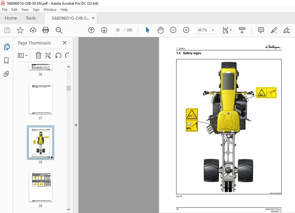
1 4 Safety signs 38
1 4 1 Overhead electrical power lines 39
1 4 2 Starter bypass 39
1 5 Cab safety signs 4 0
1 5 1 Operator’s manual 4 1
1 5 2 Park brake 4 1
Applicator Chassis
568096O1G
Table of contents
1 5 3 Bystander alert 4 1
1 5 4 Crushing hazard 4 1
1 5 5 Fall off hazard 4 2
1 5 6 Seatbelt 4 2
1 5 7 No passengers 4 2
1 6 Chassis safety signs 43
1 6 1 Hot pressurized coolant 4 4
1 6 2 Rotating blades 4 4
1 6 3 High pressurized fluid 4 5
1 6 4 Ether 4 5
1 6 5 Belt entanglement 4 6
1 6 6 Electrocution hazard 4 6
1 6 7 Radar 4 6
1 6 8 Crushing hazard 4 7
1 7 Informational signs 48
1 7 1 Informational – Tiedown 4 9
1 7 2 Ultra low sulfur diesel fuel 4 9
1 7 3 Informational – Cab filter #1 4 9
1 7 4 Informational – Hand wash 4 9
1 7 5 Informational – Battery terminals 5 0
1 7 6 Informational – Cab filter #3 5 0
1 7 7 Informational – Cab filter #2 and washer bottle 5 0
1 7 8 Informational – Manufacturer plate 5 0
1 7 9 Informational -Alternate exit 5 1
1 7 10 Informational – Outlet voltage and maximum amperage 5 1
1 7 1 1 Informational – Hydraulic oil level 5 1
1 8 Informational electrical signs 52
1 8 1 Informational – Power distribution module 5 2
1 8 2 Informational – Upper electrical panel 5 3
1 8 3 Informational – Lower electrical panel 5 4
1 8 4 Informational – Chassis electrical panel 5 5
2 Introduction 57
2 1 Information 59
2 1 1 Intended use 5 9
2 1 2 Proper disposal of waste 5 9
2 1 3 Emissions reduction – selective catalyst reduction – SCR – technology 5 9
2 1 4 DEF Storage and Shelf Life 6 0
2 2 Machine identification 62
2 2 1 Product identification information 6 2
2 2 2 Serial number definition 6 2
2 2 3 Engine serial number plate 6 3
2 2 4 Transmission serial number plate 6 4
2 3 Break-in period 65
2 3 1 General break-in information 6 5
2 3 2 Breaking-in maintenance schedule 6 5
2 3 3 Operating the engine-first 2 00 hours 6 5
2 3 4 Initial interval for inline fuel strainer 6 5
2 3 5 Breaking-in the transmission 6 5
2 3 6 Break-in the rear axle 6 5
2 3 7 Checking the wheel mounting hardware 6 5
2 3 8 Hydraulic filter 6 6
2 3 9 Initial pressure washer pump 6 6
2 4 Machine transport 67
2 4 1 Operating the machine in limp-home mode 6 7
2 4 2 Transporting the machine on a truck or trailer 7 0
2 4 3 Towing information 7 1
Applicator Chassis
568096O1G
Table of contents
2 4 3 1 Preparing for towing – engine operating 7 1
2 4 3 2 Preparing for towing – engine not operating 7 4
2 4 3 3 Towing procedure 7 4
2 5 Park brake information 76
2 5 1 Releasing the manual park brake 7 6
2 5 2 Releasing the park brake using air 7 6
2 5 3 Releasing the park brake by manually releasing the spring 7 6
2 6 Major components 79
2 6 1 Component location (front/rear view) 7 9
2 6 2 Component location (side view) 8 0
2 6 3 Component location (top view) 8 1
2 7 Emissions warranty 82
2 7 1 United States and Canada emission control warranty statement 8 2
2 7 2 California emission control warranty statement 8 5
3 Operation 89
3 1 Cab temperature control 91
3 1 1 Automatic temperature control 9 1
3 1 2 Heater operation 9 2
3 1 3 Defroster operation 9 2
3 1 4 Air conditioner operation 9 2
3 1 5 Automatic fan speed control 9 3
3 1 6 Manual fan speed control (HI/LO) 9 3
3 1 7 Air conditioning compressor clutch control 9 3
3 1 8 Heater water valve 9 3
3 1 9 Cab air temperature sensor 9 3
3 1 10 Evaporator probe 9 4
3 1 11 Temperature control troubleshooting 9 4
3 2 Controls and instruments 96
3 2 1 Inside cab components 9 6
3 2 2 Light switches for machine lights 9 8
3 2 3 Seatbelt operation 9 9
3 2 4 Basic operator seat 100
3 2 5 Deluxe operator seat 101
3 2 6 Deluxe vented operator seat 102
3 2 7 Instructor seat 103
3 2 8 Armrest controls 104
3 2 9 Joystick controls 105
3 2 10 Instrument cluster 105
3 2 11 Steering wheel controls 110
3 2 11 1 Power shuttle and shuttle lock 111
3 2 11 2 Shuttle shifting 112
3 2 12 Park brake 112
3 2 13 Foot pedals 112
3 2 14 Telemetry (if equipped) 113
3 2 15 Monitor/Camera (if equipped) 114
3 2 16 Battery disconnect switch 114
3 2 17 DOT matrix display screens 115
3 2 18 DOT matrix display screen operation 118
3 2 19 Changing speed readout units 12 3
3 2 2 0 Resetting the maintenance indicator lamp and the service hourmeter 12 4
3 2 2 1 Application rate controller options 12 4
3 2 2 2 Slingshot ready – if equipped 12 5
3 3 Tag axle operation 126
3 3 1 Tag axle 12 6
3 3 2 Operating the tag axle 12 6
3 4 Preparing to start the engine 127
Applicator Chassis
568096O1G
Table of contents
3 4 1 Checking the engine before starting 12 7
3 4 2 Engine power limitations 12 7
3 4 3 Low DEF level 12 8
3 4 4 SC R system malfunction 12 9
3 4 5 Starting the engine 13 0
3 4 6 Cold temperature starting 13 2
3 4 7 Stalled engine – restart 13 2
3 4 8 Stopping the engine and afterrun 13 3
3 4 9 Using the engine throttle control switches 13 3
3 4 9 1 Remote throttle preset 13 3
3 4 9 2 Location of the remote throttle control 13 3
3 4 9 3 Remote throttle controls 13 3
3 5 Operating on a public road 135
3 5 1 Machine operation on a public road 13 5
3 6 Transmission function 136
3 6 1 Transmission – general 13 6
3 6 2 High and low speed range 13 6
3 6 3 Setting the preset start up speeds 13 7
3 6 4 Engine underspeed supervisor 13 8
3 6 5 Joystick mode 13 9
3 6 6 Foot pedal throttle mode 14 0
3 6 7 Machine management system 14 0
3 7 Calibration 142
3 7 1 Machine calibration 14 2
3 7 2 Inputting at level 1 – Cal 2 14 2
3 7 3 Clearing the DCC 3 dash cluster error code 14 3
3 7 4 Calibrating the joystick handle 14 4
3 7 5 Calibrating the clutch 14 4
3 7 6 Calibrating the foot pedal throttle 14 5
3 7 7 Clearing the Auto 4 transmission controller error code 14 6
3 7 8 Inputting at level 1 – Cal 1 14 7
3 7 9 Calibrating the hare and tortoise range 14 7
3 7 10 Calibrating the transmission 14 8
3 7 11 Calibrating the coupler function 14 9
3 7 12 Calibrating the radar 15 0
3 7 13 Calibrating the speed 15 1
3 8 Cold weather considerations 152
3 8 1 Minimizing the effect of cold weather 15 2
3 8 2 Using grade No 1-D fuel 15 2
3 8 3 Fuel filters 15 2
3 8 4 Coolant heater 15 2
3 8 5 Seasonal viscosity oil and proper coolant concentration 15 2
3 8 6 Winterfronts 15 2
3 8 7 Idling the engine 15 3
3 8 8 Engine coolant specifications 15 3
3 8 9 Cooling system water quality 15 3
3 8 10 Antifreeze 15 3
3 8 11 Grease 15 4
3 8 12 Diesel fuel 15 4
3 8 13 Lubricity of diesel fuels 15 4
3 8 14 Storing the diesel fuel 15 5
3 9 Storage 156
3 9 1 Preparing for long term storage 15 6
3 9 2 Removing the machine from long term storage 15 6
4 Maintenance 159
4 1 Maintenance intervals 163
Applicator Chassis
568096O1G
Table of contents
4 1 1 Maintenance introduction 1 6 3
4 1 2 Maintenance symbols 16 3
4 1 3 Lubricant filling reminders 1 6 4
4 1 4 Maintenance schedule 16 4
4 1 4 1 Maintenance chart for Jackson 16 4
4 1 4 2 Daily maintenance schedule 16 6
4 1 4 3 Maintenance schedule 10 to 1000 hours 16 7
4 1 4 4 Maintenance Schedule 2000 to 4 000 hours 16 9
4 1 5 Lubricants and fluids 1 6 9
4 2 Air dryer and compressed air system 171
4 2 1 Air reservoir and air dryer 1 7 1
4 2 2 Replacing the air dryer filter 1 7 1
4 3 Air conditioner system 17 3
4 3 1 Air conditioner 1 7 3
4 3 2 Condenser 1 7 3
4 4 Engine 174
4 4 1 Checking the engine oil level 1 7 4
4 4 2 Changing the engine oil and filter 1 7 5
4 4 3 Engine belts and tensioner 1 7 5
4 4 3 1 Replacing the serpentine belt 1 7 5
4 4 3 2 Replacing the water pump belt 1 7 6
4 4 4 Fuel system 1 7 8
4 4 5 Fuel tank 1 7 8
4 4 6 In-line fuel strainer 1 7 9
4 4 7 Replacing the fuel filters 1 7 9
4 4 8 Priming the fuel system 1 8 0
4 4 9 Engine coolant 1 8 1
4 4 10 How to recognize an engine with hydraulic lash adjusters 1 8 2
4 5 Maintaining the air cleaner 184
4 5 1 Engine air cleaner indicator 1 8 4
4 5 2 Replacing the air filter element 1 8 4
4 5 3 Secondary air filter element 1 8 5
4 6 Hydraulic system 186
4 6 1 Do a hydraulic oil-level check 1 8 6
4 6 2 Replace the hydraulic system fluid and filter 1 8 6
4 7 Continuously variable transmission 188
4 7 1 Transmission operating temperatures and fluid change intervals 1 8 8
4 7 2 Checking the transmission oil 1 8 8
4 7 3 Change the transmission oil 1 8 9
4 8 Lubricating the driveline and inspecting the U-joint 191
4 8 1 Inspecting and lubricating the engine to transmission driveline 1 91
4 8 2 Lubricating the transmission to rear axle driveline 1 92
4 9 lntercoolers 193
4 9 1 Heat exchangers 1 93
4 9 2 Cleaning the heat exchangers 1 93
4 10 Wheel and axle bearings 195
4 10 1 Lubricating the front wheel bearing 1 95
4 10 2 Tag axle bearing bolts and lubricating the tag axle fittings – if equipped 1 95
4 11 Steering 196
4 1 1 1 Steering cylinder 1 96
4 12 Rear axle 197
4 1 2 1 Cleaning the breather for the rear axle 1 97
4 1 2 2 Do a check of the rear axle oil 1 97
4 1 2 3 Break-in the rear axle 1 98
4 1 2 4 Change the rear axle oil 1 98
4 13 Brake maintenance 200
Applicator Chassis
568096O1G
Table of contents
4 1 3 1 Lubricating the brake slack adjuster 2 00
4 1 3 2 Brake air lines 2 00
4 1 3 3 Park brake 2 00
4 13 4 Checking the service brake system 2 00
4 1 3 5 Checking the automatic slack adjusters 2 01
4 1 3 6 Manually adjusting the automatic slack adjusters 2 02
4 14 Wheels 203
4 14 1 Removing the front wheel 2 03
4 14 2 Installing the front wheel 2 04
4 14 3 Removing the rear wheel 2 06
4 14 4 Installing the rear wheel 2 07
4 14 5 Tightening the wheel mounting hardware 2 07
4 15 Tires 208
4 1 5 1 Inflating the tire 2 08
4 1 5 2 Replacing the tire 2 08
4 1 5 3 Tire charts 2 08
4 16 Cabin filters and windscreen wipers 211
4 16 1 Cab air filters and the windscreen washer reservoir 2 1 1
4 1 6 2 Maintaining the cab air filter 2 1 1
4 16 2 1 Maintaining the primary fresh air filte r 211
4 1 6 2 2 Maintaining the secondary fresh air filter 2 1 1
4 16 2 3 Maintaining the recirculation air filter 2 1 2
4 16 2 4 Cleaning the cab filter element 2 1 2
4 16 3 Cab air filters 2 1 2
4 16 3 1 Removing the primary fresh air filter 2 1 2
4 16 3 2 Installing the primary fresh air filter 2 1 3
4 16 3 3 Removing the secondary fresh air filter 2 1 3
4 16 3 4 Installing the secondary fresh air filter 2 1 5
4 16 3 5 Removing the recirculation air filter 2 1 5
4 16 3 6 Installing the recirculation air filter 2 1 7
4 16 4 Windscreen wiper blade 2 1 7
4 16 5 Filling the windscreen washer reservoir 2 1 7
4 17 Cab mounts 218
4 1 7 1 Checking the cab mounting bolts, rubber mounts, and air ride suspension 2 1 8
4 1 7 2 Checking the cab mounting bolts and rubber mounts 2 1 8
4 18 Electrical system 219
4 1 8 1 Batteries 2 1 9
4 1 8 1 1 Battery box components 2 1 9
4 18 1 2 Battery disconnect switch lever 220
4 1 8 1 3 Removing the battery terminal connection 2 2 1
4 1 8 2 Jump starting the battery 2 2 1
4 1 8 3 Locating the fuse panel 2 2 2
4 1 8 4 Fuse locations 2 2 3
4 19 Cab seat preventative maintenance 226
4 19 1 Lubricating the seat adjusters 2 2 6
4 19 2 Armrest mechanism 2 2 6
4 20 Paint and decals 227
4 2 0 1 Safety treads 2 2 7
4 21 Hand rinse tank and pressure washer 228
4 2 1 1 Removing the hand rinse tank 2 2 8
4 2 1 2 Installing the hand rinse tank 2 2 8
4 2 1 3 Pressure washer 2 2 8
4 2 1 3 1 Pressure washer input water supply 2 2 8
4 2 1 3 2 Before starting the pressure washer 2 2 9
4 2 1 3 3 Priming the pressure washer pump 2 2 9
4 2 1 3 4 General care of the pressure washer pump 2 2 9
4 2 1 3 5 Pressure washer pump storage in freezing conditions 2 2 9
Applicator Chassis
568096O1G
Table of contents
4 2 1 3 6 Operating the pressure washer 2 2 9
4 2 1 3 7 Changing the pressure washer pump motor oil 2 3 0
4 2 1 3 8 Changing the pressure washer strainer 2 3 0
4 2 1 3 9 Winterizing the pressure washer system 2 3 1
4 2 1 3 10 During system changeovers 2 3 1
4 22 Application system 232
4 2 2 1 System installation 2 3 2
5 Troubleshooting 233
5 1 Engine 235
5 1 1 Low diesel exhaust fluid (DEF)/AdBlue® level 2 3 9
5 2 Transmission 240
5 3 Electrical system 242
5 4 Hydraulic system 243
5 5 Parking brake troubleshooting 244
5 6 Operation 245
5 7 Cab 246
5 8 Fault codes 247
5 8 1 Engine control system error and fault codes 2 4 7
5 8 2 Transmission error and fault codes 2 6 3
5 8 3 DCC3 error and fault codes 2 6 6
5 8 4 Chassis error and fault codes 2 6 7
6 Specifications 273
6 1 Machine specifications 275
6 2 Machine dimensions 278
7 Index 283
CHALLENGER EU APPLICATOR TG7300B TG8300B CHASSIS OPERATOR’S MANUAL – PDF DOWNLOAD:
IMAGES PREVIEW OF THE MANUAL:


PLEASE NOTE:
- This is the same manual used by the dealers to diagnose and troubleshoot your vehicle
- You will be directed to the download page as soon as the purchase is completed. The whole payment and downloading process will take anywhere between 2-5 minutes
- Need any other service / repair / parts manual, please feel free to contact [email protected] . We still have 50,000 manuals unlisted
S.V