
Challenger EU Applicators 1800 2400 Gallons Flotation System Operator’s Manual
Original price was: $98.95.$23.95Current price is: $23.95.
Challenger EU Applicators 1800 2400 Gallons Flotation System Operator’s Manual – PDF DOWNLOAD
Description
Challenger EU Applicators 1800 2400 Gallons Flotation System Operator’s Manual – PDF DOWNLOAD
CHALLENGER EU APPLICATORS 1800 2400 GALLONS FLOTATION SYSTEM OPERATOR’S MANUAL:
IMAGES PREVIEW OF THE MANUAL:


FILE DETAILS:
Challenger EU Applicators 1800 2400 Gallons Flotation System Operator’s Manual – PDF DOWNLOAD
Size: 35.6 MB
Format: PDF
Language: English
Brand: Challenger
Type of Machine: Applicators
Type of document: Operator’s Manual
Model: Challenger EU Application System 1800 2400 Gallons Flotation System
Serial Number: EFF…Kxxx1001
Number of Pages: 250 pages
Date Modified: 09/2019
Part Number: 603483D1C
DESCRIPTION:
Challenger EU Applicators 1800 2400 Gallons Flotation System Operator’s Manual – PDF DOWNLOAD
Prepare for operation:
Read and understand all operation instructions and precautions in this manual before you operate the machine or do the servicing. Make sure that you know and understand the positions and operations of all controls. Make sure that all controls are in neutral and that the parking brake is applied before you start the machine. Make sure that all persons are away from your area of work before you start and operate the machine.
- Examine and learn the controls in an area that is clear of persons and obstacles before you start work. Know the machine dimensions and make sure that you have sufficient space available to operate the machine.
- Do not operate the machine at high speeds in crowded areas. It is important to know and use the correct procedures when you do work around and operate the machine. Do not let children or unqualified persons operate the machine.
- Keep others, especially children, away from your area of work. Do not let others ride on the machine. Make sure that the machine is in good condition for operation. Refer to the operator manual. Make sure that the machine has the correct equipment required by local regulations
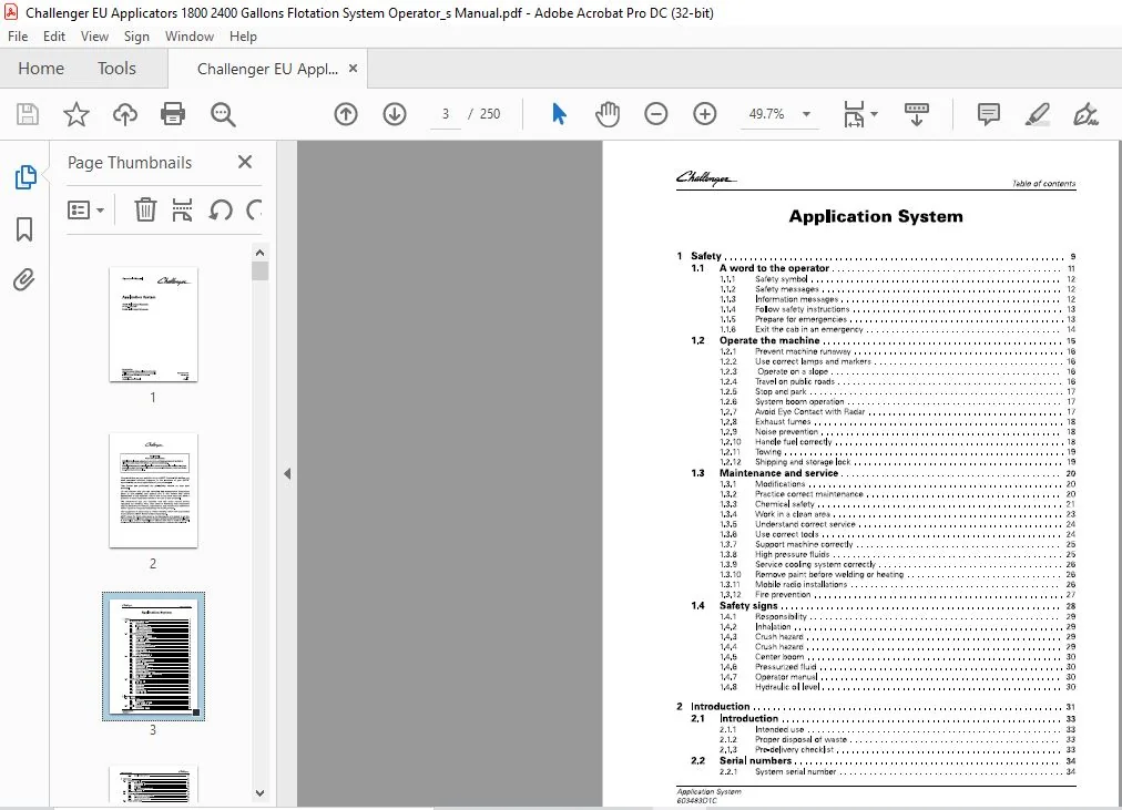
TABLE OF CONTENTS:
Challenger EU Applicators 1800 2400 Gallons Flotation System Operator’s Manual – PDF DOWNLOAD
1 Safety 9
1 1 A word to the operator 11
1 1 1 Safety symbol 1 2
1 1 2 Safety messages 1 2
1 1 3 Information messages 1 2
1 1 4 Follow safety instructions 1 3
1 1 5 Prepare for emergencies 1 3
1 1 6 Exit the cab in an emergency 1 4
1 2 Operate the machine 15
1 2 1 Prevent machine runaway 16
1 2 2 Use correct lamps and markers 16
1 2 3 Operate on a slope 16
1 2 4 Travel on public roads 16
1 2 5 Stop and park 17
1 2 6 System boom operation 17
1 2 7 Avoid Eye Contact with Radar 17
1 2 8 Exhaust fumes 1 8
1 2 9 Noise prevention 1 8
1 2 10 Handle fuel correctly 1 8
1 2 1 1 Towing 19
1 2 1 2 Shipping and storage lock 19
1 3 Maintenance and service 20
1 3 1 Modifications 20
1 3 2 Practice correct maintenance 20
1 3 3 Chemical safety 2 1
1 3 4 Work in a clean area 2 3
1 3 5 Understand correct service 2 4
1 3 6 Use correct tools 2 4
1 3 7 Support machine correctly 2 5
1 3 8 High pressure fluids 2 5
1 3 9 Service cooling system correctly 26
1 3 10 Remove paint before welding or heating 26
1 3 1 1 Mobile radio installations 26
1 3 1 2 Fire prevention 27
1 4 Safety signs 28
1 4 1 Responsibility 29
1 4 2 Inhalation 29
1 4 3 Crush hazard 29
1 4 4 Crush hazard 29
1 4 5 Center boom 30
1 4 6 Pressurized fluid 30
1 4 7 Operator manual 30
1 4 8 Hydraulic oil level 30
2 Introduction 31
2 1 Introduction 33
2 1 1 Intended use 3 3
2 1 2 Proper disposal of waste 3 3
2 1 3 Pre-delivery checklist 3 3
2 2 Serial numbers 34
2 2 1 System serial number 3 4
Application System
603483O1C
Table of contents
2 2 2 Serial number definition 3 4
3 Operation 35
3 1 System controls 39
3 1 1 Drive lever controls 3 9
3 1 2 Armrest controls 3 9
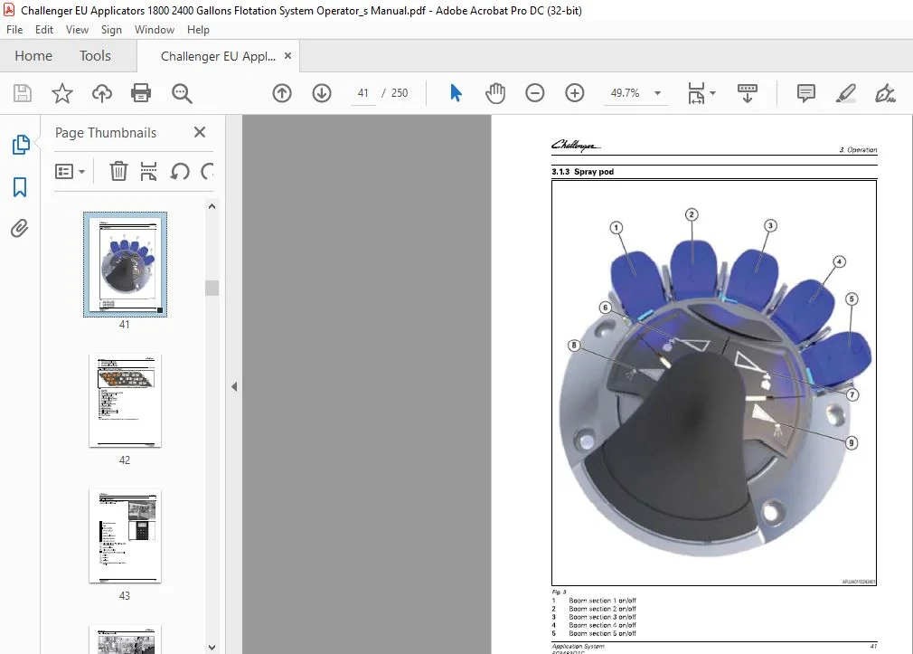
3 1 3 Spray pod 4 1
3 1 4 Multifunction armrest keypad 4 2
3 1 5 Reload keypad 4 3
3 2 Plumbing controls 44
3 3 Foam marker 46
3 3 1 View the foam marker settings 4 6
3 3 2 Fill the foam marker tank 4 6
3 3 3 Operate the foam marker 4 7
3 4 Fresh water tank 49
3 4 1 Fill the fresh water tank 4 9
3 5 Product tank 50
3 5 1 Fill the product tank with an external pump 5 0
3 5 2 Fill the product tank with the on board pump 5 1
3 5 3 Operate the eductor 5 4
3 6 Product pump 58
3 7 Hydraulic system 59
3 8 Manual throttle valve 60
3 9 Factors for application 61
3 9 1 Nozzle selection 61
3 9 2 End row nozzles 61
3 9 3 Boom sections 61
3 10 Raven Viper 4 values 62
3 11 TaskDoc TM / TaskDoc Pro TM overview 64
3 11 1 TaskDoc system overview 64
3 11 2 TaskDoc Pro system overview 64
3 12 TaskDoc TM menu overview 66
3 1 2 1 TaskDoc menu overview 66
3 13 TaskDoc™ / TaskDoc Pro™ commissioning 67
3 13 1 Install the mini SIM card for Global System for Mobile communication (GSM) 67
3 13 2 Condition for the commissioning 68
3 13 2 1 Switch on ISOBUS 68
3 13 3 Connection settings 69
3 13 3 1 View/adjust the connection settings for the Global Systems for
Mobile Communications (GSM) network 69
3 13 4 View the connection settings for the Code Division Multiple Access (CDMA)/
Long Term Evolution (LTE) network 72
3 13 5 View/adjust the connection settings for the Global Systems for Mobile
Communications (GSM) network 73
3 14 TaskDoc™ operation and settings 77
3 14 1 TaskDoc information 77
3 14 2 View the TaskDoc™ main menu 78
3 14 3 Make a task 78
3 14 4 Copy a task/create a task template 80
3 14 5 Select a task 81
3 14 6 Add categories to a task 82
3 14 7 Delete categories from a task 83
3 14 8 Filter by categories 84
3 14 9 View the TaskDoc™ data settings 85
3 14 10 View the roaming settings 86
3 1 4 1 1 View the on-board computer 87
3 1 4 1 2 Memory space monitoring 89
3 1 4 1 3 Delete all TaskDoc data 89
TaskDoc TM faults and remedy 91
3 1 5 1 System test 9 1
3 1 5 1 1 Starting the system test 9 1
3 1 5 1 2 System test results 9 1
Auto-Guide TM
3 1 6 1 View the Auto-Guide™ map 9 4
3 1 6 2 View the worked area settings 9 5
3 16 3 View the Auto-Guide™ main menu 9 6
3 1 6 4 View the field settings 97
3 1 6 4 1 Add a boundary 98
View the implement selection 1 02
View the steering settings 1 03
View the signal settings 1 04
View the correction signal screen 1 04
3 1 6 8 1 Select the signal type 1 05
3 1 6 9 View the system screen 1 07
3 1 6 1 0 View the NMEA settings 1 08
3 1 6 1 1 View the headland settings 1 09
3 1 6 1 2 Select the Auto-Guide™ button 1 09
AgControl™ Section Control operation and configuration 111
3 1 7 1 AgControl™ Section Control description 1 1 1
3 1 7 2 Section Control overview menu 1 1 1
3 1 7 3 AgControl™ icons 1 1 2
3 1 7 4 View the AgControl™ menus 1 1 3
3 17 5 View the rate control settings 1 1 4
3 1 7 6 View the virtual switch box 1 1 5
3 1 7 7 View the product flow 1 1 6
3 1 7 8 View the nozzle settings 1 1 6
3 1 7 9 View the boom settings 1 17
3 1 7 1 0 View the life time totals 1 18
3 1 7 1 1 Error codes 1 18
3 1 7 1 1 1 View the active error codes 1 18
3 1 7 1 1 2 View the stored error codes 1 19
3 1 7 1 2 View the Software Information screen 1 20
Section control 121
3 18 1 View the section control switches 1 21
3 18 2 Select manual or automatic section control 1 21
3 18 3 Adjust the switch off time for section control 1 21
3 18 4 Adjust the switch on time for section control 1 23
3 18 5 Automatic Section Control 1 24
3 18 6 View the section control settings 1 25
3 18 7 View the section settings 1 26
AgControl™ Variable Rate Control (VRC) operation and settings 127
3 19 1 AgControl Variable Rate Control (VRC) System requirements 1 27
3 19 2 View the TaskDoc™ data settings 1 27
3 19 3 AgControl Variable Rate Control (VRC) make an application map with a field
database 1 28
3 19 4 AgControl Variable Rate Control (VRC) TaskDoc requirements 1 29
3 19 5 Activate the AgControl Variable Rate Control (VRC) 1 3 0
3 19 6 AgControl Variable Rate Control (VRC) Pause task 1 3 2
3 19 7 AgControl Variable Rate Control (VRC) map view and layer selection 1 3 3
3 19 8 AgControl Variable Rate Control (VRC) example map views 1 3 4
TaskDoc™ quick start guides 136
3 20 1 Start a task from scratch 1 3 6
Application System
603483O1C
Table of contents
3 20 1 1 Add a boundary (optional) 1 4 1
3 20 1 2 Save task to USB 1 4 5
3 20 1 3 Save task by wireless transfer 1 4 7
3 20 2 Use a task uploaded from a USB 1 4 7
3 20 2 1 Add a boundary (optional) 1 5 2
3 20 3 Use a task uploaded Wirelessly 1 5 8
3 20 3 1 Add a boundary 1 6 2
3 21 Management 168
3 21 1 Machine administration, implement administration and field administration; data
exchange 1 6 8
3 21 1 1 Data exchange with a USB stick 1 6 8
3 22 System calibration 170
3 22 1 Calibrate the automatic fold 170
3 22 2 Calibrate the pump and nozzle pressure transducer 171
3 22 3 Calibrate the nozzles 172
3 22 4 Calibrate the tank level sensor 173
3 22 5 Calibrate the controller 173
3 23 Apply product 175
3 24 Cleaning procedures 17 9
3 24 1 Boom CleanOut 179
3 24 2 Boom product recovery 18 0
3 24 3 Release the line pressure from the booms 18 3
3 24 4 Drain the product tank 18 3
3 24 4 1 Drain the product tank with the pump off port 18 5
3 24 5 Flush the system using the top tank 187
3 24 6 Prepare the machine at the end of the job 19 0
3 25 Spray control calculator 193
3 25 1 Determine the application rates and nozzles 19 3
3 25 2 Determine the speed range 19 4
3 25 3 Other uses for the spray control calculator 19 6
4 Maintenance 197
4 1 Machine maintenance 199
4 1 1 Maintenance schedule 19 9
4 1 2 Weld on the machine 19 9
4 1 3 Lubricant filling reminders 200
4 1 4 Hydraulic system oil 200
4 1 5 Hydraulic system components 200
4 1 6 Change the hydraulic oil 201
4 2 General maintenance 203
4 2 1 Clean the liquid system 203
4 2 2 Strainer 203
4 2 3 Hoses 203
4 2 4 Winterize the liquid system 203
4 2 5 Winterize the foam marker 205
4 3 Boom maintenance 206
4 3 1 Lubricate the boom tree 206
4 3 2 Lubricate the boom fold 206
4 4 System 208
4 4 1 Remove the liquid system 208
4 4 1 1 18 0 0 gal liquid system 208
4 4 1 2 24 0 0 gal liquid system 21 4
4 4 1 3 Remove the 4 x 3 plumbing and hydraulic pump 21 5
4 4 1 4 Remove the 5 x 3 plumbing and hydraulic pump 219
4 4 2 Install the liquid system 224
4 4 2 1 18 0 0 gal liquid system 224
Table of contents
2 4 0 0 gal liquid system 2 3 1
Install the 4 x 3 plumbing and hydraulic pump 2 3 3
Install the 5x 3 plumbing and hydraulic pump 2 3 6
5 Specifications 241
5 1 System specifications 243
5 1 1 Product tank 2 4 3
5 1 2 Rinse tank 2 4 3
5 1 3 Chemical eductor 2 4 3
6 Index 245
Application System
PLEASE NOTE:
- This is the SAME manual used by the dealers to troubleshoot any faults in your vehicle. This can be yours in 2 minutes after the payment is made.
- Contact us at [email protected] should you have any queries before your purchase or that you need any other service / repair / parts operators manual.
S.V