
Challenger EU Applicators RG1100C RG1300C RoGator Chassis Tier 3 Operator’s Manual
Original price was: $98.95.$25.95Current price is: $25.95.
Challenger EU Applicators RG1100C RG1300C RoGator Chassis Tier 3 Operator’s Manual – PDF DOWNLOAD
Description
Challenger EU Applicators RG1100C RG1300C RoGator Chassis Tier 3 Operator’s Manual – PDF DOWNLOAD
IMAGES PREVIEW OF THE MANUAL:


FILE DETAILS:
Challenger EU Applicators RG1100C RG1300C RoGator Chassis Tier 3 Operator’s Manual – PDF DOWNLOAD
Size: 57.4 MB
Format: PDF
Language: English
Brand: Challenger
Type of Machine: Applicators
Type of document: Operator’s Manual
Model: Challenger EU RoGator RG1100C RG1300C Chassis Tier 3
Number of Pages: 452 pages
Serial Number: AGCCXX00XJXXX1001-
Part Number: 581294D1C
Date Modified: 04/2018
DESCRIPTION:
Challenger EU Applicators RG1100C RG1300C RoGator Chassis Tier 3 Operator’s Manual – PDF DOWNLOAD
Important safety information :
Most accidents that involve product operation, maintenance and repair are caused by failure to observe basic safety rules or precautions. An accident can often be avoided by recognizing potentially hazardous situations before an accident occurs. A person must be alert to potential hazards. This person must also have the necessary training, skills and tools to do these functions correctly. Incorrect operation, lubrication, maintenance, or repair of this product can be dangerous and can result in injury or death.
- Do not operate or do any lubrication, maintenance or repair on this product, until you read and understand the operation, lubrication, maintenance, and repair information. Safety precautions and warnings are provided in this manual and on the product. If these hazard warnings are not heeded, bodily injury or death can occur to you or other persons. AGCO cannot anticipate every possible circumstance that might involve a potential hazard.
- The warnings in this publication and on the product are, thus, not all-inclusive. If a tool, procedure, work method or operating technique that is not specifically recommended by AGCO is used, you must satisfy yourself that it is safe for you and others. You must make sure the product will not be damaged or made unsafe by the operation, lubrication, maintenance, or repair procedures that you choose.
- The information, specifications, and illustrations in this publication are based on the information that was available at the time that the publication was written. The specifications, torques, pressures, measurements, adjustments, illustrations, and other items can change at any time. These changes can affect the service that is given to the product. Obtain the complete and most current information before you start any job. AGCO dealers have the most current information available.
A word to the operator:
It is your responsibility to read and understand the safety section in this manual and the manual for all implements before you operate this machine. You are responsible for your safety. Good safety procedures prevent injury to you and the persons around you. Make the information in the safety section of this manual a part of your safety procedure. This safety section is written only for this type of machine. Safety is your responsibility. You can prevent injury and death.
- This safety section gives basic safety examples that can occur during the operation and maintenance of your machine. This safety section is not a replacement for safety instruction in other sections of this manual.
- Injury or death can occur if the safety instruction is not obeyed. Learn how to operate the machine and how to use the controls correctly. Do not operate the machine if you do not know how to operate the machine.
- Do not let persons operate the machine that do not know how to operate the machine. Follow all safety instructions in the manuals and on the safety signs on the machine, the implements, and the attachments. Use only approved attachments and implements. Make sure that your machine has the correct equipment that is necessary by the local regulations.
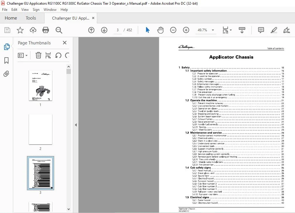
TABLE OF CONTENTS:
Challenger EU Applicators RG1100C RG1300C RoGator Chassis Tier 3 Operator’s Manual – PDF DOWNLOAD
1 Safety 13
1 1 Important safety information 15
1 1 1 Prepare for operation 1 5
1 1 2 A word to the operator 16
1 1 3 Safety symbol 17
1 1 4 Safety messages 17
1 1 5 Information messages 17
1 1 6 Follow safety instructions 1 8
1 1 7 Prepare for emergencies 1 8
1 1 8 Fire prevention 1 9
1 1 9 Prevent static discharge when fueling 1 9
1 1 10 Exit the cab in an emergency 1 9
1 2 Operate the machine 21
1 2 1 Prevent machine runaway 2 2
1 2 2 Use correct lamps and markers 2 2
1 2 3 Operation on slopes 2 2
1 2 4 Travel on public roads 2 3
1 2 5 Stopping and parking 2 3
1 2 6 System boom operation 2 3
1 2 7 Exhaust fumes 2 4
1 2 8 Noise prevention 2 4
1 2 9 Handle fuel correctly 2 4
1 2 10 Towing 2 5
1 2 1 1 Modifications 2 5
1 3 Maintenance and service 26
1 3 1 Practice correct maintenance 26
1 3 2 Chemical safety 27
1 3 3 Work in a clean area 2 9
1 3 4 Understand correct service 30
1 3 5 Use correct tools 30
1 3 6 Support machine correctly 3 1
1 3 7 High pressure fluids 3 1
1 3 8 Service cooling system correctly 3 2
1 3 9 Remove paint before welding or heating 3 2
1 3 10 Tires and wheels 3 3
1 3 1 1 Mobile radio installations 3 3
1 3 1 2 Fire prevention 3 3
1 4 Cab safety signs 35
1 4 1 Read manual 36
1 4 2 Break glass – exit 36
1 4 3 Sound horn 36
1 4 4 Electrical hazard 36
1 4 5 Run-over hazard 37
1 4 6 Cab filter number 2 37
1 4 7 Cab filter number 3 37
1 4 8 Cab filter number 1 37
1 4 9 Roll over – wear seat belt 3 8
1 4 10 Run over – no riders 3 8
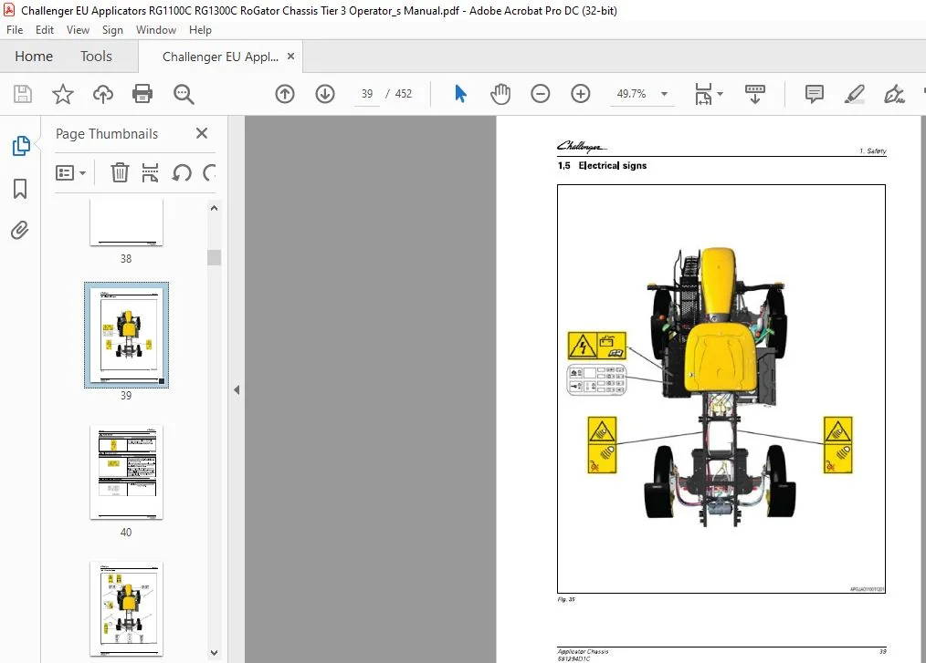
1 5 Electrical signs 39
1 5 1 Radar hazard 40
1 5 2 Electrocution hazard 40
Applicator Chassis
58129401C
Table of contents
1 5 3 Fuse/relay and battery sign 40
1 6 Chassis signs 41
1 6 1 Fall off hazard 42
1 6 2 Air dump 42
1 6 3 Roll over 42
1 6 4 Pinch hazard 42
1 6 5 T ie down 4 3
1 6 6 Lift point 4 3
1 6 7 Drain the air tank 4 3
1 6 8 Hand wash 4 3
1 6 9 Axle spacing left-hand 4 4
1 6 10 Axle spacing right-hand 4 4
1 7 Hydraulic signs 45
1 7 1 Explosion injury hazard 4 6
1 7 2 High pressure hazard 4 6
1 8 Engine signs 47
1 8 1 Separator filter 4 8
1 8 2 Fuel filter 4 8
1 8 3 Fuel water separator head 4 8
1 8 4 High pressure hazard 4 9
1 8 5 Entanglement 4 9
1 8 6 Entanglement 4 9
1 8 7 Run over hazard 5 0
1 8 8 Ether 5 0
1 8 9 Diesel exhaust fluid filter 5 0
1 8 10 Fuel filter 5 0
1 8 1 1 Burn hazard 5 1
2 Introduction 53
2 1 Introduction 55
2 1 1 Intended use 5 5
2 1 2 Proper disposal of waste 5 5
2 1 3 Pre-delivery checklist 5 5
2 2 Serial number identification 56
2 2 1 Serial number definition 5 7
2 3 Hydrostatic drive system 59
2 3 1 Hydrostatic drive system introduction 5 9
2 3 2 Drive lever 5 9
2 3 3 Hydraulic drive pump 6 0
2 3 4 Charge pump 6 0
2 3 5 Oil cooler 6 1
2 3 6 Hydraulic system oil filters 6 1
2 4 Component locations 63
2 5 Fuses and relays 65
2 5 1 Fuse/relay panel 6 5
2 5 2 Main fuses 72
2 5 3 Chassis harness fuses 72
2 5 4 Power distribution module 72
2 6 EC -Declaration of Conformity 75
3 Operation 77
3 1 Instruments and controls 81
3 1 1 Dash panel 8 1
3 1 2 Operating status displays 8 2
3 1 3 Multiple display screens 8 2
3 1 4 How to clear dash panel fault codes 8 3
Applicator Chassis
58129401C
Table of contents
3 1 5 Console keypad 85
3 1 6 Ignition switch 86
3 1 7 Multifunction lever 87
3 1 8 Set the windshield wiper delay 87
3 1 9 Tilt – telescoping lever 88
3 1 10 Brake pedal 88
3 1 1 1 Drive lever controls 89
3 1 1 2 Arm rest controls 90
3 1 1 3 Armrest adjustment 90
3 1 1 4 Chassis keypad 91
3 1 1 5 Automatic heated mirrors 91
3 1 1 6 Power mirror adjustment 91
3 1 17 Interior lamps 92
3 1 1 8 Radio (if equipped) 92
3 1 1 9 Sun Visor 93
3 1 20 Cup holders 93
3 1 2 1 Storage compartments 93
3 1 2 2 Power strip 94
3 1 23 Power ports 94
3 1 2 4 Cargo net 95
3 1 25 Lamp switches 95
3 1 2 6 Bluetooth microphone 96
3 1 27 Objects in the cab 96
3 1 28 Automatic battery disconnect 97
3 2 Temperature control 98
3 2 1 Heater operation 98
3 2 2 Defrost or defog operation 99
3 2 3 Air conditioner operation 99
3 2 4 Automatic fan speed control 99
3 2 5 Manual fan speed control 10 0
3 2 6 Heater water valve 10 0
3 2 7 Cab air temperature sensor 10 0
3 2 8 Pressurizer blower 10 0
3 2 9 Air vents 10 1
3 3 Seats 102
3 3 1 Heated and ventilated seats 10 2
3 3 2 Basic operator seat 10 2
3 3 3 Deluxe operator seat 10 4
3 3 4 Deluxe vented operator seat 10 6
3 3 5 Instructor seat 10 7
3 4 General inspection 109
3 4 1 Check fluids 10 9
3 4 2 Check for Condition and Cleanliness 10 9
3 4 3 Check hydraulics 10 9
3 4 4 Check fuel system 1 10
3 4 5 Check cab 1 10
3 4 6 Check mirrors 1 10
3 4 7 Check the Hoses 1 10
3 4 8 Check the Safety Signs 1 10
3 5 Terminal 112
3 5 1 Terminal introduction 1 1 2
3 5 2 Audible alarms and indicators 1 1 3
3 5 3 Display the software information 1 1 4
3 5 4 Set the language 1 1 5
3 5 5 Set the date and time 1 1 7
3 5 6 Set the audio level 1 1 7
3 5 7 Set the screen brightness 1 1 9
Applicator Chassis
58129401C
Table of contents
3 5 8 Switch between day and night mode 1 20
3 5 9 Call up the USB Data screen 1 2 1
3 5 10 Select and transfer individual data to the USB stick 1 2 2
3 5 1 1 Select and transfer all data to the USB stick 1 2 4
3 5 1 2 Select and transfer individual data from the USB stick 1 2 6
3 5 1 3 Select and transfer all data from the USB stick 1 28
3 5 1 4 Clean the terminal screen 1 30
3 5 1 5 Calibrate the touch screen 1 3 1
3 5 1 6 Do a touch test 1 3 2
3 5 17 Set up the camera application – if equipped 1 3 3
3 5 1 8 View the service interval screens 1 3 4
3 5 1 9 Program the user-defined service intervals 1 3 5
3 5 20 Calibrate the radar 1 3 7
3 5 21 Calibrate the wheel speed 1 3 8
3 5 22 Calibrate the wheel speed and radar 1 40
3 5 23 Calibrate the steering angle sensor 1 4 2
3 5 24 Calibrate the steering valve 1 4 7
3 5 25 Calibrate the lever 1 5 2
3 5 26 Calibrate the brake pedal 1 5 7
3 5 27 View the diagnostic screens 1 61
3 5 28 View the active errors screen 1 63
3 5 29 Set the power management values 1 64
3 5 30 Display the four wheel steer 1 65
3 5 3 1 Set the track width presets 1 67
3 5 3 2 View the fuel consumption screen 1 68
3 5 3 3 Call up the ISOBUS Information screen 170
3 5 3 4 Set the acceleration rate 171
3 5 3 5 Select a four wheel steering mode 172
3 5 3 6 View the Auto-Guide™ map 172
3 5 3 7 View the worked area settings 173
3 5 3 8 Make a wayline from the map 174
3 5 3 8 1 AB wayline 175
3 5 3 8 2 Contour wayline 175
3 5 3 8 3 A+ angle wayline 176
3 5 3 8 4 Pivot 176
3 5 3 9 Make a boundary from the map 177
3 5 40 Make an obstacle from the map 178
3 5 4 1 Update the terminal software 1 80
3 6 Break-in-period 1 82
3 6 1 Do a check of the hydraulic system 1 82
3 6 2 Do a check of the wheel drive gearboxes 1 82
3 6 3 Coolant level 1 82
3 6 4 Tighten the wheel mounting hardware 1 82
3 6 5 Do a check of the torque rods 1 83
3 6 6 Do a check of the batteries 1 83
3 6 7 Do a check of the axle shims 1 83
3 6 8 Change the pressure washer pump oil – if equipped 1 84
3 6 9 Inspect the engine belts 1 84
3 6 10 Replace the fuel filter and the fuel pre-filter 1 84
3 6 1 1 Chassis and cab modification 1 84
3 7 Start the engine 1 85
3 7 1 Cold weather start procedure 1 86
3 7 2 Cold weather starting procedure for hydrostatic system 1 88
3 7 3 Cold start option 1 88
3 7 4 Restart a stalled engine 1 89
3 7 5 Engine overspeed protection 1 89
3 7 6 Engine anti-stall protection 1 89
3 7 7 Engine power limitations 1 89
Applicator Chassis
58129401C
Table of contents
3 7 8 Low diesel exhaust fluid (D EF) level 1 90
3 7 9 Stop the engine and afterrun 1 91
3 8 Drive the machine 192
3 8 1 Drive modes 1 92
3 8 2 Increase the drive speed 1 93
3 8 3 Decrease the drive speed 1 94
3 8 4 Change the drive direction 1 95
3 8 5 Stop the machine 1 95
3 8 6 Traction control 1 96
3 8 7 Engine R P M Guidelines 1 96
3 8 8 Set the cruise control speeds 1 97
3 8 9 Set the drive handle aggressiveness 1 97
3 8 10 Transmission management system (T MS) 1 98
3 8 1 1 Set the power management values 1 98
3 8 1 2 Weight determined speed 1 99
3 8 1 3 Machine braking 200
3 8 1 4 Backup alarm 200
3 9 AccuField Command 201
3 9 1 Manual configuration 201
3 9 2 General function – AccuField Command 202
3 9 3 Functions and dependencies 202
3 9 4 Call up and activate AccuField Command 204
3 9 5 Joystick assignment 205
3 9 6 Record an operational sequence 206
3 9 7 Start an operational sequence 209
3 9 8 Configure an operational sequence manually 210
3 9 9 Step mode 21 1
3 10 GatorTrak 4 wheel steer modes 213
3 10 1 Off mode 21 3
3 10 2 2WS mode 21 3
3 10 3 Auto 4 W S mode 21 4
3 10 4 4 W S mode 21 4
3 10 5 Crab mode 21 5
3 10 6 Automatic engagement and disengagement 21 5
3 11 Track adjust 216
3 1 1 1 Adjustment of track width 21 6
3 1 1 2 Adjust the manual track width 21 6
3 1 1 3 Adjust the hydraulic track width 21 7
3 1 1 4 Set the automatic track width 21 8
3 12 Transporting the machine 220
3 1 2 1 Travel on public roads 220
3 1 2 2 Air dump valve 220
3 1 2 3 Trailer the machine 221
3 1 2 4 Load the machine 221
3 1 2 5 Unload the machine 223
3 1 2 6 Tow the machine 224
3 1 2 7 Release the park brake manually 225
3 1 2 8 Re-engage the park brake 227
3 13 Camera settings 22a
3 1 3 1 Camera options and connections 228
3 1 3 2 Position the camera image 229
3 1 3 3 Change cameras 23 1
3 1 3 4 Display the camera image while reversing 23 3
3 1 3 5 Change the camera to and from full-screen 23 4
3 1 3 6 Adjust the brightness 23 5
3 1 3 7 Adjust the contrast 23 5
3 1 3 8 Adjust the color saturation 23 6
Applicator Chassis
58129401C
Table of contents
3 14 Optional pressure washer 23 7
3 1 4 1 Input water supply 2 3 7
3 1 4 2 Prime the pump 2 3 7
3 1 4 3 Operate the pressure washer 2 3 8
3 15 Optional accessories 240
3 1 5 1 Slingshot – if equipped 2 40
3 1 5 2 Weather station – if equipped 2 40
3 1 5 3 Install the mini S I M card for Global System for Mobile communication (GS M) 2 4 1
3 16 Changing the system 24 4
3 1 6 1 Remove the liquid system 2 4 4
3 1 6 2 Install the spinner system 2 5 2
3 1 6 3 Install the AirMax 1 80 system 2 5 8
3 1 6 4 Remove the AirMax 1 80 system 2 61
3 1 6 5 Remove the spinner system 2 64
3 1 6 6 Install the liquid system 2 69
4 Engine Operation 28 1
4 1 Safety instructions 283
4 2 To the user 284
4 2 1 Engine type designations 2 84
4 2 2 Location of the engine serial number 2 85
4 2 3 Marking of the electronic control unit 2 86
4 3 Technical data 287
4 3 1 Principal dimensions and data 2 87
4 3 2 Fuel system 2 87
4 3 3 Lubrication system 2 87
4 3 4 Cooling system 2 87
4 4 Air control system 288
4 4 1 Turbocharging 2 89
4 4 2 2 stage turbocharging 2 89
4 4 3 Cooling of inlet air 2 89
4 4 4 Interstage charge air cooling 2 89
4 4 5 Throttle valve 2 89
4 4 6 Exhaust gas recirculation system 2 90
4 5 Fuel system 29 1
4 6 Engine control system 293
4 7 Lubrication system 294
4 7 1 Oil pressure regulating valve 2 95
4 7 2 Oil filter and oil cooler 2 95
4 7 3 Oil filter and oil cooler 2 96
4 8 Cooling system 297
4 8 1 Engine heater 2 97
4 9 Electrical system 298
4 10 SCR system 299
4 10 1 SCR system overview 2 99
4 10 2 SCR system components and their functions 300
4 11 Operation and driving 301
4 1 2 Daily pre-start check 302
4 13 Starting the engine 303
4 1 3 1 Break in the engine 30 3
4 14 Starting the engine in cold conditions 305
4 1 4 1 Warming up the engine 30 5
4 15 Start the engine with an auxiliary battery 306
4 16 Attention during operation 307
Applicator Chassis
58129401C
Table of contents
4 17 Stopping the engine 308
5 Maintenance 309
5 1 Maintenance introduction 31 3
5 1 1 Lubricants and fluids 3 1 3
5 1 2 Fuel quality requirements 3 1 3
5 1 3 Coolant quality requirements 3 1 5
5 1 4 Oil quality 3 1 5
5 1 5 Lubricant filling reminders 3 1 6
5 2 Maintenance schedule 31 7
5 3 Engine maintenance information 321
5 3 1 Maintenance chart 3 21
5 3 2 Maintenance to be made daily or at 10 hours intervals 3 22
5 3 2 1 Do a check for the engine oil level 3 22
5 3 2 2 Check coolant level 3 23
5 3 2 3 Check for leakages 3 23
5 3 3 Maintenance to be made weekly or at 100 hours interval 3 23
5 3 3 1 Clean cooling system (from outside) 3 23
5 3 3 2 Examining the condition of the belt 3 23
5 3 4 Maintenance to be made at 3 00 – 6 00 hours intervals 3 24
5 3 4 1 Change engine oil 3 24
5 3 4 2 Oil sump capacity 3 24
5 3 4 3 Change oil filter 3 25
5 3 4 4 Update the engine software 3 25
5 3 4 5 How to recognize an engine with hydraulic lash adjusters 3 26
5 3 5 Change fuel filters 3 26
5 3 6 Bleed the fuel system 3 27
5 3 7 Maintenance to be made at 4000 hours intervals 3 29
5 3 7 1 Check turbocharger play and check that the intercooler cell is clean 3 29
5 3 8 Maintenance to be made once a year 3 29
5 3 8 1 SCR system maintenance 3 29
5 3 8 2 Replace the main filter and the inlet filter of the supply module 3 3 0
5 3 9 Maintenance to be made every two years 3 3 1
5 3 9 1 Change coolant 3 3 1
5 3 10 Additional maintenance instructions 3 3 2
5 3 10 1 Before the cold season 3 3 2
5 3 10 2 T ightening torques 3 3 2
5 3 10 3 Coolant quality requirements 3 3 4
5 3 10 4 Fuel quality requirements 3 3 5
5 4 Support the machine 338
5 4 1 Lifting and jacking points 3 3 8
5 4 2 Release the air from the air suspension 3 3 9
5 4 3 Place the jacks 3 40
5 4 4 Jack up the machine 3 4 1
5 5 Chassis maintenance 343
5 5 1 Lubricate the axles 3 4 3
5 5 2 Torque rods 3 4 4
5 5 3 Do maintenance on the torque rods and hardware 3 4 5
5 5 4 Install the axle bolts 3 4 5
5 5 5 Anti-roll bar 3 4 6
5 5 6 Do a check and tighten the inner axle weldment 3 4 6
5 5 7 Adjust a crop deflector 3 4 7
5 6 Wheel drive gearbox 348
5 6 1 Maintenance information 3 4 8
5 6 2 Do a check of the gearbox oil level 3 4 8
5 6 3 Fill the gearbox oil 3 4 9
5 6 4 Drain and replace the oil 3 4 9
Applicator Chassis
58129401C
Table of contents
5 6 5 Do a check of the wheel drive gearbox mounting hardware 3 5 0
5 7 E n g i n e m a i ntena nce 351
5 7 1 Do a check of the engine coolant 3 5 1
5 7 2 Do a check of the engine oil 3 5 1
5 7 3 Change the engine oil and filter 3 5 2
5 7 4 Engine belts 3 5 3
5 7 5 Replace the main serpentine belt 3 5 3
5 7 6 Replace the belt for the air conditioner compressor and water pump 3 5 5
5 7 7 Inspect and change the air filters 3 5 6
5 7 8 Clean the cooling package 3 5 8
5 7 9 Change the engine coolant 3 5 9
5 8 Fuel system m a i ntenance 361
5 8 1 Check and tighten the fuel tank bolts 3 6 1
5 8 2 Fuel quality requirements 3 6 1
5 8 3 Fuel tank 3 6 3
5 8 4 Fill the fuel system 3 6 3
5 8 5 Fuel filtration system 3 6 5
5 8 6 Change the pre-filter and fuel filter 3 6 5
5 8 7 Drain the additional fuel/water separator – if equipped 3 6 7
5 8 8 Change the fuel water separator element – if equipped 3 6 7
5 8 9 Bleed the fuel system 3 6 8
5 8 10 Fuel storage 3 6 8
5 8 1 1 Remove sediment and water from the fuel tanks 3 6 8
5 9 Hyd ra u l ic system m a i ntenance 370
5 9 1 Hydraulic system 3 70
5 9 2 Drain the hydraulic tank 3 70
5 9 3 Replace the hydraulic fluid 3 71
5 9 4 Replace the return oil manifold filters 3 72
5 9 5 Replace the charge filter 3 72
5 9 6 Replace the hydraulic tank breather 3 72
5 9 7 Torque the breather cover bolts 3 73
5 9 8 Start up after the hydraulic oil is drained 3 73
5 9 9 Diagnostic port locations 3 74
5 9 10 Check the charge pressure 3 75
5 1 0 Electrical system m a i ntena nce 377
5 10 1 Electrical system safety 3 77
5 10 2 Replace a fuse 3 77
5 10 3 Do a check on the batteries 3 77
5 10 4 Use a booster battery 3 78
5 10 5 Remove the batteries 3 78
5 10 6 Install the batteries 3 8 0
5 1 1 Cab m a i ntena nce 382
5 1 1 1 Do a check of the cab mount bolts 3 8 2
5 1 1 2 Cab air filters 3 8 3
5 1 1 3 Change the primary fresh air filter 3 8 4
5 1 1 4 Change the secondary clean air filter 3 8 5
5 1 1 5 Change the recirculation air filter 3 8 7
5 1 1 6 Clean the cab air filter element 3 8 8
5 1 1 7 Check the windscreen washer reservoir 3 8 8
5 1 2 Pressu re washer – if eq u i p ped 389
5 1 2 1 Do a check of the pressure washer pump motor oil 3 8 9
5 1 2 2 Change the pressure washer pump oil – if equipped 3 8 9
5 1 2 3 Change the pressure washer strainer 3 90
5 1 2 4 Winterize the pressure washer system 3 91
5 1 3 Air system m a i nten a n ce 392
5 1 3 1 Drain the air tank 3 92
5 1 3 2 Replace the desiccant cartridge 3 92
Applicator Chassis
58129401C
Table of contents
5 14 T ire maintenance 3 94
5 1 4 1 Tire service 3 94
5 1 4 2 Rotate the tires 3 94
5 1 4 3 Tire safety loads and pressure 3 95
5 1 4 4 Maximum tire loads 3 95
5 1 4 5 Example tire inflations 3 96
5 1 4 6 Determine the load per tire 3 98
5 1 4 7 Replace a tire on a rim 3 99
5 1 4 8 Remove the wheel 3 99
5 1 4 9 Install the wheel 40 0
5 1 4 10 Tighten the wheel mounting hardware 40 1
5 1 4 1 1 Adjust the two wheel steer toe-in 40 1
5 1 4 1 2 Adjust the four wheel steer toe-in 40 3
5 1 4 1 3 Toe-in values 40 8
5 15 Machine storage 409
5 1 5 1 Store the machine 40 9
5 1 5 2 Operate the machine after storage 40 9
6 Troubleshooting 4 1 1
6 1 Engine troubleshooting 4 1 3
6 1 1 Engine control system fault codes 4 1 3
6 1 2 Troubleshooting of the engine 4 1 3
6 2 Heating and cooling troubleshooting 4 1 8
6 3 Dash code reference 4 20
6 4 Fault code reference 4 2 1
7 Specifications 4 3 7
7 1 Chassis specifications 4 3 9
7 2 Machine dim ensions 4 4 2
8 Index 4 4 5
CHALLENGER EU APPLICATORS RG1100C RG1300C ROGATOR CHASSIS TIER 3 OPERATOR’S MANUAL:
PLEASE NOTE:
- This is the same manual used by the dealers to diagnose and troubleshoot your vehicle
- You will be directed to the download page as soon as the purchase is completed. The whole payment and downloading process will take anywhere between 2-5 minutes
- Need any other service / repair / parts manual, please feel free to contact [email protected] . We still have 50,000 manuals unlisted
S.V