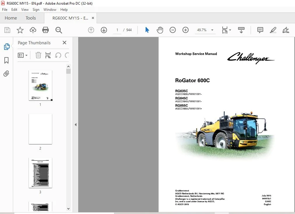
Challenger EU Applicators RG635C RG645C RG655C RoGator Workshop Service Manual
Original price was: $89.95.$32.95Current price is: $32.95.
Challenger EU Applicators RG635C RG645C RG655C RoGator Workshop Service Manual – PDF DOWNLOAD
RG635C
AGCC0635.FW001001-
RG645C
AGCC0645.FW001001-
RG655C
AGCC0655.FW001001-
Description
Challenger EU Applicators RG635C RG645C RG655C RoGator Workshop Service Manual – PDF DOWNLOAD
DESCRIPTION:
Challenger EU Applicators RG635C RG645C RG655C RoGator Workshop Service Manual – PDF DOWNLOAD
RG635C
AGCC0635.FW001001-
RG645C
AGCC0645.FW001001-
RG655C
AGCC0655.FW001001-
Foreword :
- This service manual has been prepared with the latest service information available at publication time. Read this service manual carefully before performing any service on the machine. Right-hand and left-hand, as used in manual, are determined by facing the direction machine travels when in use.
- Photos, illustrations and data used in manual were current at time of printing, but due to possible engineering and/or production changes, each machine can vary. Manufacturer reserves the right to redesign and change machine as necessary without notification.
Division and page numbers
Service manual is separated into divisions. Refer to master table of contents. Each division has an identifying part number with an revision level indicator. Each division has a table of contents and an index.
Each page is identified with division part number and revision level. Pages are in simple numeric order within each division.
Unit of measurement
Measurements are given in metric units followed by U.S. equivalent. Hardware sizes are given in millimetres for metric and inches for U.S. hardware.
Replacement parts
To receive prompt efficient service, always remember to have:
• Correct part description and part number.
• Model and serial number of machine.
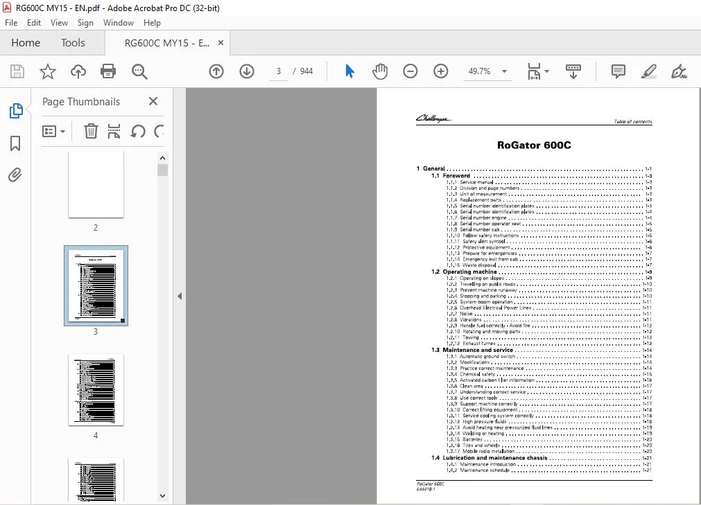
TABLE OF CONTENTS:
Challenger EU Applicators RG635C RG645C RG655C RoGator Workshop Service Manual – PDF DOWNLOAD
1 General 1-1
1 1 Foreword 1-3
1 1 1 Service manual 1-3
1 1 2 Division and page numbers 1-3
1 1 3 Unit of measurement 1-3
1 1 4 Replacement parts 1-3
1 1 5 Serial number identification plates 1-3
1 1 6 Serial number identification plates 1-4
1 1 7 Serial number engine 1-4
1 1 8 Serial number operator seat 1-5
1 1 9 Serial number cab 1-5
1 1 10 Follow safety instructions 1-5
1 1 1 1 Safety alert symbol 1-6
1 1 1 2 Protective equipment 1-6
1 1 1 3 Prepare for emergencies 1-7
1 1 1 4 Emergency exit from cab 1-7
1 1 1 5 Waste disposal 1-7
1 2 Operating machine 1-9
1 2 1 Operating on slopes 1-9
1 2 2 Travelling on public roads 1-10
1 2 3 Prevent machine runaway 1-10
1 2 4 Stopping and parking 1-10
1 2 5 System boom operation 1-1 1
1 2 6 Overhead Electrical Power Lines 1-1 1
1 2 7 Noise 1-1 1
1 2 8 Vibrations 1-1 1
1 2 9 Handle fuel correctly – Avoid fire 1-1 2
1 2 10 Rotating and moving parts 1-1 2
1 2 1 1 Towing 1-1 3
1 2 1 2 Exhaust fumes 1-1 3
1 3 Maintenance and service 1-14
1 3 1 Automatic ground switch 1-1 4
1 3 2 Modifications 1-1 4
1 3 3 Practice correct maintenance 1-1 4
1 3 4 Chemical safety 1-1 5
1 3 5 Activated carbon filter information 1-1 6
1 3 6 Clean area 1-1 7
1 3 7 Understanding correct service 1-1 7
1 3 8 Use correct tools 1-1 7
1 3 9 Support machine correctly 1-1 7
1 3 10 Correct lifting equipment 1-1 8
1 3 1 1 Service cooling system correctly 1-1 8
1 3 1 2 High pressure fluids 1-1 8
1 3 1 3 Avoid heating near pressurized fluid lines 1-1 9
1 3 1 4 Welding or heating 1-1 9
1 3 1 5 Batteries 1-20
1 3 1 6 Tires and wheels 1-20
1 3 1 7 Mobile radio installation 1-20
1 4 Lubrication and maintenance chassis 1-21
RoGator 600C
644410-1
1 4 1 Maintenance introduction 1-2 1
1 4 2 Maintenance schedule 1-2 1
Table of contents
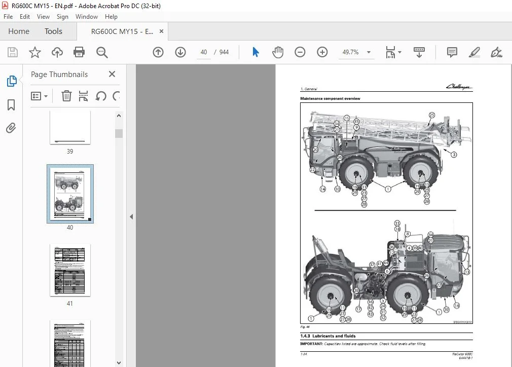
1 4 3 Lubricants and fluids 1-24
1 4 4 Recommended products 1-25
1 5 Lubrication and maintenance spray system 1-26
1 5 1 Maintenance introduction 1-26
1 5 2 Maintenance schedule 1-26
1 5 3 Lubricants and fluids 1-27
1 5 4 General spray boom maintenance 1-2 8
1 6 Jack up the machine 1-29
1 6 1 Lower the machine 1-30
1 6 2 Place jacks 1-3 1
1 6 3 Jack up procedure 1-3 1
1 7 Tire load and inflation table 1-34
1 7 1 Tire inflation table 1-34
1 7 2 320 / 10 5 R4 6 166D TL AG RI FLEX 354 1-35
1 7 3 3 8 0 / 9 0 R5 4 1 7 10 TL AGRIFLEX 350 1-36
1 7 4 3 8 0 / 9 0 R4 6 1 7 3D TL SPRAYBIB VF 1-37
1 7 5 4 8 0 / 8 0 R50 1 66D TL AGRIFLEX 35 4 1-3 8
1 7 6 5 20 / 85 R4 6 173A8 TL AGR IF LEX 385 1-39
1 7 7 620 / 70 R4 2 1 60 D T L OMNIBIB 1-40
1 7 8 620 / 75 R 34 1 70 A 8 / 1 70 B TL MEGAXBIB 1-4 1
1 7 9 7 10 / 75 R 34 1 7 8 A 8 / 1 7 8 B TL MEGAXBIB 1-4 3
1 8 Dimensions 1-45
1 9 Machine stability 1-46
1 10 Steering radius 4 wheel and 2 wheel steer 1-47
1 11 Component location 1-48
1 1 1 1 Chassis 1-4 8
1 1 1 2 Component location system 1-5 1
1 12 Service panel location 1-53
1 1 2 1 Main fuse panel 1-5 3
1 1 2 2 Automatic fuses and relays 1-5 4
1 13 Tightening specifications 1-55
1 1 3 1 Constant torque hose clamp 1-55
1 1 3 2 Metric fasteners 1-55
1 1 3 3 Inch fasteners 1-5 7
1 1 3 4 Torque values 1-5 8
1 1 3 5 Conversion table 1-5 9
2 Engine, fuel and exhaust system 2-1
2 1 Introduction 2-3
2 1 1 Specifications and standards 2-3
2 1 2 Fuel quality 2-3
2 1 3 Coolant quality 2-3
2 1 4 Oil quality 2-3
2 1 5 Engine oil type 2-4
2 1 6 Engine specification 2-4
2 1 7 Lifting and storage 2-5
2 1 8 Filling with fuel 2-5
2 2 Engine system 2-7
2 2 1 Engine components 2-7
2 2 2 Sensor location 2-8
2 2 3 Position engine sensors 2-9
2 2 4 Removing the cooling package 2-1 3
2 2 5 Taking apart the cooling package 2-14
2 2 6 Installing the cooling package 2-15
2 2 7 Removing the alternator 2-1 6
2 2 8 Installing the alternator 2-1 7
RoGator 600C
644410-1
Table of contents
2 2 9 Removing the starter 2-1 9
2 2 10 Installing the starter 2-20
2 2 1 1 Removing the engine 2-2 2
2 2 1 2 Installing the engine 2-25
2 2 1 3 Removing the airfilter 2-2 9
2 2 14 Installing the airfilter 2-3 1
2 2 15 Removing the oil filter 2-3 2
2 2 1 6 Installing the oil filter 2-3 3
2 3 Fuel system 2-35
2 3 1 Bleeding fuel system 2-35
2 3 2 Removing the fuel filters 2-35
2 3 3 Installing the fuel filters 2-3 7
2 3 4 Removing the inline fuel filter 2-3 9
2 3 5 Installing the inline fuel filter 2-40
2 3 6 Removing the fuel tank 2-4 1
2 3 7 Installing the fuel tank 2-4 1
2 4 Exhaust 2-42
2 4 1 SCR system 2-4 2
2 4 2 Components SCR 2-4 4
2 4 3 Removing the exhaust 2-4 8
2 4 4 Installing the exhaust 2-4 9
2 4 5 Removing the supply module 2-5 0
2 4 6 Installing the supply module 2-5 0
2 4 7 Removing the D EF filter 2-5 1
2 4 8 Installing the D EF filter 2-5 2
2 4 9 Removing the dosing module 2-5 4
2 4 10 Installing the D osing module 2-5 4
2 4 1 1 Trouble shooting D EF system 2-55
3 Axles 3-1
3 1 Component location 3-3
3 2 Replacing track width sensor 3-4
3 3 Wheel legs 3-5
3 3 1 Removing wheel leg 3-5
3 3 2 Installing wheel leg 3-7
3 4 Sliding axles 3-9
3 4 1 Removing sliding axle bearings 3-9
3 4 2 Installing sliding axle bearings 3-9
3 4 3 Removing sliding axles 3-1 3
3 4 4 Installing sliding axles 3-14
3 5 Replacing the Kingpin bolts 3-15
4 Frame and suspension 4-1
4 1 Frame 4-3
4 2 General information 4-4
4 2 1 Machine height sensor 4-4
4 2 2 Adaptive suspension 4-5
5 Steering system 5-1
5 1 Sensors 5-3
5 1 1 Steer angle sensors 5-3
5 1 2 AutoGuide sensor 5-4
5 1 3 Replacing sensors 5-4
5 2 Steering cylinder 5-6
6 Drive train system 6-1
RoGator 600C
644410-1
Table of contents
6 1 Drive pump system 6-3
6 1 1 General 6-3
6 1 2 Diagram 6-4
6 1 3 Bypass hydraulic drive pump 6-5
7 Brake system 7-1
7 1 Brake system 7-3
7 1 1 Introduction 7-3
7 1 2 General information 7-3
7 1 3 Brake system overview 7-4
7 1 4 Brake valve block 7-7
7 2 Service brake 7-9
7 2 1 Releasing pressure 7-9
7 2 2 Bleeding brake 7-9
7 2 3 Replacing brake discs 7-9
7 3 Parking brake emergency release 7-20
7 3 1 Park brake switch 7-20
7 3 2 Removing gear axle 7-2 1
8 Air system 8-1
8 1 Air System Operation 8-3
8 1 1 Main components 8-3
8 1 2 Air compressor 8-3
8 1 3 Air dryer 8-4
8 1 4 Air tank 8-4
8 1 5 Air governor 8-4
8 1 6 Trailer brake 8-5
8 2 Air tank 8-6
8 2 1 Removing air tank 8-6
8 2 2 Installing air tank 8-6
8 3 Air compressor 8-8
8 3 1 Removing air compressor 8-8
8 3 2 Installing air compressor 8-8
8 4 Air dryer 8-1 0
8 4 1 Removing air dryer 8-10
8 4 2 Installing air dryer 8-10
8 4 3 Air dryer components 8-10
9 Hydraulic system 9 -1
9 1 Introduction 9 -3
9 1 1 High pressure fluids 9-3
9 1 2 Avoid heating near pressurized fluid lines 9-4
9 1 3 Theory of operation 9-4
9 1 4 Component location and function 9-5
9 1 5 Hydraulic system 9-6
9 1 6 Pressure measurement 9-9
9 1 7 Lubricants and fluids 9-1 1
9 1 8 Replacing a cartridge 9-1 1
9 2 Control valves 9 -1 2
9 2 1 Removal 9-1 2
9 2 2 Installation 9-1 2
9 2 3 Inspection 9-1 3
9 2 4 Assembly 9-1 3
9 3 Auxiliary valve 9 -1 5
9 3 1 Disassembly 9-1 5
9 3 2 Inspection 9-1 6
RoGator 600C
644410-1
Table of contents
9 3 3 Assembly 9-1 6
9 4 Cylinders 9 -18
9 4 1 Seal kit replacement 9-1 8
9 4 2 Inspection 9-1 9
9 4 3 Assembly 9-1 9
9 5 Hydraulic load sensing system 9 -21
9 5 1 General 9-2 1
9 5 2 System overview 9-2 1
9 5 3 Overview valve block 9-24
9 5 4 Sliding axles 9-30
9 5 5 Spray pack hydraulics 9-3 1
9 6 Hydraulic centrifugal pump system 9 -39
9 6 1 General 9-39
9 6 2 System overview 9-39
10 Electrical system 10 -1
10 1 General information 10 -7
10 1 1 Introduction 10-7
10 1 2 Basic troubleshooting procedures 10-7
10 1 3 Tools 10-7
10 1 4 General testing procedures 10-8
10 1 5 Wire colors 10-1 1
10 2 Electrical system 10 -12
10 2 1 D escription 10-1 2
10 2 2 Requirements 10-1 2
10 2 3 D efinition 10-1 2
10 2 4 Component location 10-1 3
10 2 5 CAN bus overview 10-14
10 3 Service panel locations 10 -35
10 3 1 Fuse panel 10-35
10 3 2 Main fuse panel 10-35
10 3 3 Fuse panel descriptions 10-35
10 3 4 Fuse block CP0 3 10-36
10 3 5 Fuse block CP0 4 10-3 7
10 3 6 Fuse block CP0 5 10-3 8
10 3 7 Relay block CP0 5 10-39
10 3 8 Fuse block CP0 6 10-40
10 3 9 Relay block CP0 6 10-4 1
10 3 10 Automatic fuses and relays 10-4 1
10 4 Measuring values 10 -4 3
10 4 1 Chassis Signals (CCH) 10-4 3
10 4 2 System signals (CCS) 10-4 7
10 5 Pinouts 10 -51
10 5 1 4WS Suspension controller 10 -5 1
10 5 2 ASC-10 controller 1 0-5 2
10 6 Error codes on controller display 10 -55
10 7 Error codes Engine Module 10 -6 1
10 7 1 Error code 0 1 0 0 1 10-6 1
10 7 2 Error code 0 1 0 0 6 10-62
10 7 3 Error code 0 1 0 0 7 10-62
10 8 Error codes Chassis ECU 10 -6 4
RoGator 600C
644410-1
10 8 1 Error code 0 0 1 0 1 10-64
10 8 2 Error code 0 1 1 0 2 10-64
10 8 3 Error code 0 1 1 0 3 10-65
10 8 4 Error code 0 1 1 0 4 10-66
10 8 5 Error code 0 1 1 0 5 10-67
Table of contents
10 8 6 Error code 0 1 2 0 8 10-69
10 8 7 Error code 0 4 0 0 1 10-7 1
10 8 8 Error code 0 4 0 0 2 10-7 2
10 8 9 Error code 0 4 0 0 3 10-7 3
10 8 10 Error code 0 4 0 0 4 10-74
10 8 1 1 Error code 0 4 0 0 5 10-76
10 8 1 2 Error code 0 4 0 0 6 10-77
10 8 1 3 Error code 0 4 0 0 7 10-7 9
10 8 14 Error code 0 4 0 0 8 10-80
10 8 15 Error code 0 4 0 0 9 10-8 2
10 8 1 6 Error code 0 4 0 10 10-84
10 8 1 7 Error code 0 4 0 1 1 10-85
10 8 1 8 Error code 0 4 0 1 2 10-8 7
10 8 1 9 Error code 0 4 0 1 3 10-8 8
10 8 20 Error code 0 4 0 14 10-90
10 8 2 1 Error code 0 4 0 15 10-9 1
10 8 2 2 Error code 0 4 0 1 6 10-9 3
10 8 2 3 Error code 0 4 0 1 7 10-95
10 8 24 Error code 0 4 0 1 9 10-9 7
10 8 25 Error code 0 4 0 20 10-9 9
10 8 2 6 Error code 0 4 0 2 1 10-10 1
10 8 27 Error code 0 4 0 2 2 10-10 3
10 8 2 8 Error code 0 4 0 2 3 10-10 5
10 8 2 9 Error code 0 4 0 24 10-10 7
10 8 30 Error code 0 4 0 25 10-10 8
10 8 3 1 Error code 0 4 0 26 10-1 1 1
10 8 3 2 Error code 0 4 0 27 10-1 1 2
10 8 33 Error code 0 4 0 2 8 10-1 15
10 8 34 Error code 0 4 0 2 9 10-1 1 7
10 8 35 Error code 0 4 0 30 10-1 1 9
10 8 36 Error code 0 4 0 3 1 10-1 2 1
10 8 37 Error code 0 4 0 34 10-1 2 3
10 8 3 8 Error code 0 4 0 35 10-1 25
10 8 3 9 Error code 0 4 0 36 10-1 2 6
10 8 40 Error code 0 4 0 37 10-1 2 8
10 8 4 1 Error code 0 4 0 3 8 10-1 2 9
10 8 4 2 Error code 0 4 0 39 10-1 3 1
10 8 4 3 Error code 0 4 0 40 10-1 3 3
10 8 44 Error code 0 4 0 4 1 10-1 3 3
10 8 45 Error code 0 4 0 4 2 10-1 36
10 8 4 6 Error code 0 4 0 4 3 10-1 3 8
10 8 4 7 Error code 0 4 0 4 4 10-14 1
10 8 4 8 Error code 0 4 0 4 8 10-14 3
10 8 4 9 Error code 0 4 0 4 9 10-144
10 8 5 0 Error code 0 4 0 5 0 10-145
10 8 5 1 Error code 0 4 0 5 1 10-145
10 8 5 2 Error code 0 4 0 5 2 10-14 6
10 8 5 3 Error code 0 4 2 45 10-14 8
10 8 5 4 Error code 0 4 2 4 6 10-14 8
10 8 55 Error code 0 4 2 4 7 10-14 9
10 8 5 6 Error code 0 4 2 5 3 10-15 0
10 8 5 7 Error code 1 8 0 0 3 10-15 1
10 8 5 8 Error code 1 8 0 0 4 10-15 1
10 8 5 9 Error code 1 8 0 37 10-15 2
10 8 60 Error code 1 8 0 3 8 10-15 4
10 8 6 1 Error code 1 8 0 39 10-15 6
10 8 62 Error code 1 8 2 4 4 10-15 7
10 8 63 Error code 27 1 0 1 10-15 8
RoGator 600C
644410-1
Table of contents
10 8 64 Error code 27 1 0 2 10-15 9
10 8 65 Error code 27 1 0 4 10-160
10 8 66 Error code 27 1 05 10-162
10 8 67 Error code 27 1 0 6 10-163
10 8 68 Error code 27 1 0 7 10-166
10 8 69 Error code 27 1 0 8 10-167
10 8 70 Error code 2 7 1 0 9 10-1 69
10 8 7 1 Error code 2 7 1 10 10-170
10 8 7 2 Error code 2 7 1 1 1 10-1 7 2
10 8 7 3 Error code 2 7 1 1 2 10-174
10 8 74 Error code 2 7 1 1 3 10-175
10 8 75 Error code 2 7 1 14 10-1 77
10 8 76 Error code 2 7 1 15 10-1 7 8
10 8 77 Error code 2 7 1 1 6 10-1 8 0
10 8 7 8 Error code 2 7 1 1 8 10-1 8 3
10 8 7 9 Error code 30 0 0 7 10-1 8 4
10 8 8 0 Error code 30 0 0 8 10-1 8 7
10 8 8 1 Error code 30 1 0 1 10-1 8 7
10 8 8 2 Error code 30 1 0 2 10-1 8 9
10 8 8 3 Error code 30 1 0 3 10-1 9 1
10 8 8 4 Error code 30 1 0 4 10-1 9 2
10 8 8 5 Error code 30 1 0 5 10-1 9 4
10 8 8 6 Error code 30 1 0 6 10-1 9 6
10 8 8 7 Error code 5 0 1 4 1 10-1 9 8
10 8 8 8 Error code 5 0 1 4 2 10-20 0
10 8 8 9 Error code 5 3 1 0 1 10-20 1
10 8 90 Error code 5 3 1 0 2 10-20 2
10 8 9 1 Error code 5 3 1 0 3 10-20 3
10 8 9 2 Error code 5 3 1 0 4 10-20 4
10 8 9 3 Error code 5 3 1 0 5 10-20 6
10 8 9 4 Error code 5 3 1 0 6 10-20 8
10 8 95 Error code 5 3 1 0 7 10-2 10
10 8 9 6 Error code 5 4 1 0 1 10-2 10
10 9 Error codes Sprayer ECU 1 0 -21 2
RoGator 600C
644410-1
10 9 1 Error code 2 9 1 0 1 10-2 1 2
10 9 2 Error code 2 9 1 0 2 10-2 1 2
10 9 3 Error code 2 9 1 0 3 10-2 1 3
10 9 4 Error code 2 9 1 0 4 10-2 15
10 9 5 Error code 2 9 1 0 5 10-2 1 6
10 9 6 Error code 2 9 1 0 6 10-2 1 9
10 9 7 Error code 2 9 1 0 7 10-220
10 9 8 Error code 2 9 1 0 8 10-2 23
10 9 9 Error code 2 9 1 0 9 10-224
10 9 10 Error code 5 0 1 0 1 10-2 2 7
10 9 1 1 Error code 5 0 1 0 2 10-2 2 7
10 9 1 2 Error code 5 0 1 0 3 10-2 2 8
10 9 1 3 Error code 5 0 1 0 4 10-2 2 9
10 9 14 Error code 5 0 1 0 5 10-2 3 1
10 9 15 Error code 5 0 1 0 6 10-2 3 2
10 9 1 6 Error code 5 0 1 0 7 10-234
10 9 1 7 Error code 5 0 1 0 8 10-235
10 9 1 8 Error code 5 0 1 0 9 10-2 37
10 9 1 9 Error code 5 0 1 10 10-2 3 8
10 9 20 Error code 5 0 1 1 1 10-240
10 9 2 1 Error code 5 0 1 1 2 10-24 1
10 9 2 2 Error code 5 0 1 1 3 10-24 3
10 9 2 3 Error code 5 0 1 14 10-24 4
10 9 24 Error code 5 0 1 15 10-24 6
Table of contents
10 9 25 Error code 5 0 1 1 6 10-24 7
10 9 26 Error code 50 1 17 10-24 9
10 9 27 Error code 50 1 1 8 10-250
10 9 2 8 Error code 50 1 1 9 10-25 2
10 9 29 Error code 50 1 20 10-25 3
10 9 30 Error code 5 0 1 2 1 10-255
10 9 3 1 Error code 50 1 22 10-25 6
10 9 32 Error code 50 1 23 10-25 8
10 9 33 Error code 50 1 24 10-25 9
10 9 34 Error code 5 0 1 25 10-2 6 1
10 9 35 Error code 50 1 26 10-262
10 9 36 Error code 50 1 27 10-264
10 9 37 Error code 50 1 2 8 10-265
10 9 38 Error code 50 1 29 10-267
10 9 39 Error code 50 1 30 10-268
10 9 40 Error code 50 1 3 1 10-270
10 9 4 1 Error code 5 0 1 3 2 10-2 7 1
10 9 4 2 Error code 50 1 33 10-273
10 9 4 3 Error code 5 0 1 34 10-274
10 9 44 Error code 50 1 35 10-276
10 9 45 Error code 50 1 36 10-277
10 9 4 6 Error code 50 1 37 10-279
10 9 4 7 Error code 5 0 1 3 8 10-2 8 0
10 9 4 8 Error code 50 1 39 10-2 8 2
10 9 4 9 Error code 50 1 40 10-2 8 3
10 9 5 0 Error code 5 0 1 4 3 10-2 8 5
10 9 5 1 Error code 5 0 1 4 4 10-2 8 7
10 9 5 2 Error code 5 0 1 45 10-2 8 9
10 9 5 3 Error code 5 0 1 4 6 10-2 9 0
10 9 5 4 Error code 5 0 1 4 7 10-2 9 1
10 9 55 Error code 5 0 1 4 8 10-2 9 3
10 9 5 6 Error code 5 0 1 4 9 10-2 9 7
10 9 5 7 Error code 5 1 1 0 1 10-2 9 8
10 9 5 8 Error code 5 1 1 0 2 10-2 9 9
10 9 5 9 Error code 5 1 1 0 3 10-2 9 9
10 9 60 Error code 5 1 1 0 4 10-30 2
10 9 6 1 Error code 5 1 1 0 5 10-30 3
10 9 62 Error code 5 1 1 0 6 10-30 5
10 1 0 Error codes Joystick 1 0 -30 8
10 10 1 Error code 15 0 0 1 10-30 8
10 10 2 Error code 15 0 0 2 10-30 9
10 10 3 Error code 15 0 0 3 10-3 10
10 10 4 Error code 15 0 0 4 10-3 10
10 10 5 Error code 15 0 0 5 10-3 1 1
10 10 6 Error code 15 1 0 6 10-3 1 2
10 10 7 Error code 15 1 0 7 10-3 1 3
10 10 8 Error code 15 1 0 8 10-3 14
10 10 9 Error code 15 1 0 9 10-3 15
10 10 10 Error code 15 1 10 10-3 1 6
10 10 1 1 Error code 15 1 1 1 10-3 1 7
10 10 1 2 Error code 15 1 1 2 10-3 1 8
10 10 1 3 Error code 15 1 1 3 10-3 1 9
10 10 14 Error code 15 1 14 10-320
10 10 15 Error code 15 1 15 10-321
10 10 16 Error code 15 1 16 10-322
10 10 17 Error code 15 1 17 10-323
10 10 1 8 Error code 15 1 1 8 10-324
10 10 1 9 Error code 15 1 1 9 10-3 25
RoGator 600C
644410-1
Table of contents
10 10 20 Error code 15 1 20 10-3 2 6
10 10 2 1 Error code 15 1 2 1 10-3 2 7
10 11 Error codes Suspension 1 0 -329
10 1 1 1 Error code 1 8 0 0 1 10-3 2 9
10 1 1 2 Error code 1 8 0 0 2 10-330
10 1 1 3 Error code 1 8 0 0 5 10-33 1
10 1 1 4 Error code 1 8 0 0 6 10-33 3
10 1 1 5 Error code 1 8 0 0 7 10-336
10 1 1 6 Error code 1 8 0 0 9 10-33 8
10 1 1 7 Error code 1 8 0 1 1 10-340
10 1 1 8 Error code 1 8 0 1 2 10-34 2
10 1 1 9 Error code 1 8 0 1 3 10-345
10 1 1 10 Error code 1 8 0 14 10-34 7
10 1 1 1 1 Error code 1 8 0 15 10-35 0
10 1 1 1 2 Error code 1 8 0 1 7 10-35 2
10 1 1 1 3 Error code 1 8 0 1 9 10-35 4
10 1 1 14 Error code 1 8 0 2 1 10-35 6
10 1 1 15 Error code 1 8 0 2 3 10-35 8
10 1 1 1 6 Error code 1 8 0 25 10-360
10 1 1 1 7 Error code 1 8 0 27 10-362
10 1 1 1 8 Error code 1 8 0 2 9 10-365
10 1 1 1 9 Error code 1 8 0 3 1 10-367
10 1 1 20 Error code 1 8 0 33 10-369
10 1 1 2 1 Error code 1 8 0 40 10-37 1
10 1 1 2 2 Error code 1 8 0 4 1 10-372
10 1 1 2 3 Error code 1 8 0 4 3 10-37 3
10 1 1 24 Error code 1 8 0 45 10-37 3
10 1 1 25 Error code 1 8 0 4 6 10-376
10 1 1 2 6 Error code 1 8 0 4 7 10-37 9
10 1 1 2 7 Error code 1 8 0 4 8 10-3 8 1
10 12 Error codes Lighting 1 0-385
10 1 2 1 Error code 1 9 1 0 1 10-3 8 5
10 13 Error codes Optiflow 1 0 -387
10 1 3 1 Error code 2 6 1 0 1 10-3 8 7
11 Cab 1 1 -1
11 1 Cab 1 1 -3
1 1 1 1 Cab removal and installation 1 1-3
1 1 1 2 Removing the cab 1 1-4
1 1 1 3 Installing the cab 1 1-6
11 2 Adjusting the headlights 1 1-1 0
11 3 Cab filtration 1 1 -1 1
1 1 3 1 General Information 1 1-1 1
1 1 3 2 Removing the cab air filter 1 1-1 1
1 1 3 3 Installing the cab air filter 1 1-1 2
11 4 Recirculation filter 1 1 -1 4
1 1 4 1 General Information recirculation filter 1 1-14
1 1 4 2 Removing the recirculation filter 1 1-14
1 1 4 3 Installing the recirculation filter 1 1-15
11 5 Operator’s seat 1 1 -1 6
RoGator 600C
644410-1
1 1 5 1 Seat adjustments 1 1-16
1 1 5 2 D isassemble the seat 1 1-17
1 1 5 3 D isassemble the seat suspension 1 1-1 8
1 1 5 4 Inspection of seat suspension components 1 1-20
1 1 5 5 Assembly of seat suspension 1 1-2 1
1 1 5 6 D isassembly of seat adjustment rails-lateral isolator 1 1-2 2
Table of con tents
1 1 5 7 Inspection of seat adjustment rails/lateral isolator components 1 1-2 2
1 1 5 8 Reassembly of seat adjustment rails/lateral isolator 1 1-23
1 1 5 9 D isassembly of seat back and bottom cushion 1 1-2 3
1 1 5 10 Inspection of seat back and bottom cushion components 1 1-24
1 1 5 1 1 Reassembly of seat back and bottom cushion 1 1-25
1 1 5 1 2 Reassembly of three seat components 1 1-25
1 1 5 1 2 1 Installation 1 1-25
1 1 5 1 3 Seat belts and instructor’ s seat 1 1-2 6
1 1 6 Floormat 1 1 -27
1 1 6 1 Removing the f loormat 1 1-2 7
1 1 6 2 Inspection of the f loormat 1 1-27
1 1 6 3 Installing the floormat 1 1-2 7
1 1 7 Bottom panel (s) 1 1 -28
1 1 7 1 Removing the bottom panel 1 1-2 8
1 1 7 2 Inspection of the bottom panels 1 1-2 8
1 1 7 3 Installing the bottom panel 1 1-2 8
1 1 8 Steeri n g pedestal 1 1 -29
1 1 8 1 Removing the pedestal 1 1-2 9
1 1 8 2 Installing the pedestal 1 1-3 2
1 1 9 Operator console 1 1 -37
1 1 9 1 Removing the operator console 1 1-37
1 1 9 2 Installing the operator console 1 1-37
1 1 1 0 Door 1 1 -38
1 1 10 1 Removing the door 1 1-38
1 1 10 2 Installing the door 1 1-3 8
1 1 10 3 Setting door striker location 1 1-39
1 1 10 3 1 Verify cab pressurization 1 1-39
1 1 10 4 Removing the door handle 1 1-39
1 1 10 5 Installing the door handle 1 1-40
1 2 Air co nditi o n i n g and heating system 1 2-1
1 2 1 General i nformation 1 2-5
1 2 1 1 System operation 1 2-5
1 2 1 2 Theory of operation 1 2-6
1 2 1 3 Basics of refrigeration 1 2-6
1 2 2 Heati ng ventilation and a i r conditio n i n g (HVAC) system 1 2-7
1 2 2 1 Components 1 2-7
1 2 2 2 M anual and electronic HVAC controls 1 2-7
1 2 2 3 Cab pressuriz ation 1 2-7
1 2 2 4 Removal of moisture f rom cab air f low 1 2-7
1 2 2 5 Cab air flow circulation 1 2-7
1 2 2 6 Cab air flow heating 1 2-7
1 2 2 7 Cab air flow cooling 1 2-8
1 2 3 Contro l panel 1 2-9
1 2 3 1 Automatic Temperature Control (ATC) 1 2-9
1 2 3 2 ATC features 1 2-9
1 2 3 3 Automatic temperature controls 1 2-9
1 2 3 4 M aximum cooling or heating 1 2-1 1
1 2 3 5 M anual temperature control system 1 2-1 1
1 2 4 Control module 1 2-1 3
1 2 4 1 M odule in/output signals 1 2-1 3
1 2 4 2 Initializ ation (start-up) 1 2-1 3
1 2 4 3 Compressor/Clutch 1 2-14
1 2 5 Air conditi o n i n g system 1 2-1 5
1 2 5 1 Schematic system 1 2-15
1 2 5 2 Refrigerant compressor 1 2-1 6
RoGator 600C
644410-1
Table of contents
1 2 5 3 Refrigerant condenser 1 2-1 6
1 2 5 4 Orifice tube 1 2-1 7
1 2 5 5 Evaporator coil 1 2-1 7
1 2 5 6 Refrigerant pressure system 1 2-1 8
1 2 5 7 Sunlight sensor 1 2-1 9
1 2 5 8 Temperature sensors 1 2-1 9
12 6 Refrigerant compressor 12-21
1 2 6 1 Sensors for refrigerant system 1 2-2 1
1 2 6 2 Compressor clutch 1 2-2 1
1 2 6 3 Suction (Suction side) 1 2-22
1 2 6 4 Pumping 1 2-22
1 2 6 5 Compression (discharge side) 1 2-22
1 2 6 6 Compressor operation 1 2-22
12 7 Refrigerant relief valve 12-23
12 8 Refrigerant condenser 12-24
12 9 Sensor (temperature) 12-25
1 2 9 1 Cab temperature 1 2-25
1 2 9 2 Ambient temperature 1 2-25
1 2 9 3 Ventilation duct temperature 1 2-25
1 2 9 4 Evaporator coil probe 1 2-25
12 10 Evaporator coil 12-26
12 11 Electrical schematic 12-27
1 2 1 1 1 Standard box 1 2-2 7
1 2 1 1 2 D eluxe box 1 2-2 8
1 2 1 1 3 Control panel 1 2-30
12 12 Refrigerant accumulator 12-32
12 13 Heater system overview 12-33
12 14 Actuator motor (water valve) 12-35
1 2 14 1 Schematic for testing the water valve 1 2-35
12 15 Air flow 12-36
1 2 15 1 Air flow components 1 2-36
1 2 15 2 Blower fan 1 2-36
1 2 15 3 Air flow intake 1 2-36
1 2 15 4 Fresh air 1 2-37
1 2 15 5 Recirculation 1 2-37
1 2 15 6 Air flow cab 1 2-3 8
12 16 Motor (air conditioning blower) 12-39
1 2 1 6 1 Automatic temperature control (fan) 1 2-39
1 2 1 6 2 Manual fan control 1 2-39
12 17 Speed control 12-4 0
1 2 1 7 1 Automatic fan speed control 1 2-40
1 2 1 7 2 Manual mode fan speed control 1 2-40
1 2 1 7 3 Concept 1 2-40
12 18 Actuator motor (damper assembly) 12-4 1
12 19 Lubricants 12-4 2
RoGator 600C
644410-1
1 2 1 9 1 Compressors 1 2-4 2
1 2 1 9 2 Clutch 1 2-4 2
1 2 1 9 3 Condensers 1 2-4 3
1 2 1 9 4 Receiver-dryer 1 2-4 3
1 2 1 9 5 Air conditioner blower/f an 1 2-4 4
1 2 1 9 6 Air conditioner system ducts 1 2-4 4
1 2 1 9 7 Expansion valve 1 2-4 4
1 2 1 9 8 Temperature sensors 1 2-45
1 2 1 9 9 Heater system operation 1 2-45
1 2 1 9 10 Heater components and controls 1 2-45
Table of con tents
12 20 Service tools 1 2-48
1 2 20 1 Safety and safety tools 1 2-4 8
1 2 20 2 Air conditioning system service tools 1 2-4 8
1 2 20 3 Inspection & maintenance without gauges 1 2-5 2
1 2 20 4 Performance inspection 1 2-5 4
1 2 20 5 Heater system inspection 1 2-5 5
12 21 Service procedures 1 2-57
1 2 2 1 1 Manifold gauge set installation 1 2-5 7
1 2 2 1 2 Troubleshooting by manifold gauge set readings 1 2-5 8
1 2 2 1 3 Review of frequent problem areas 1 2-6 5
12 22 Refrigerants 1 2-67
1 2 2 2 1 Description and properties of refrigerants 1 2-6 7
1 2 2 2 2 Changes in service procedures 1 2-6 7
1 2 2 2 3 Recovering and recycling refrigerant 1 2-6 7
1 2 2 2 4 Evacuating and charging air conditioning system 1 2-70
12 23 Component repair or replacement 1 2-72
1 2 2 3 1 Hoses and fittings 1 2-7 2
1 2 2 3 2 Lines 1 2-7 2
1 2 2 3 3 Expansion valves 1 2-7 2
1 2 2 3 4 Expansion tubes 1 2-7 2
1 2 2 3 5 Receiver-dryer and accumulator 1 2-7 3
1 2 2 3 6 Compressor and clutch 1 2-7 3
1 2 2 3 7 Servicing compressor 1 2-7 3
12 24 HVAC specifications 1 2-74
1 2 2 4 1 Refrigerant compressor 1 2-7 4
12 25 Troubleshooting 1 2-76
1 2 2 5 1 Troubleshooting preparation 1 2-7 6
1 2 2 5 2 General troubleshooting 1 2-7 6
1 2 2 5 3 Visual inspection 1 2-7 7
1 2 2 5 4 Troubleshooting faults with service codes (active) 1 2-7 7
1 2 2 5 5 Leak checking 1 2-8 2
1 2 2 5 6 Oil level measurement (in vehicle) 1 2-8 2
1 2 2 5 7 Troubleshooting NC control 1 2-8 6
1 2 2 5 8 HVAC control system variations 1 2-8 8
1 2 2 5 8 1 Binary and trinary switch 1 2-8 8
1 2 2 5 9 Refrigerant 1 2-90
1 2 2 5 9 1 Refrigerant recovery 1 2-90
1 2 2 5 9 2 Install manifold gauge set (refrigerant) 1 2-9 1
1 2 2 5 9 3 Evacuate refrigerant system 1 2-9 1
1 2 2 5 9 4 Flush refrigerant system 1 2-9 4
1 2 2 5 9 5 Refrigerant leakage test 1 2-9 4
1 2 2 5 9 6 Refrigerant compressor oil check 1 2-9 5
1 2 2 5 9 7 Charge refrigerant system 1 2-9 6
1 2 2 5 9 8 Complete charge of system from a refrigerant tank with a scale 1 2-9 9
1 2 2 5 9 9 Adding additional refrigerant to a system with low charge 1 2-10 1
1 2 2 5 9 10 Remove manifold gauge set (refrigerant) 1 2-10 2
1 2 2 5 10 Sunlight sensor test 1 2-10 2
1 2 2 5 1 1 Control panel test 1 2-10 3
13 Decals 1 3-1
13 1 Safety and maintenance sign location 1 3-3
14 Wheels 1 4-1
14 1 Removing the wheels 1 4-3
14 2 Adjusting the Wheel Toe-In and Toe-Out 1 4-4
RoGator 600C
644410-1
Table of contents
15 Product containment 15-1
15 1 Calibrating the product tank 15-3
16 Primary product distribution 16 -1
16 1 Plumbing 16 -3
16 2 Component location details 16 -4
16 3 Calibrating the spray system 16- 11
17 Booms 17 -1
17 1 Boom adjustment 17 -3
17 2 Replacing folding cylinder bearing 17 -7
18 Diagrams 18 -1
18 1 Electric System 18 -3
1 8 1 1 Electric System Legend 1 8-3
1 8 1 2 Electric System Schematic 1 8-7
1 8 1 3 CAN line Schematic 1 8-5 1
1 8 1 4 Harness chassis 1 8-5 2
1 8 1 5 Harness installation chassis 1 8-5 9
1 8 1 6 Harness cab roof 1 8-67
1 8 1 7 Harness installation cab roof 1 8-68
1 8 1 8 Harness engine 1 8-69
18 2 Hydraulic system 18 -7 3
1 8 2 1 Hydraulic System Legend 1 8-73
1 8 2 2 Hydraulic System Schemat ic 1 8-75
18 3 Air system 18 -8 5
1 8 3 1 Air System Schematic 1 8-8 7
18 4 Spray system 18 -8 9
1 8 4 1 Schematic spray syst em 1 8-8 9
1 8 4 2 Spraying 1 8-9 0
1 8 4 3 Schematic filling without SPA 1 8-9 2
1 8 4 4 Schematic SPA prime phase 1 1 8-9 2
1 8 4 5 Schematic SPA prime phase 2 1 8-9 3
1 8 4 6 Schematic direct fill (option) 1 8-9 3
1 8 4 7 Schematic filling clean wat er tank 1 8-9 4
1 8 4 8 Schematic recirculat ion 1 8-9 4
1 8 4 9 Schematic agitat ion 1 8-9 5
1 8 4 10 Schematic agitation+ + 1 8-9 6
1 8 4 1 1 Schematic eductor 1 8-9 7
1 8 4 1 2 Schematic transfer 1 8-9 8
1 8 4 1 3 Schematic draining product tank 1 8-9 8
1 8 4 14 Schematic ecomatic fill 1 8-9 9
19 Special Tools 19 -1
19 1 Special Tools 19- 3
20 Index l n d ex -1
RoGator 600C
FILE DETAILS:
Challenger EU Applicators RG635C RG645C RG655C RoGator Workshop Service Manual – PDF DOWNLOAD
Size: 157 MB
Format: PDF
Language: English
Brand: Challenger
Type of Machine: Applicators
Type of document: Workshop Service Manual
Model: Challenger EU RoGator 600C RG635C RG645C RG655C
Serial Number: SNAGCC0635.FW001001 –
Number of Pages: 944 pages
Date Modified: 07/2015
Part Number: 644410-1
CHALLENGER EU APPLICATORS RG635C RG645C RG655C ROGATOR WORKSHOP SERVICE MANUAL:
IMAGES PREVIEW OF THE MANUAL:


PLEASE NOTE:
- This is not a physical manual but a digital manual – meaning no physical copy will be couriered to you. The manual can be yours in the next 2 mins as once you make the payment, you will be directed to the download page IMMEDIATELY.
- This is the same manual used by the dealers inorder to diagnose your vehicle of its faults.
- Require some other service manual or have any queries: please WRITE to us at [email protected]
S.V