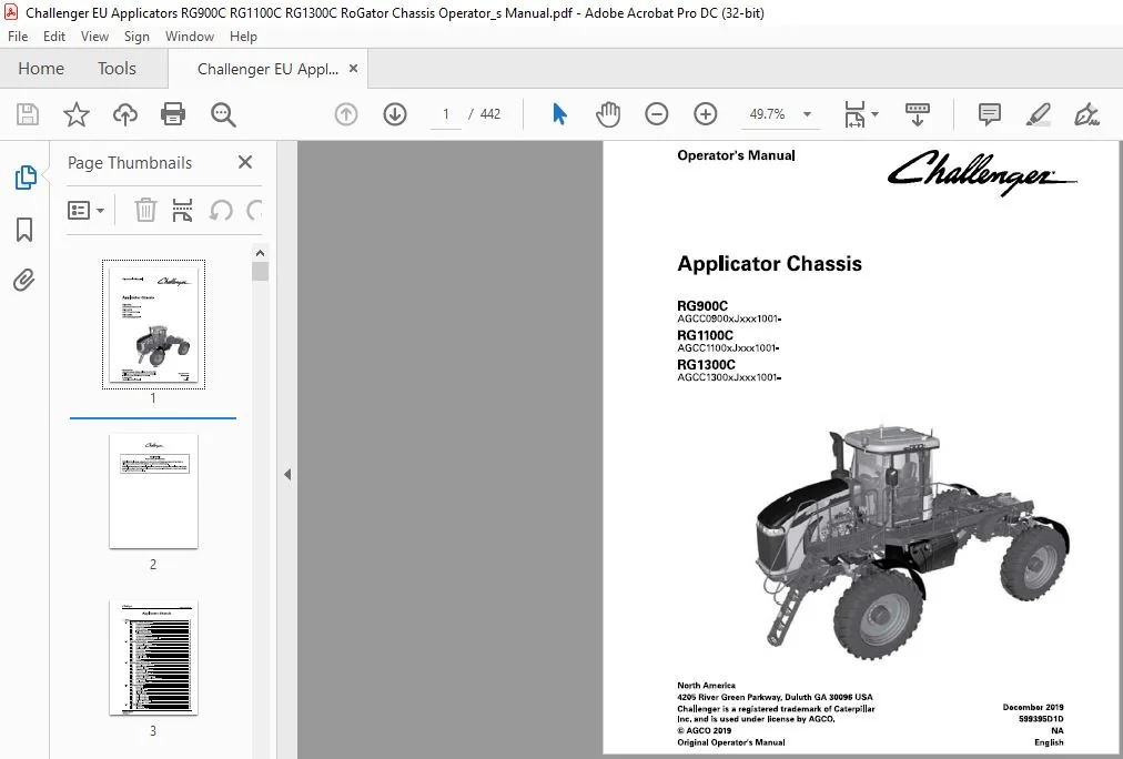

Challenger EU Applicators RG900C RG1100C RG1300C RoGator Chassis Operator’s Manual 599395D1D
Original price was: $89.95.$23.95Current price is: $23.95.
Challenger EU Applicators RG900C RG1100C RG1300C RoGator Chassis Operator’s Manual 599395D1D – PDF DOWNLOAD
RG900C
AGCC0900xJxxx1001-
RG1100C
AGCC1100xJxxx1001-
RG 1300C
AGCC1300xJxxx1001-
North
Description
Challenger EU Applicators RG900C RG1100C RG1300C RoGator Chassis Operator’s Manual 599395D1D – PDF DOWNLOAD
IMAGES PREVIEW OF THE MANUAL:


FILE DETAILS:
Challenger EU Applicators RG900C RG1100C RG1300C RoGator Chassis Operator’s Manual 599395D1D – PDF DOWNLOAD
Size: 62.6 MB
Format: PDF
Language: English
Brand: Challenger
Type of Machine: Applicators
Type of document: Operator’s Manual
Model: Challenger EU RoGator RG900C RG1100C RG1300C Applicator Chassis
Number of Pages: 442 pages
Serial Number: AGCCXX00XJXXX1001-
RG900C AGCC0900XJXXX1001-
RG1100C AGCC1100XJXXX1001-
RG1300C AGCC1300XJXXX1001-
Part Number: 599395D1D
DESCRIPTION:
Challenger EU Applicators RG900C RG1100C RG1300C RoGator Chassis Operator’s Manual 599395D1D – PDF DOWNLOAD
RG900C
AGCC0900xJxxx1001-
RG1100C
AGCC1100xJxxx1001-
RG 1300C
AGCC1300xJxxx1001-
North
Important safety information :
Most accidents that involve product operation, maintenance and repair are caused by failure to observe basic safety rules or precautions. An accident can often be avoided by recognizing potentially hazardous situations before an accident occurs. A person must be alert to potential hazards. This person must also have the necessary training, skills and tools to do these functions correctly. Incorrect operation, lubrication, maintenance, or repair of this product can be dangerous and can result in injury or death.
- Do not operate or do any lubrication, maintenance or repair on this product, until you read and understand the operation, lubrication, maintenance, and repair information. Safety precautions and warnings are provided in this manual and on the product. If these hazard warnings are not heeded, bodily injury or death can occur to you or other persons. AGCO cannot anticipate every possible circumstance that might involve a potential hazard.
- The warnings in this publication and on the product are, thus, not all-inclusive. If a tool, procedure, work method or operating technique that is not specifically recommended by AGCO is used, you must satisfy yourself that it is safe for you and others. You must make sure the product will not be damaged or made unsafe by the operation, lubrication, maintenance, or repair procedures that you choose.
- The information, specifications, and illustrations in this publication are based on the information that was available at the time that the publication was written. The specifications, torques, pressures, measurements, adjustments, illustrations, and other items can change at any time.
- These changes can affect the service that is given to the product. Obtain the complete and most current information before you start any job. AGCO dealers have the most current information available.
Prepare for operation:
Read and understand all operation instructions and precautions in this manual before you operate the machine or do the servicing. Make sure that you know and understand the positions and operations of all controls. Make sure that all controls are in neutral and that the parking brake is applied before you start the machine. Make sure that all persons are away from your area of work before you start and operate the machine.
- Examine and learn the controls in an area that is clear of persons and obstacles before you start work. Know the machine dimensions and make sure that you have sufficient space available to operate the machine.
- Do not operate the machine at high speeds in crowded areas. It is important to know and use the correct procedures when you do work around and operate the machine. Do not let children or unqualified persons operate the machine.
- Keep others, especially children, away from your area of work. Do not let others ride on the machine. Make sure that the machine is in good condition for operation. Refer to the operator manual. Make sure that the machine has the correct equipment required by local regulations.
TABLE OF CONTENTS:
Challenger EU Applicators RG900C RG1100C RG1300C RoGator Chassis Operator’s Manual 599395D1D – PDF DOWNLOAD
1 Safety 13
11 Important safety information 15
111 Prepare for operation 15
112 A word to the operator 16
113 Safety symbol 17
114 Safety messages 17
115 Information messages 17
116 Follow safety instructions 18
11 7 Prepare for emergencies 18
118 Fire prevention 19
119 Prevent static discharge when fueling 19
1110 Exit the cab in an emergency19
12 Operate the machine21
121 Prevent machine runaway22
122 Use correct lamps and markers 22
123 Operation on slopes 22
124 Travel on public roads 23
125 Stop and park 23
126 System boom operation23
127 Exhaust fumes 24
128 Noise prevention 24
129 Handle fuel correctly 24
1210 Towing25
1211 Modifications 25
13 Maintenance and service 26
131 Practice correct maintenance26
132 Chemical safety 27
133 Work in a clean area 29
134 Understand correct service 30
135 Use correct tools 30
136 Support machine correctly 31
137 High pressure fluids 31
138 Service cooling system correctly 32
139 Remove paint before welding or heating32
1310 Tires and wheels 33
1311 Mobile radio installations 33
1312 Fire prevention 33
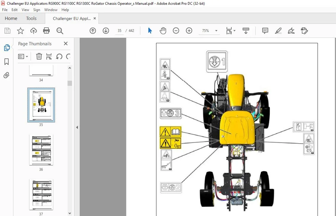
14 Cab safety signs 35
141 Read manual36
142 Break glass – exit 36
143 Sound horn 36
144 Electrical hazard 36
145 Run-over hazard 37
146 Cab filter number 2 37
147 Cab filter number 3 37
148 Cab filter number 1 37
149 Roll over – wear seat belt 38
1410 Run over – no riders 38
15 Electrical signs39
151 Radar hazard 40
152 Electrocution hazard 40
Applicator Chassis
599395010
Table of contents
153 Fuse/relay and battery sign 40
154 Battery box fuse/relay sign – 602692D1 40
155 Cab fuse/relay sign – ACW714566041
16 Chassis signs42
161 Fall off hazard 43
162 Air dump 43
163 Roll over 43
164 Pinch hazard43
165 Tie down 44
166 Lift point 44
167 Drain the air tank 44
168 Hand wash 44
169 Axle spacing left-hand 45
1610 Axle spacing right-hand45
17 Hydraulic signs 46
171 Explosion injury hazard 47
172 High pressure hazard 47
18 Engine signs 48
181 Separator filter 49
182 Fuel filter49
183 Fuel water separator head 49
184 High pressure hazard 50
185 Entanglement 50
186 Entanglement 50
187 Run over hazard51
188 Ether 51
189 Diesel exhaust fluid filter 51
1810 Fuel filter 51
1811 Burnhazard 52
2 Introduction 53
21 Introduction 55
211 Intended use55
212 Proper disposal of waste 55
213 Pre-delivery checklist 55
22 Serial number identification 56
221 Serial number definition57
23 Hydrostatic drive system 58
231 Hydrostatic drive system introduction 58
232 Drive lever 58
233 Hydraulic drive pump 59
234 Charge pump59
235 Oil cooler 60
236 Hydraulic system oil filters 60
24 Component locations62
25 Fuses and relays 64
251 Fuse/relay panel 64
252 Main fuses 71
253 Chassis harness fuses 71
254 Power distribution module 71
26 Selective catalytic reduction (SCR) System74
261 Diesel exhaust fluid (DEF) tank 74
262 Diesel exhaust fluid (DEF) storage 74
27 Emissions warranty 75
2 71 United States and Canada emission control warranty statement 75
272 California emission control warranty statement 78
Applicator Chassis
599395010
Table of contents
3 Operation 83
31 Instruments and controls 87
311 Dash panel 87
312 Operating status displays 88
313 Multiple display screens88
314 How to clear dash panel fault codes 89
315 Console keypad 91
316 Ignition switch 92
317 Multifunction lever 93
318 Set the windshield wiper delay 93
319 Tilt – telescoping lever 94
3110 Brake pedal 94
3111 Drive lever controls 95
3112 Armrest controls 95
3113 Armrest adjustment 96
3114 Chassis keypad 96
3115 Automatic heated mirrors 96
3116 Power mirror adjustment 97
3117 Interior lamps 97
3118 Radio (if equipped)98
3119 Sun Visor 98
3120 Cup holders 98
3121 Storage compartments98
3122 Power strip 99
3123 Power ports 99
3124 Cargo net 100
3125 Lamp switches 100
3126 Bluetooth microphone102
3127 Objects in the cab 102
3128 Automatic battery disconnect 102
32 Temperature control 103
321 Heater operation 103
322 Defrost or defog operation 104
323 Air conditioner operation 104
324 Automatic fan speed control104
325 Manual fan speed control 105
326 Heater water valve 105
327 Cab air temperature sensor 105
328 Pressurizer blower 105
329 Air vents 106
33 Seats 107
331 Heated and ventilated seats107
332 Basic operator seat 107
333 Deluxe operator seat 109
334 Deluxe vented operator seat111
335 Instructor seat 112
34 General inspection 114
341 Check fluids 114
342 Check for Condition and Cleanliness 114
343 Do a check of the hydraulics114
344 Check fuel system 115
345 Do a check of the cab 115
346 Check mirrors 115
34 7 Check the Hoses115
348 Check the Safety Signs115
35 Terminal117
Applicator Chassis
Terminal introduction117
Audible alarms and indicators 118
Display the chassis software information 118
Set the language 119
Set the date and time 120
Set the audio level 121
Set the screen brightness 122
Switch between day and night mode 124
Call up the USB Data screen 124
Select and transfer individual data to the USB stick 125
Select and transfer all data to the USB stick 126
Select and transfer individual data from the USB stick 128
Select and transfer all data from the USB stick 130
Clean the terminal screen 131
Calibrate the touch screen 132
Do a touch test 133
Set up the camera application – if equipped 134
View the service interval screens 135
Program the user-defined service intervals 135
Calibrate the radar 137
Calibrate the wheel speed 137
Calibrate the wheel speed and radar 138
Calibrate the steering angle sensor 139
Calibrate the steering valve140
Calibrate the lever141
Calibrate the brake pedal 142
View the diagnostic screens146
View the active errors screen 147
Set the power management values 147
Display the four wheel steer148
Set the track width presets 150
View the fuel consumption screen 151
Call up the ISOBUS Information screen 152
Set the acceleration rate 153
Select a four wheel steering mode 154
View the Auto-Guide™ map154
View the worked area settings 155
Make a wayline from the map 157
35381 AB wayline 158
35382 Contour wayline 158
35383 A+ angle wayline 159
35384 Pivot wayline 160
35385 AB coordinates wayline 160
3539 Make a boundary from the map 160
3540 Make an obstacle from the map 162
3541 Update the terminal software 164
Break-in-period 166
361 Do a check of the hydraulic system 166
362 Do a check of the wheel drive gearboxes 166
363 Coolant level 166
364 Tighten the wheel mounting hardware 166
365 Do a check of the torque rods 167
366 Do a check of the batteries167
367 Do a check of the axle shims 167
368 Change the pressure washer pump oil – if equipped 168
369 Inspect the engine belts 168
3610 Replace the fuel filter and the fuel pre-filter 168
3611 Chassis and cab modification 168
Applicator Chassis
599395010
Table of contents
37 Start the engine169
371 Cold weather start procedure 170
372 Cold weather starting procedure for hydrostatic system172
373 Cold start option 172
374 Diesel exhaust fluid (DEF) cold start 173
375 Restart a stalled engine 173
376 Engine overspeed protection 173
377 Engine anti-stall protection 173
378 Engine power limitations 173
379 Low diesel exhaust fluid (DEF) level 174
3710 Stop the engine and afterrun 175
38 Drive the machine 176
381 Drive modes 176
382 Increase the drive speed 177
383 Decrease the drive speed 178
384 Change the drive direction 179
385 Stop the machine 179
386 Traction control 180
387 Engine RPM Guidelines 180
388 Set the cruise control speeds 181
389 Set the drive handle aggressiveness 182
3810 Transmission management system (TMS) 182
3811 Set the power management values 183
3812 Weight determined speed 183
3813 Machine braking 184
3814 Backup alarm 184
39 AccuField Command 185
391 Manual configuration 185
392 General function – AccuField Command186
393 Functions and dependencies 186
394 Call up and activate AccuField Command 188
395 Joystick assignment 189
396 Record an operational sequence 190
397 Start an operational sequence192
398 Configure an operational sequence manually192
399 Step mode 194
310 GatorTrak 4 wheel steer modes 196
3101 Off mode 196
3102 2WS mode 196
3103 Auto 4WS mode 197
3104 4WS mode 197
3105 Crab mode198
3106 Automatic engagement and disengagement198
311 Track adjust199
3111 Adjustment of track width 199
3112 Adjust the manual track width 199
3113 Adjust the hydraulic track width 200
3114 Set the automatic track width 201
312 Transporting the machine 203
3121 Travel on public roads 203
3122 Air dump valve203
3123 Trailer the machine 204
3124 Load the machine204
3125 Unload the machine 206
3126 Tow the machine 207
3127 Release the park brake manually208
3128 Re-engage the park brake 210
Applicator Chassis
599395010
Table of contents
313 Camera settings 211
3131 Camera options and connections 211
3132 Position the camera image 212
3133 Change cameras212
3134 Display the camera image while reversing 213
3135 Change the camera to and from full-screen 214
3136 Adjust the brightness 215
3137 Adjust the contrast 215
3138 Adjust the color saturation 216
314 Optional pressure washer217
3141 Input water supply 217
3142 Prime the pump 217
3143 Operate the pressure washer 218
315 Optional accessories220
3151 Slingshot – if equipped220
3152 Weather station – if equipped 220
3153 Install the mini SIM card for Global System for Mobile communication (GSM) 221
316 Change the system 224
3161 Remove the liquid system 224
3162 Install the spinner system 233
3163 Install the AirMax 180 system239
3164 Remove the AirMax 180 system 242
3165 Remove the spinner system 245
3166 Install the liquid system 250
4 Engine Operation 263
41 Safety instructions 265
42 To the user 266
421 Engine type designations 266
422 Location of the engine serial number 267
423 Type plate of the electronic control unit268
43 Technical data 269
431 Principal dimensions and data 269
432 Fuel system269
433 Lubrication system 269
434 Cooling system 269
435 Selective Catalyst Reduction (SCR) system technical data 270
44 Air control system 272
441 Turbocharging 273
442 2 stage turbocharging273
443 Cooling of inlet air 273
444 Interstage charge air cooling273
445 Throttle valve 273
45 Fuel system 274
46 Engine control system 276
4 7 Lubrication system 277
4 71 Oil pressure regulating valve 279
472 Oil filter and oil cooler 279
473 Oil filter and oil cooler 280
48 Cooling system 281
481 Engine heater 281
49 Electrical system282
410 SCR system283
4101 Selective Catalyst Reduction (SCR) system overview 283
4102 Selective Catalyst Reduction (SCR) system components and their functions 284
Applicator Chassis
599395010
Table of contents
411 Operation and driving 286
412 Daily pre-start check287
413 Starting the engine 288
4131 Break in the engine 288
414 Starting the engine in cold conditions290
4141 Warming up the engine 290
415 Start the engine with an auxiliary battery 291
416 Attention during operation 292
417 Stopping the engine293
5 Maintenance 295
51 Maintenance introduction 299
511 Lubricants and fluids299
512 Fuel quality requirements 299
513 Coolant quality requirements 301
514 Oil quality 302
515 Lubricant filling reminders 302
52 Maintenance schedule 303
53 Engine maintenance information 307
531 Maintenance chart 307
532 Maintenance to be made daily or at 10 hours intervals 309
5321 Do a check for the engine oil level 309
5322 Check coolant level 309
5323 Check for leakages 310
Maintenance to be made weekly or at 100 hours interval 310
5331 Clean cooling system (from outside) 310
5332 Examining the condition of the belt 310
Maintenance to be made at 300 – 600 hours intervals 311
5341 Change engine oil 311
5342 Oil sump capacity 311
5343 Change oil filter 312
5344 Update the engine software 312
5345 How to recognize an engine with hydraulic lash adjusters 313
Change fuel filters 313
Bleed the fuel system 315
Maintenance to be made at 4000 hours intervals316
5371 Check turbocharger play and check that the intercooler cell is clean 316
Maintenance to be made once a year 316
5381 Selective Catalyst Reduction (SCR) system maintenance 316
5382 Replace the main filter and the inlet filter of the supply module 317
Maintenance to be made every two years 319
5391 Change coolant 319
5310 Additional maintenance instructions 320
53101 Before the cold season 320
53102 Tightening torques 320
53103 Coolant quality requirements 321
53104 Fuel quality requirements 322
54 Support the machine 326
541 Lifting and jacking points 326
542 Release the air from the air suspension 327
543 Place the jacks 328
544 Jack up the machine 329
55 Chassis maintenance 331
551 Lubricate the axles 331
552 Torque rods332
553 Do maintenance on the torque rods and hardware333
Applicator Chassis
599395010
Table of contents
554 Install the axle bolts 333
555 Anti-roll bar334
556 Do a check and tighten the inner axle weldment 334
557 Adjust a crop deflector335
56 Wheel drive gearbox336
561 Maintenance information 336
562 Do a check of the gearbox oil level 336
563 Fill the gearbox oil 337
564 Drain and replace the oil 337
565 Do a check of the wheel drive gearbox mounting hardware 338
57 Engine maintenance 339
5 71 Do a check of the engine coolant339
572 Do a check of the engine oil 339
573 Change the engine oil and filter 340
5 74 Engine belts341
5 75 Replace the main serpentine belt341
576 Replace the belt for the air conditioner compressor and water pump 343
577 Inspect and change the air filters 344
578 Clean the cooling package 346
579 Change the engine coolant 347
58 Fuel system maintenance 349
581 Check and tighten the fuel tank bolts 349
582 Fuel quality requirements 349
583 Fuel tank 351
584 Fill the fuel system 352
585 Fuel filtration system 353
586 Change the pre-filter and fuel filter 353
587 Drain the additional fuel/water separator – if equipped 355
588 Change the fuel water separator element – if equipped356
589 Bleed the fuel system 356
5810 Fuel storage 357
5811 Remove sediment and water from the fuel tanks 357
59 Selective catalytic reduction (SCR) system 358
591 Replace the supply module filter 358
592 Fill the DEF tank359
593 DEF storage and shelf life 359
510 Hydraulic system maintenance 360
5101 Hydraulic system360
5102 Drain the hydraulic tank 360
5103 Replace the hydraulic fluid 361
5104 Replace the return oil manifold filters 361
5105 Replace the charge filter 362
5106 Replace the hydraulic tank breather 362
5107 Torque the breather cover bolts363
5108 Start up after the hydraulic oil is drained 363
5109 Diagnostic port locations 364
51010 Check the charge pressure 365
511 Electrical system maintenance 367
5111 Electrical system safety 367
5112 Replace a fuse 367
5113 Do a check on the batteries367
5114 Use a booster battery 368
5115 Remove the batteries 368
5116 Install the batteries 370
512 Cab maintenance 372
5121 Do a check of the cab mount bolts 372
5122 Cab air filters373
Applicator Chassis
599395010
Table of contents
5123 Change the primary fresh air filter374
5124 Change the secondary clean air filter 375
5125 Change the recirculation air filter377
5126 Clean the cab air filter element 378
5127 Do a check of the windshield washer reservoir 378
513 Pressure washer – if equipped379
5131 Do a check of the pressure washer pump motor oil 379
5132 Change the pressure washer pump oil – if equipped 379
5133 Change the pressure washer strainer 380
5134 Winterize the pressure washer system 381
514 Air system maintenance 382
5141 Drain the air tank382
5142 Replace the desiccant cartridge 382
515 Tire maintenance 384
5151 Tire service384
5152 Rotate the tires 384
5153 Tire safety loads and pressure 385
5154 Maximum tire loads 385
5155 Example tire inflations386
5156 Determine the load per tire 388
515 7 Replace a tire on a rim389
5158 Remove the wheel 389
5159 Install the wheel 390
51510 Tighten the wheel mounting hardware391
51511 Adjust the two wheel steer toe-in391
51512 Adjust the four wheel steer toe-in393
51513 Toe-invalues 398
516 Machine storage399
5161 Store the machine 399
5162 Operate the machine after storage 399
6 Troubleshooting 401
61 Engine troubleshooting 403
611 Engine control system fault codes 403
612 Troubleshooting of the engine 403
62 Heating and cooling troubleshooting 408
63 Dash code reference410
64 Fault code reference 411
7 Specifications427
71 Chassis specifications 429
72 Machine dimensions432
8 Index 435
CHALLENGER EU APPLICATORS RG900C RG1100C RG1300C ROGATOR CHASSIS OPERATOR’S MANUAL 599395D1D:
PLEASE NOTE:
- This is the SAME exact manual used by your dealers to fix your vehicle.
- The same can be yours in the next 2-3 mins as you will be directed to the download page immediately after paying for the manual.
- Any queries / doubts regarding your purchase, please feel free to contact [email protected]
S.V